2000 NISSAN PATROL check engine
[x] Cancel search: check enginePage 681 of 1033
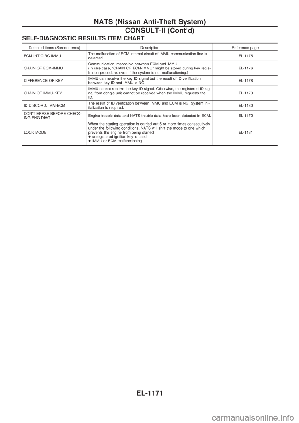
SELF-DIAGNOSTIC RESULTS ITEM CHART
Detected items (Screen terms) Description Reference page
ECM INT CIRC-IMMUThe malfunction of ECM internal circuit of IMMU communication line is
detected.EL-1175
CHAIN OF ECM-IMMUCommunication impossible between ECM and IMMU.
(In rare case, ªCHAIN OF ECM-IMMUº might be stored during key regis-
tration procedure, even if the system is not malfunctioning.)EL-1176
DIFFERENCE OF KEYIMMU can receive the key ID signal but the result of ID verification
between key ID and IMMU is NG.EL-1178
CHAIN OF IMMU-KEYIMMU cannot receive the key ID signal. Otherwise, the registered ID sig-
nal from dongle unit cannot be received when the IMMU requests the
ID.EL-1179
ID DISCORD, IMM-ECMThe result of ID verification between IMMU and ECM is NG. System ini-
tialization is required.EL-1180
DON'T ERASE BEFORE CHECK-
ING ENG DIAGEngine trouble data and NATS trouble data have been detected in ECM. EL-1172
LOCK MODEWhen the starting operation is carried out 5 or more times consecutively
under the following conditions, NATS will shift the mode to one which
prevents the engine from being started.
+unregistered ignition key is used
+IMMU or ECM malfunctioningEL-1181
NATS (Nissan Anti-Theft System)
CONSULT-II (Cont'd)
EL-1171
Page 682 of 1033
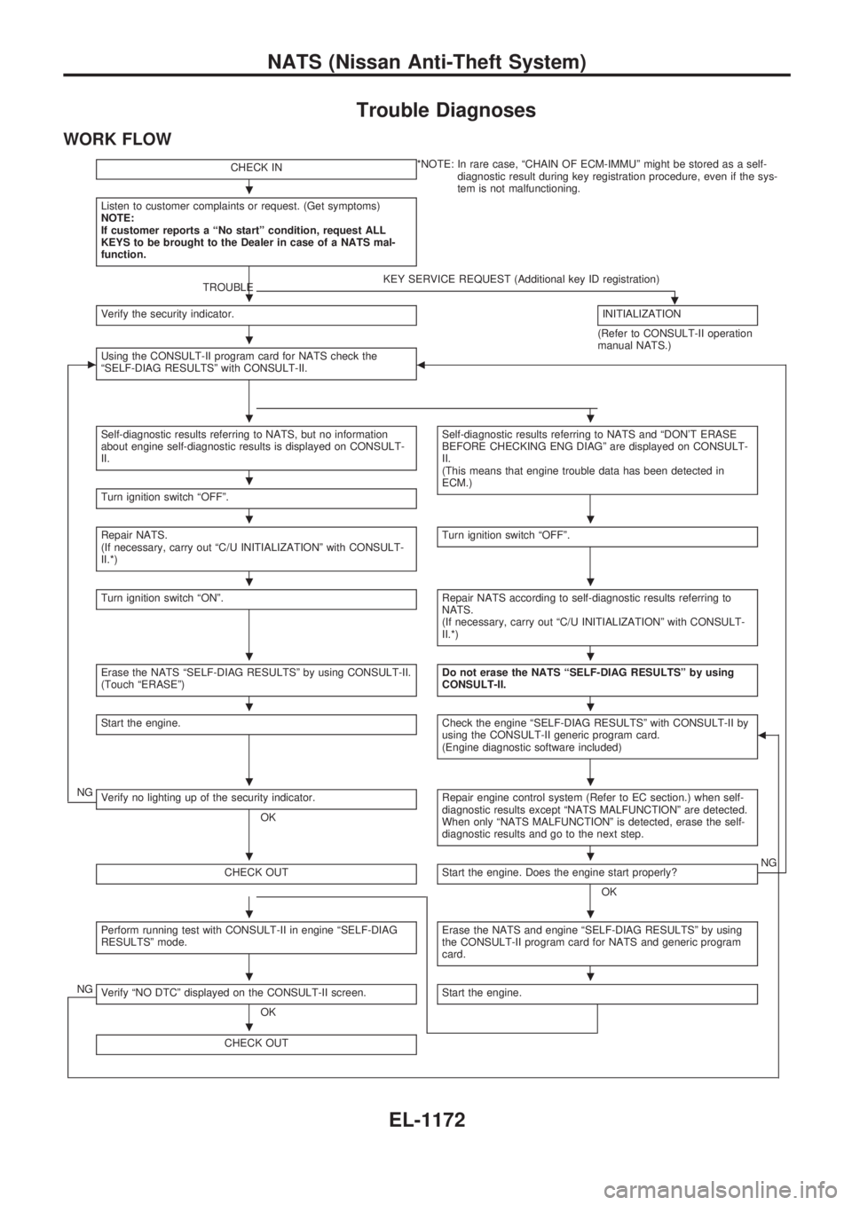
Trouble Diagnoses
WORK FLOW
CHECK IN*NOTE: In rare case, ªCHAIN OF ECM-IMMUº might be stored as a self-
diagnostic result during key registration procedure, even if the sys-
tem is not malfunctioning.
Listen to customer complaints or request. (Get symptoms)
NOTE:
If customer reports a ªNo startº condition, request ALL
KEYS to be brought to the Dealer in case of a NATS mal-
function.
TROUBLEKEY SERVICE REQUEST (Additional key ID registration).Verify the security indicator.INITIALIZATION
(Refer to CONSULT-II operation
manual NATS.)
cUsing the CONSULT-II program card for NATS check the
ªSELF-DIAG RESULTSº with CONSULT-II.b
Self-diagnostic results referring to NATS, but no information
about engine self-diagnostic results is displayed on CONSULT-
II.Self-diagnostic results referring to NATS and ªDON'T ERASE
BEFORE CHECKING ENG DIAGº are displayed on CONSULT-
II.
(This means that engine trouble data has been detected in
ECM.)
Turn ignition switch ªOFFº.
Repair NATS.
(If necessary, carry out ªC/U INITIALIZATIONº with CONSULT-
II.*)Turn ignition switch ªOFFº.
Turn ignition switch ªONº.Repair NATS according to self-diagnostic results referring to
NATS.
(If necessary, carry out ªC/U INITIALIZATIONº with CONSULT-
II.*)
Erase the NATS ªSELF-DIAG RESULTSº by using CONSULT-II.
(Touch ªERASEº)Do not erase the NATS ªSELF-DIAG RESULTSº by using
CONSULT-II.
Start the engine.Check the engine ªSELF-DIAG RESULTSº with CONSULT-II by
using the CONSULT-II generic program card.
(Engine diagnostic software included)b
NGVerify no lighting up of the security indicator.
OKRepair engine control system (Refer to EC section.) when self-
diagnostic results except ªNATS MALFUNCTIONº are detected.
When only ªNATS MALFUNCTIONº is detected, erase the self-
diagnostic results and go to the next step.
CHECK OUTStart the engine. Does the engine start properly?
OKNG
Perform running test with CONSULT-II in engine ªSELF-DIAG
RESULTSº mode.Erase the NATS and engine ªSELF-DIAG RESULTSº by using
the CONSULT-II program card for NATS and generic program
card.
NGVerify ªNO DTCº displayed on the CONSULT-II screen.
OKStart the engine.
CHECK OUT
.
.
.
..
.
..
..
..
..
..
..
..
..
.
NATS (Nissan Anti-Theft System)
EL-1172
Page 683 of 1033
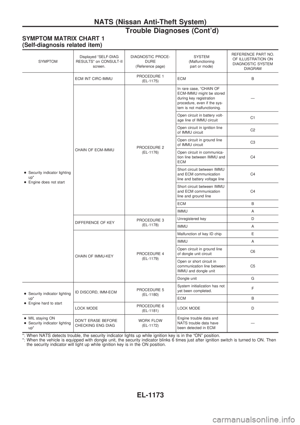
SYMPTOM MATRIX CHART 1
(Self-diagnosis related item)
SYMPTOMDisplayed ªSELF-DIAG
RESULTSº on CONSULT-II
screen.DIAGNOSTIC PROCE-
DURE
(Reference page)SYSTEM
(Malfunctioning
part or mode)REFERENCE PART NO.
OF ILLUSTRATION ON
DIAGNOSTIC SYSTEM
DIAGRAM
+Security indicator lighting
up*
+Engine does not startECM INT CIRC-IMMUPROCEDURE 1
(EL-1175)ECM B
CHAIN OF ECM-IMMUPROCEDURE 2
(EL-1176)In rare case, ªCHAIN OF
ECM-IMMU might be stored
during key registration
procedure, even if the sys-
tem is not malfunctioning.Ð
Open circuit in battery volt-
age line of IMMU circuitC1
Open circuit in ignition line
of IMMU circuitC2
Open circuit in ground line
of IMMU circuitC3
Open circuit in communica-
tion line between IMMU and
ECMC4
Short circuit between IMMU
and ECM communication
line and battery voltage lineC4
Short circuit between IMMU
and ECM communication
line and ground lineC4
ECM B
IMMU A
DIFFERENCE OF KEYPROCEDURE 3
(EL-1178)Unregistered key D
IMMU A
CHAIN OF IMMU-KEYPROCEDURE 4
(EL-1179)Malfunction of key ID chip E
IMMU A
Open circuit in ground line
of dongle unit circuitC6
Open or short circuit in
communication line between
IMMU and dongle unitC5
Dongle unit G
+Security indicator lighting
up*
+Engine hard to startID DISCORD, IMM-ECMPROCEDURE 5
(EL-1180)System initialization has not
yet been completed.F
ECM B
LOCK MODEPROCEDURE 6
(EL-1181)LOCK MODE D
+MIL staying ON
+Security indicator lighting
up*DON'T ERASE BEFORE
CHECKING ENG DIAGWORK FLOW
(EL-1172)Engine trouble data and
NATS trouble data have
been detected in ECMÐ
*: When NATS detects trouble, the security indicator lights up while ignition key is in the ªONº position.
*: When the vehicle is equipped with dongle unit, the security indicator blinks 6 times just after ignition switch is turned to ON. Then
the security indicator will light up while ignition key is in the ON position.
NATS (Nissan Anti-Theft System)
Trouble Diagnoses (Cont'd)
EL-1173
Page 689 of 1033
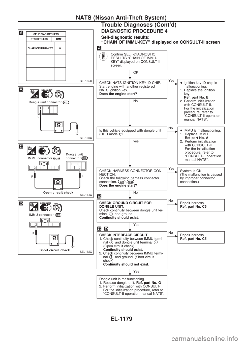
DIAGNOSTIC PROCEDURE 4
Self-diagnostic results:
ªCHAIN OF IMMU-KEYº displayed on CONSULT-II screen
Confirm SELF-DIAGNOSTIC
RESULTS ªCHAIN OF IMMU-
KEYº displayed on CONSULT-II
screen.
OK
CHECK NATS IGNITION KEY ID CHIP.
Start engine with another registered
NATS ignition key.
Does the engine start?
No
cYes
+Ignition key ID chip is
malfunctioning.
1. Replace the ignition
key.
Ref. part No. E
2. Perform initialization
with CONSULT-II.
For the initialization
procedure, refer to
ªCONSULT-II operation
manual NATSº.
Is this vehicle equipped with dongle unit
(RHD models)?
yes
cNo
+IMMU is malfunctioning.
1. Replace IMMU.
Ref part No. A
2. Perform initialization
with CONSULT-II.
For the initialization
procedure, refer to
ªCONSULT-II operation
manual NATSº.
CHECK HARNESS CONNECTOR CON-
NECTION.
Check the following harness connector
connection.
M29,M121Does the engine start?
No
cYes
System is OK.
(The malfunction is caused
by improper connector
connection.)
CHECK GROUND CIRCUIT FOR
DONGLE UNIT.
Check continuity between dongle unit ter-
minal
V1and ground.
Continuity should exist.
Yes
cNo
Repair harness.
Ref. part No. C6
CHECK INTERFACE CIRCUIT.
1. Check continuity between IMMU termi-
nal
V2and dongle unit terminalV7
(Open circuit check)
Continuity should exist.
2. Check continuity between IMMU termi-
nal
V2and ground. (Short circuit
check)
Continuity should not exist.
Yes
cNo
Repair harness.
Ref. part No. C5
Dongle unit is malfunctioning.
1. Replace dongle unit.Ref. part No. G
2. Perform initialization with CONSULT-II.
For the initialization procedure, refer to
ªCONSULT-II operation manual NATSº.
SEL165X
SEL160X
SEL161X
SEL162X
.
.
.
.
.
.
NATS (Nissan Anti-Theft System)
Trouble Diagnoses (Cont'd)
EL-1179
Page 691 of 1033
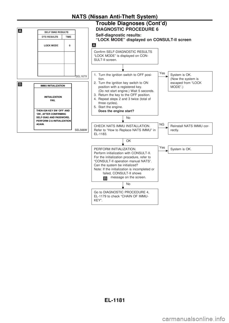
DIAGNOSTIC PROCEDURE 6
Self-diagnostic results:
ªLOCK MODEº displayed on CONSULT-II screen
Confirm SELF-DIAGNOSTIC RESULTS
ªLOCK MODEº is displayed on CON-
SULT-II screen.
1. Turn the ignition switch to OFF posi-
tion.
2. Turn the ignition key switch to ON
position with a registered key.
(Do not start engine.) Wait 5 seconds.
3. Return the key to the OFF position.
4. Repeat steps 2 and 3 twice (total of
three cycles).
5. Start the engine.
Does the engine start?
No
cYes
System is OK.
(Now the system is
escaped from ªLOCK
MODEº.)
CHECK NATS IMMU INSTALLATION.
Refer to ªHow to Replace NATS IMMUº in
EL-1183.
OK
cNG
Reinstall NATS IMMU cor-
rectly.
PERFORM INITIALIZATION.
Perform initialization with CONSULT-II.
For the initialization procedure, refer to
ªCONSULT-II operation manual NATSº.
Can the system be initialized?
Note: If the initialization is incompleted or
failed, CONSULT-II shows
message on the screen.
No
cYes
System is OK.
Go to DIAGNOSTIC PROCEDURE 4,
EL-1179 to check ªCHAIN OF IMMU-
KEYº.
SEL167X
SEL566W
.
.
.
.
NATS (Nissan Anti-Theft System)
Trouble Diagnoses (Cont'd)
EL-1181
Page 692 of 1033
![NISSAN PATROL 2000 Electronic Repair Manual DIAGNOSTIC PROCEDURE 7
ªSECURITY IND. DOES NOT LIGHT UPº
Check 7.5A fuse [No.24, located in the
fuse block (J/B)].
OK
cNG
Replace fuse.
NATS INITIALIZATION
1) Install the 7.5A fuse.
2) Perform initi NISSAN PATROL 2000 Electronic Repair Manual DIAGNOSTIC PROCEDURE 7
ªSECURITY IND. DOES NOT LIGHT UPº
Check 7.5A fuse [No.24, located in the
fuse block (J/B)].
OK
cNG
Replace fuse.
NATS INITIALIZATION
1) Install the 7.5A fuse.
2) Perform initi](/manual-img/5/57367/w960_57367-691.png)
DIAGNOSTIC PROCEDURE 7
ªSECURITY IND. DOES NOT LIGHT UPº
Check 7.5A fuse [No.24, located in the
fuse block (J/B)].
OK
cNG
Replace fuse.
NATS INITIALIZATION
1) Install the 7.5A fuse.
2) Perform initialization with CON-
SULT-II.
For the operation of
initialization, refer to ªCON-
SULT-II operation manual
NATSº.
Turn ignition switch ªOFFº.
Start engine and turn ignition switch
ªOFFº.
Check the security ind. lighting.
NG
cOK
END
Check voltage between security ind. con-
nector terminal
V1and ground.
Voltage: Battery voltage
OK
cNG
Check harness for open or
short between fuse and
security ind.
CHECK INDICATOR LAMP.
OK
cNG
Repair harness.
CHECK NATS IMMU FUNCTION.
1. Connect NATS IMMU connector.
2. Disconnect security ind. connector.
3. Check continuity between NATS IMMU
terminal
V6and ground.
Continuity should exist intermit-
tently.
OK
cNG
NATS IMMU is malfunc-
tioning. Replace IMMU.
Perform initializa-
tion with CON-
SULT-II.
For the operation
of initialization,
refer to ªCON-
SULT-II operation
manual NATSº.
Check harness for open or short between
security indicator and NATS IMMU.
SEL931UA
SEL164X
.
.
.
.
.
.
.
.
.
NATS (Nissan Anti-Theft System)
Trouble Diagnoses (Cont'd)
EL-1182
Page 747 of 1033
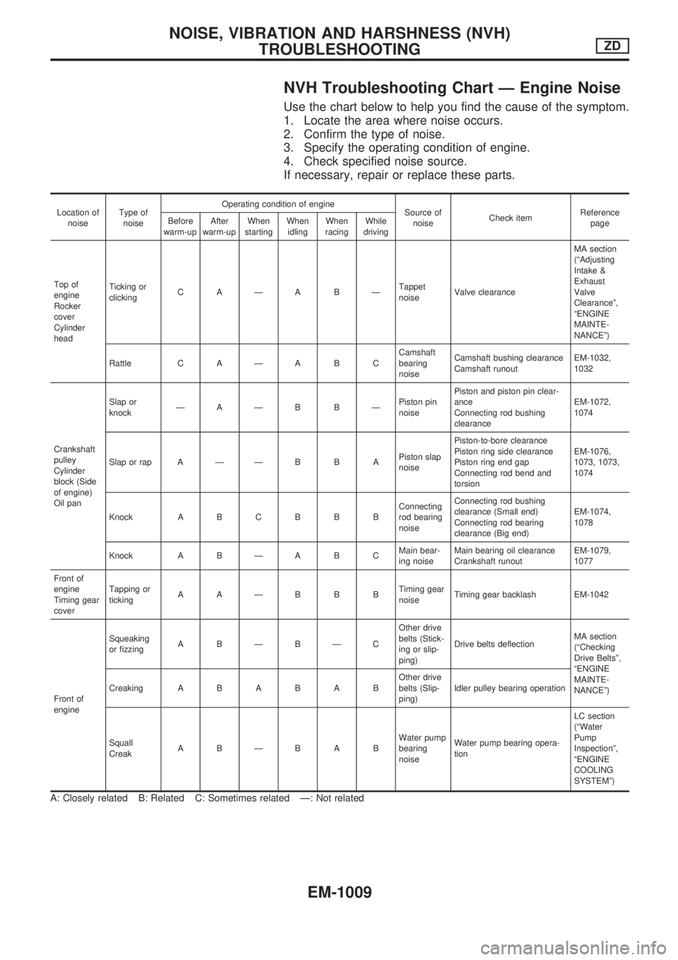
NVH Troubleshooting Chart Ð Engine Noise
Use the chart below to help you find the cause of the symptom.
1. Locate the area where noise occurs.
2. Confirm the type of noise.
3. Specify the operating condition of engine.
4. Check specified noise source.
If necessary, repair or replace these parts.
Location of
noiseType of
noiseOperating condition of engine
Source of
noiseCheck itemReference
page Before
warm-upAfter
warm-upWhen
startingWhen
idlingWhen
racingWhile
driving
Top of
engine
Rocker
cover
Cylinder
headTicking or
clickingCAÐABÐTappet
noiseValve clearanceMA section
(ªAdjusting
Intake &
Exhaust
Valve
Clearanceº,
ªENGINE
MAINTE-
NANCEº)
Rattle C A Ð A B CCamshaft
bearing
noiseCamshaft bushing clearance
Camshaft runoutEM-1032,
1032
Crankshaft
pulley
Cylinder
block (Side
of engine)
Oil panSlap or
knockÐAÐB BÐPiston pin
noisePiston and piston pin clear-
ance
Connecting rod bushing
clearanceEM-1072,
1074
Slap or rap A Ð Ð B B APiston slap
noisePiston-to-bore clearance
Piston ring side clearance
Piston ring end gap
Connecting rod bend and
torsionEM-1076,
1073, 1073,
1074
Knock A B C B B BConnecting
rod bearing
noiseConnecting rod bushing
clearance (Small end)
Connecting rod bearing
clearance (Big end)EM-1074,
1078
Knock A B Ð A B CMain bear-
ing noiseMain bearing oil clearance
Crankshaft runoutEM-1079,
1077
Front of
engine
Timing gear
coverTapping or
tickingAAÐBBBTiming gear
noiseTiming gear backlash EM-1042
Front of
engineSqueaking
or fizzingABÐBÐCOther drive
belts (Stick-
ing or slip-
ping)Drive belts deflectionMA section
(ªChecking
Drive Beltsº,
ªENGINE
MAINTE-
NANCEº) CreakingABABABOther drive
belts (Slip-
ping)Idler pulley bearing operation
Squall
CreakABÐBABWater pump
bearing
noiseWater pump bearing opera-
tionLC section
(ªWater
Pump
Inspectionº,
ªENGINE
COOLING
SYSTEMº)
A: Closely related B: Related C: Sometimes related Ð: Not related
NOISE, VIBRATION AND HARSHNESS (NVH)
TROUBLESHOOTINGZD
EM-1009
Page 748 of 1033
1. Warm up engine.
2. Turn ignition switch OFF.
3.
Using CONSULT-II, make sure no error codes are indicated for
self-diagnosis items. Refer to EC section, ªFuel Pressure
Releaseº.
+Do not disconnect CONSULT-II until the end of this opera-
tion; it will be used to check engine rpm and for error detec-
tion at the end of this operation.
4. Disconnect the negative battery terminal.
5. Remove the following parts.
+Intercooler cover
+Intercooler
+Throttle body
+Rocker cover
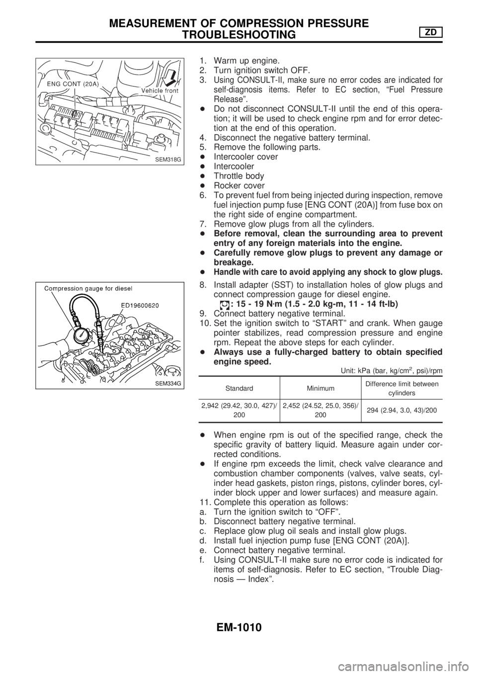
6. To prevent fuel from being injected during inspection, remove
fuel injection pump fuse [ENG CONT (20A)] from fuse box on
the right side of engine compartment.
7. Remove glow plugs from all the cylinders.
+Before removal, clean the surrounding area to prevent
entry of any foreign materials into the engine.
+Carefully remove glow plugs to prevent any damage or
breakage.
+
Handle with care to avoid applying any shock to glow plugs.
8. Install adapter (SST) to installation holes of glow plugs and
connect compression gauge for diesel engine.
:15-19Nzm (1.5 - 2.0 kg-m, 11 - 14 ft-lb)
9. Connect battery negative terminal.
10. Set the ignition switch to ªSTARTº and crank. When gauge
pointer stabilizes, read compression pressure and engine
rpm. Repeat the above steps for each cylinder.
+Always use a fully-charged battery to obtain specified
engine speed.
Unit: kPa (bar, kg/cm2, psi)/rpm
Standard MinimumDifference limit between
cylinders
2,942 (29.42, 30.0, 427)/
2002,452 (24.52, 25.0, 356)/
200294 (2.94, 3.0, 43)/200
+When engine rpm is out of the specified range, check the
specific gravity of battery liquid. Measure again under cor-
rected conditions.
+If engine rpm exceeds the limit, check valve clearance and
combustion chamber components (valves, valve seats, cyl-
inder head gaskets, piston rings, pistons, cylinder bores, cyl-
inder block upper and lower surfaces) and measure again.
11. Complete this operation as follows:
a. Turn the ignition switch to ªOFFº.
b. Disconnect battery negative terminal.
c. Replace glow plug oil seals and install glow plugs.
d. Install fuel injection pump fuse [ENG CONT (20A)].
e. Connect battery negative terminal.
f. Using CONSULT-II make sure no error code is indicated for
items of self-diagnosis. Refer to EC section, ªTrouble Diag-
nosis Ð Indexº.
SEM318G
SEM334G
MEASUREMENT OF COMPRESSION PRESSURE
TROUBLESHOOTINGZD
EM-1010