Page 433 of 1033
Description
The ECM consists of a microcomputer and connectors for signal
input and output and for power supply. The unit controls the
engine.
On Board Diagnosis Logic
Malfunction is detected when ... Check Items (Possible Cause)
+ECM input signal processing function is malfunctioning.+ECM
(ECCS-D control module)
DTC Confirmation Procedure
WITH CONSULT-II
1) Turn ignition switch ªONº.
2) Select ªDATA MONITORº mode with CONSULT-II.
3) Turn ignition switch ªOFFº, wait at least 20 seconds and then
turn ªONº.
4) If DTC is detected, go to ªDiagnostic Procedureº, EC-1201.
WITHOUT CONSULT-II
1) Turn ignition switch ªONº and wait at least 2 seconds.
2) Turn ignition switch ªOFFº, wait at least 20 seconds and then
turn ªONº.
3) Perform ªDiagnostic Test Mode II (Self-diagnostic results)º
with ECM.
4) If DTC is detected, go to ªDiagnostic Procedureº, EC-1201.
SEC220B
SEF817Y
DTC 0903 ECM 15ZD30DDTi
EC-1200
Page 435 of 1033
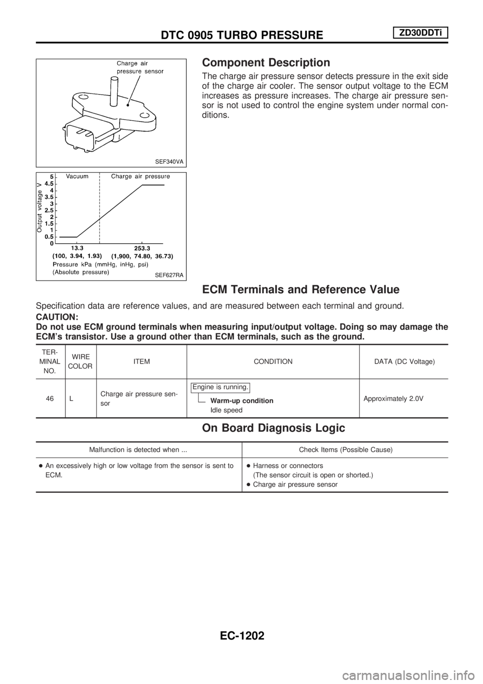
Component Description
The charge air pressure sensor detects pressure in the exit side
of the charge air cooler. The sensor output voltage to the ECM
increases as pressure increases. The charge air pressure sen-
sor is not used to control the engine system under normal con-
ditions.
ECM Terminals and Reference Value
Specification data are reference values, and are measured between each terminal and ground.
CAUTION:
Do not use ECM ground terminals when measuring input/output voltage. Doing so may damage the
ECM's transistor. Use a ground other than ECM terminals, such as the ground.
TER-
MINAL
NO.WIRE
COLORITEM CONDITION DATA (DC Voltage)
46 LCharge air pressure sen-
sorEngine is running.
Warm-up condition
Idle speedApproximately 2.0V
On Board Diagnosis Logic
Malfunction is detected when ... Check Items (Possible Cause)
+An excessively high or low voltage from the sensor is sent to
ECM.+Harness or connectors
(The sensor circuit is open or shorted.)
+Charge air pressure sensor
SEF340VA
SEF627RA
DTC 0905 TURBO PRESSUREZD30DDTi
EC-1202
Page 438 of 1033
Diagnostic Procedure
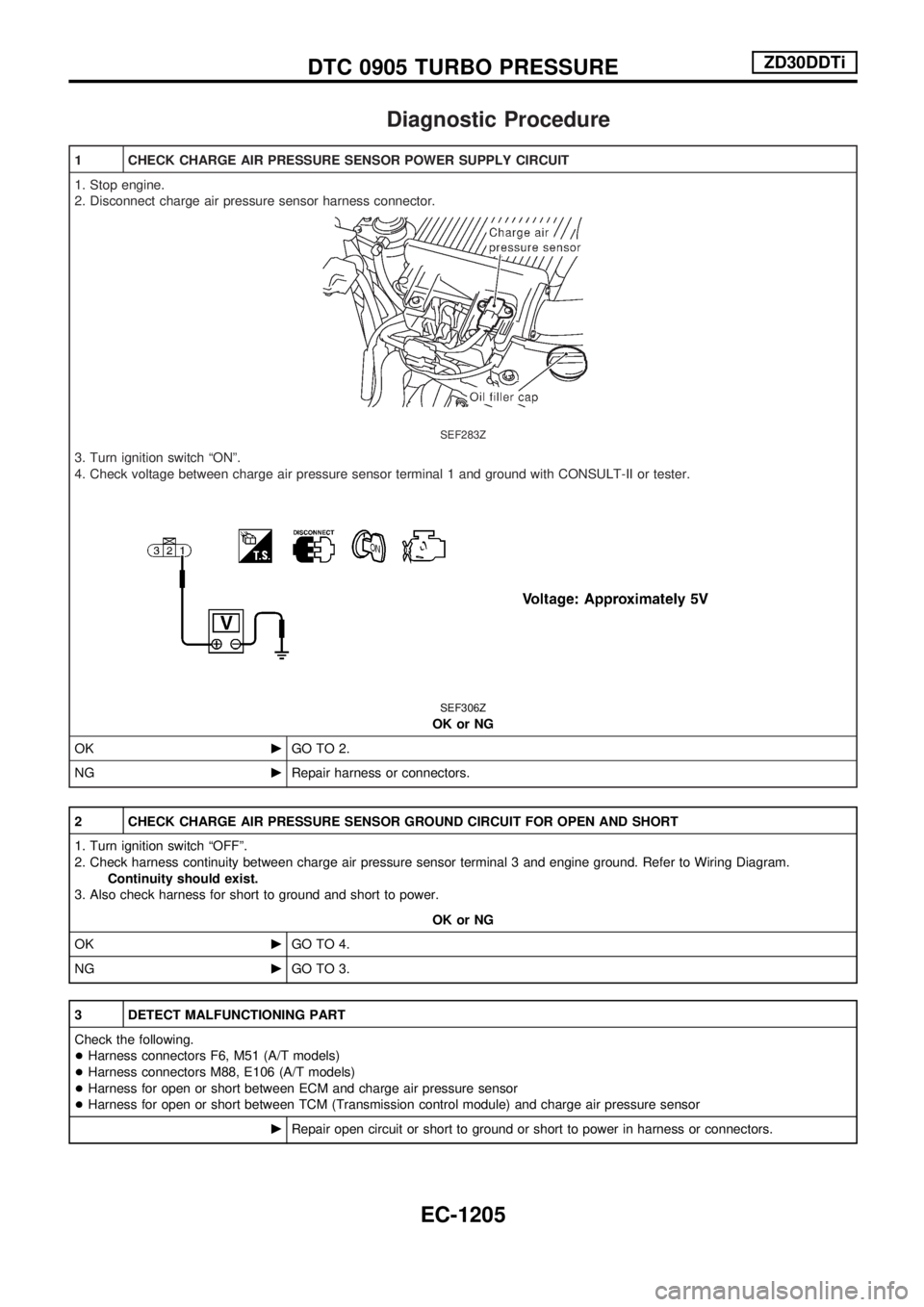
1 CHECK CHARGE AIR PRESSURE SENSOR POWER SUPPLY CIRCUIT
1. Stop engine.
2. Disconnect charge air pressure sensor harness connector.
SEF283Z
3. Turn ignition switch ªONº.
4. Check voltage between charge air pressure sensor terminal 1 and ground with CONSULT-II or tester.
SEF306Z
OK or NG
OKcGO TO 2.
NGcRepair harness or connectors.
2 CHECK CHARGE AIR PRESSURE SENSOR GROUND CIRCUIT FOR OPEN AND SHORT
1. Turn ignition switch ªOFFº.
2. Check harness continuity between charge air pressure sensor terminal 3 and engine ground. Refer to Wiring Diagram.
Continuity should exist.
3. Also check harness for short to ground and short to power.
OK or NG
OKcGO TO 4.
NGcGO TO 3.
3 DETECT MALFUNCTIONING PART
Check the following.
+Harness connectors F6, M51 (A/T models)
+Harness connectors M88, E106 (A/T models)
+Harness for open or short between ECM and charge air pressure sensor
+Harness for open or short between TCM (Transmission control module) and charge air pressure sensor
cRepair open circuit or short to ground or short to power in harness or connectors.
DTC 0905 TURBO PRESSUREZD30DDTi
EC-1205
Page 439 of 1033
4 CHECK CHARGE AIR PRESSURE SENSOR INPUT SIGNAL CIRCUIT FOR OPEN AND SHORT
1. Disconnect ECM harness connector.
2. Check harness continuity between ECM terminal 46 and charge air pressure sensor terminal 2. Refer to Wiring Diagram.
Continuity should exist.
3. Also check harness for short to ground and short to power.
OK or NG
OKcGO TO 5.
NGcRepair open circuit or short to ground or short to power in harness or connectors.
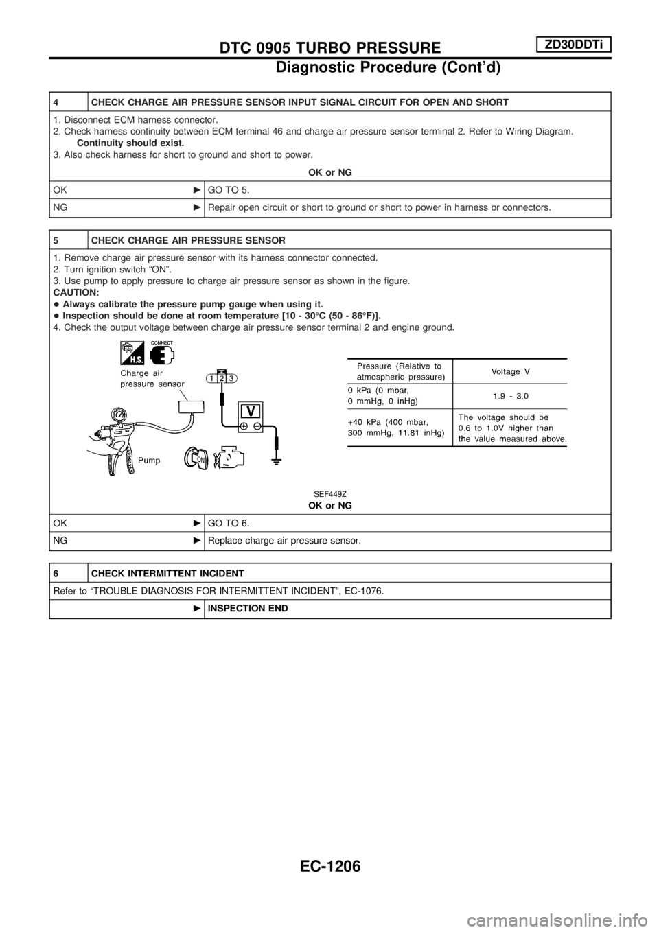
5 CHECK CHARGE AIR PRESSURE SENSOR
1. Remove charge air pressure sensor with its harness connector connected.
2. Turn ignition switch ªONº.
3. Use pump to apply pressure to charge air pressure sensor as shown in the figure.
CAUTION:
+Always calibrate the pressure pump gauge when using it.
+Inspection should be done at room temperature [10 - 30ÉC (50 - 86ÉF)].
4. Check the output voltage between charge air pressure sensor terminal 2 and engine ground.
SEF449Z
OK or NG
OKcGO TO 6.
NGcReplace charge air pressure sensor.
6 CHECK INTERMITTENT INCIDENT
Refer to ªTROUBLE DIAGNOSIS FOR INTERMITTENT INCIDENTº, EC-1076.
cINSPECTION END
DTC 0905 TURBO PRESSUREZD30DDTi
Diagnostic Procedure (Cont'd)
EC-1206
Page 449 of 1033
CONSULT-II Reference Value in Data Monitor
Mode
Remarks: Specification data are reference values.
MONITOR ITEM CONDITION SPECIFICATION
FUEL TEMP SEN+Engine: After warming up More than 40ÉC (104ÉF)
SPILL/V+Engine: After warming up Approx. 13ÉCA
INJ TIMG C/V+Engine: After warming up,
idle the engine.Approx. 50 - 70%
DECELER F/CUT+Engine: After warm-
ing upIdle OFF
BARO SEN+Ignition switch: ONAltitude
Approx.0m(0ft): Approx. 100.62 kPa (1.0062 bar, 1.026 kg/cm
2, 14.59
psi)
Approx. 1,000 m (3,281 ft): Approx. 88.95 kPa (0.8895 bar, 0.907 kg/cm
2,
12.90 psi)
Approx. 1,500 m (4,992 ft): Approx. 83.16 kPa (0.8316 bar, 0.848 kg/cm
2,
12.06 psi)
Approx. 2,000 m (6,562 ft): Approx. 78.36 kPa (0.7836 bar, 0.799 kg/cm
2,
11.36 psi)
ECM Terminals and Reference Value
Specification data are reference values and are measured between each terminal and ground.
CAUTION:
Do not use ECM ground terminals when measuring input/output voltage. Doing so may damage the
ECM's transistor. Use a ground other than ECM terminals, such as the ground.
TER-
MINAL
NO.WIRE
COLORITEM CONDITION DATA (DC Voltage)
33 G/YElectronic control fuel
injection pumpEngine is running.
Warm-up condition
Idle speedApproximately 2.5V
40 R/BElectronic control fuel
injection pumpEngine is running.
Warm-up condition
Idle speedApproximately 2.5V
52 L/BElectronic control fuel
injection pumpEngine is running.
Idle speedApproximately 0.1V
53 L/RElectronic control fuel
injection pumpEngine is running.
Idle speedApproximately 0.35V
On Board Diagnosis Logic
Malfunction is detected when .... Check Items (Possible cause)
+Fuel cut control system does not function properly.+Harness or connectors
(Electronic control fuel circuit is open or shorted.)
+Electronic control fuel
DTC 1004 FUEL CUT SYSTEM1ZD30DDTi
EC-1216
Page 453 of 1033
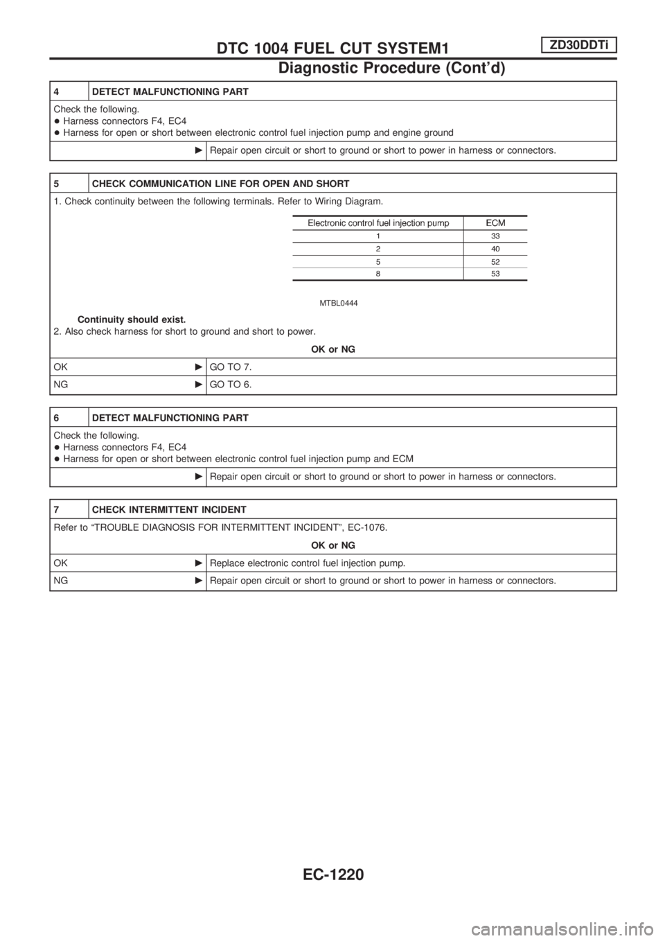
4 DETECT MALFUNCTIONING PART
Check the following.
+Harness connectors F4, EC4
+Harness for open or short between electronic control fuel injection pump and engine ground
cRepair open circuit or short to ground or short to power in harness or connectors.
5 CHECK COMMUNICATION LINE FOR OPEN AND SHORT
1. Check continuity between the following terminals. Refer to Wiring Diagram.
MTBL0444
Continuity should exist.
2. Also check harness for short to ground and short to power.
OK or NG
OKcGO TO 7.
NGcGO TO 6.
6 DETECT MALFUNCTIONING PART
Check the following.
+Harness connectors F4, EC4
+Harness for open or short between electronic control fuel injection pump and ECM
cRepair open circuit or short to ground or short to power in harness or connectors.
7 CHECK INTERMITTENT INCIDENT
Refer to ªTROUBLE DIAGNOSIS FOR INTERMITTENT INCIDENTº, EC-1076.
OK or NG
OKcReplace electronic control fuel injection pump.
NGcRepair open circuit or short to ground or short to power in harness or connectors.
DTC 1004 FUEL CUT SYSTEM1ZD30DDTi
Diagnostic Procedure (Cont'd)
EC-1220
Page 457 of 1033
Diagnostic Procedure
1 INSPECTION START
Check fuel level, fuel supplying system, starter motor, etc.
OK or NG
OKcGO TO 2.
NGcCorrect.
2 CHECK INSTALLATION
Check that all glow plug connecting plate nuts are installed properly.
SEF233Z
OK or NG
OK (With CONSULT-II)cGO TO 3.
OK (Without CONSULT-II)cGO TO 4.
NGcInstall properly.
3 CHECK GLOW INDICATOR LAMP OPERATION
With CONSULT-II
1. Turn ignition switch ªONº.
2. Select ªCOOLAN TEMP/Sº in ªDATA MONITORº mode with CONSULT-II.
3. Confirm that ªCOOLAN TEMP/Sº indicates below 75ÉC (167ÉF). If it indicates above 75ÉC (167ÉF), cool down engine.
SEF013Y
4. Turn ignition switch ªOFFº, wait at least 5 seconds and then turn ªONº.
5. Make sure that glow indicator lamp is turned ªONº for 1.5 seconds or more after turning ignition switch ªONº, and then turned
ªOFFº.
OK or NG
OKcGO TO 5.
NGcGO TO 6.
GLOW CONTROL SYSTEMZD30DDTi
EC-1224
Page 458 of 1033
4 CHECK GLOW INDICATOR LAMP OPERATION
Without CONSULT-II
1. Turn ignition switch ªONº.
2. Confirm that the voltage between ECM terminal 19 and ground is above 1.36V. If it is below 1.36V, cool down engine.
SEF430Y
3. Turn ignition switch ªOFFº, wait at least 5 seconds and then turn ªONº.
4. Make sure that glow indicator lamp is turned ªONº for 1.5 seconds or more after turning ignition switch ªONº, and then turned
ªOFFº.
OK or NG
OKcGO TO 5.
NGcGO TO 6.
5 CHECK GLOW CONTROL SYSTEM OVERALL FUNCTION
1. Turn ignition switch ªOFFº.
2. Set voltmeter probe between glow plug and engine body.
3. Turn ignition switch ªONº.
4. Check the voltage between glow plug and engine body under the following conditions.
SEF234Z
OK or NG
OKcINSPECTION END
NGcGO TO 11.
GLOW CONTROL SYSTEMZD30DDTi
Diagnostic Procedure (Cont'd)
EC-1225