Page 340 of 1033
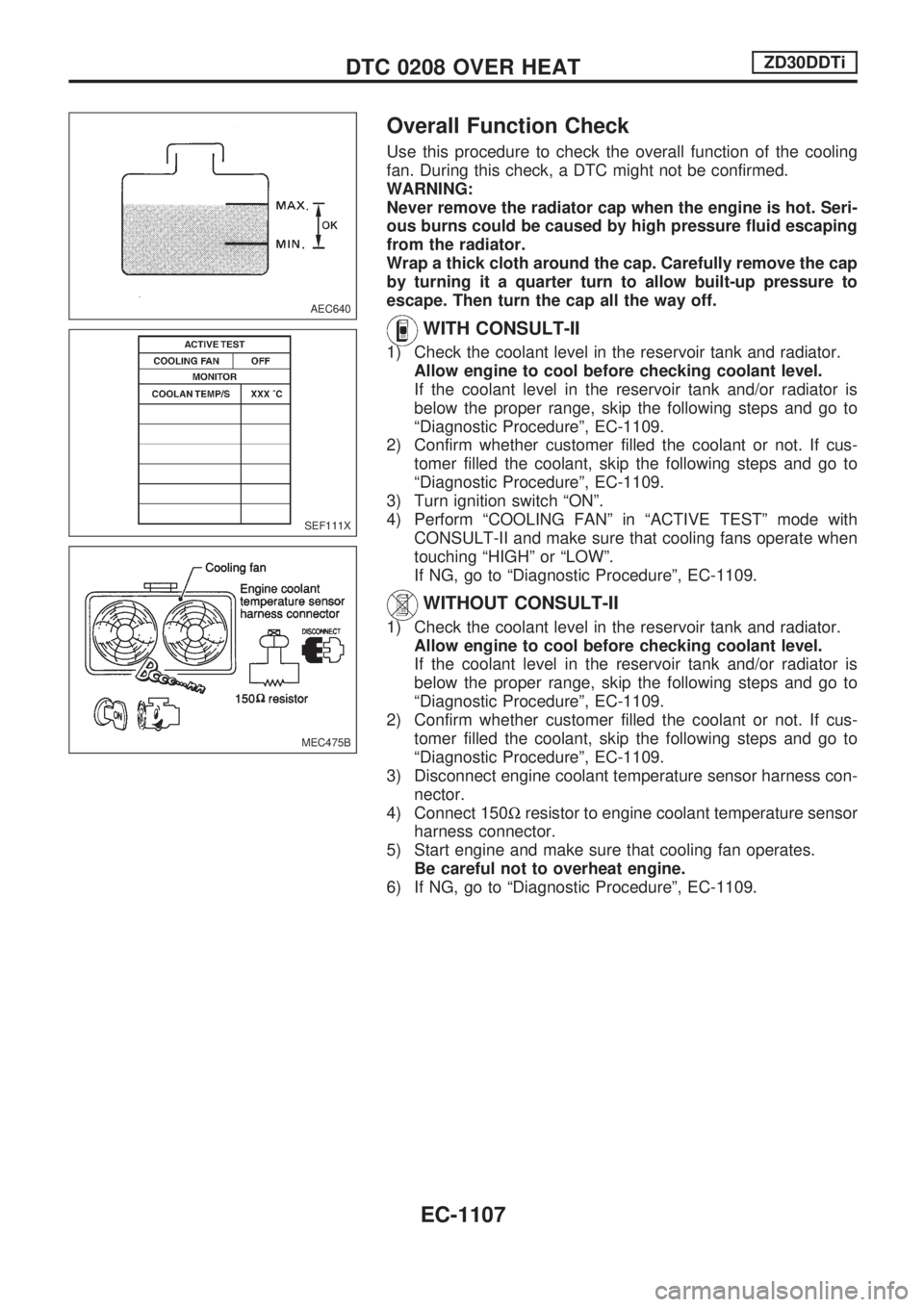
Overall Function Check
Use this procedure to check the overall function of the cooling
fan. During this check, a DTC might not be confirmed.
WARNING:
Never remove the radiator cap when the engine is hot. Seri-
ous burns could be caused by high pressure fluid escaping
from the radiator.
Wrap a thick cloth around the cap. Carefully remove the cap
by turning it a quarter turn to allow built-up pressure to
escape. Then turn the cap all the way off.
WITH CONSULT-II
1) Check the coolant level in the reservoir tank and radiator.
Allow engine to cool before checking coolant level.
If the coolant level in the reservoir tank and/or radiator is
below the proper range, skip the following steps and go to
ªDiagnostic Procedureº, EC-1109.
2) Confirm whether customer filled the coolant or not. If cus-
tomer filled the coolant, skip the following steps and go to
ªDiagnostic Procedureº, EC-1109.
3) Turn ignition switch ªONº.
4) Perform ªCOOLING FANº in ªACTIVE TESTº mode with
CONSULT-II and make sure that cooling fans operate when
touching ªHIGHº or ªLOWº.
If NG, go to ªDiagnostic Procedureº, EC-1109.
WITHOUT CONSULT-II
1) Check the coolant level in the reservoir tank and radiator.
Allow engine to cool before checking coolant level.
If the coolant level in the reservoir tank and/or radiator is
below the proper range, skip the following steps and go to
ªDiagnostic Procedureº, EC-1109.
2) Confirm whether customer filled the coolant or not. If cus-
tomer filled the coolant, skip the following steps and go to
ªDiagnostic Procedureº, EC-1109.
3) Disconnect engine coolant temperature sensor harness con-
nector.
4) Connect 150Wresistor to engine coolant temperature sensor
harness connector.
5) Start engine and make sure that cooling fan operates.
Be careful not to overheat engine.
6) If NG, go to ªDiagnostic Procedureº, EC-1109.
AEC640
SEF111X
MEC475B
DTC 0208 OVER HEATZD30DDTi
EC-1107
Page 343 of 1033
3 CHECK COOLING FAN OPERATION
Without CONSULT-II
1. Turn ignition switch ªOFFº.
2. Disconnect engine coolant temperature sensor harness connector.
3. Connect 150Wresistor to engine coolant temperature sensor harness connector.
4. Restart engine and make sure that cooling fan operates.
MEC475B
OK or NG
OKcGO TO 12.
NGcGO TO 4.
DTC 0208 OVER HEATZD30DDTi
Diagnostic Procedure (Cont'd)
EC-1110
Page 348 of 1033
15 CHECK THERMOSTAT
1. Remove thermostat.
2. Check valve seating condition at normal room temperatures.
It should seat tightly.
3. Check valve opening temperature and valve lift.
SLC343
Valve opening temperature:
82ÉC (180ÉF) [standard] (Models for cold areas)
76.5ÉC (170ÉF) [standard] (Models for except cold areas)
Valve lift:
More than 10 mm/95ÉC (0.394 in/203ÉF)
4. Check if valve is closed at 5ÉC (9ÉF) below valve opening temperature. For details, refer to LC section, ªThermostatº.
OK or NG
OKcGO TO 16.
NGcReplace thermostat.
16 CHECK ENGINE COOLANT TEMPERATURE SENSOR
1. Remove engine coolant temperature sensor.
2. Check resistance between engine coolant temperature sensor terminals 1 and 2 as shown in the figure.
SEF304X
OK or NG
OKcGO TO 17.
NGcReplace engine coolant temperature sensor.
DTC 0208 OVER HEATZD30DDTi
Diagnostic Procedure (Cont'd)
EC-1115
Page 349 of 1033
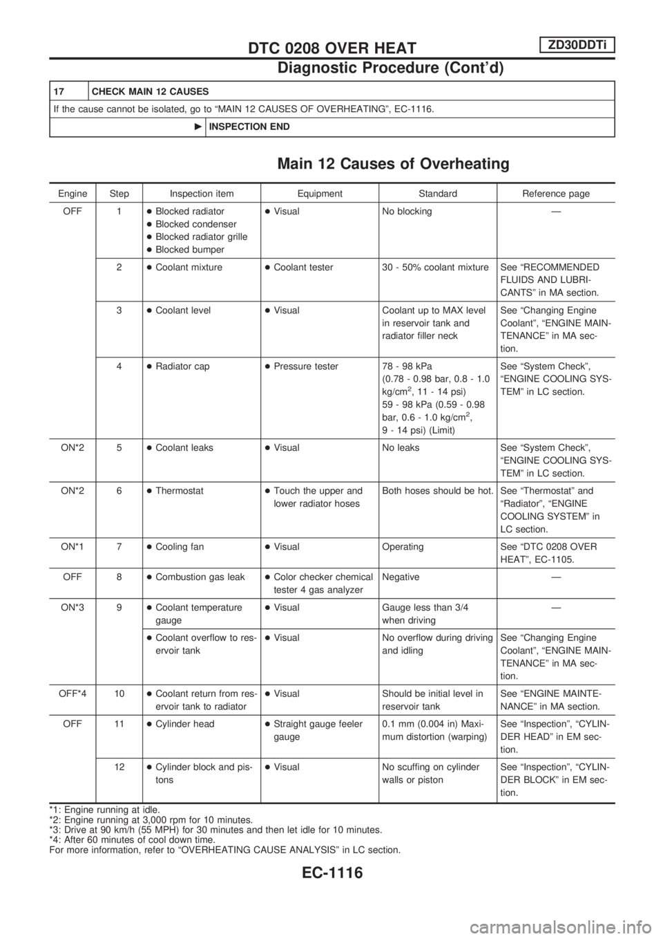
17 CHECK MAIN 12 CAUSES
If the cause cannot be isolated, go to ªMAIN 12 CAUSES OF OVERHEATINGº, EC-1116.
cINSPECTION END
Main 12 Causes of Overheating
Engine Step Inspection item Equipment Standard Reference page
OFF 1+Blocked radiator
+Blocked condenser
+Blocked radiator grille
+Blocked bumper+Visual No blocking Ð
2+Coolant mixture+Coolant tester 30 - 50% coolant mixture See ªRECOMMENDED
FLUIDS AND LUBRI-
CANTSº in MA section.
3+Coolant level+Visual Coolant up to MAX level
in reservoir tank and
radiator filler neckSee ªChanging Engine
Coolantº, ªENGINE MAIN-
TENANCEº in MA sec-
tion.
4+Radiator cap+Pressure tester 78 - 98 kPa
(0.78 - 0.98 bar, 0.8 - 1.0
kg/cm
2, 11 - 14 psi)
59 - 98 kPa (0.59 - 0.98
bar, 0.6 - 1.0 kg/cm
2,
9 - 14 psi) (Limit)See ªSystem Checkº,
ªENGINE COOLING SYS-
TEMº in LC section.
ON*2 5+Coolant leaks+Visual No leaks See ªSystem Checkº,
ªENGINE COOLING SYS-
TEMº in LC section.
ON*2 6+Thermostat+Touch the upper and
lower radiator hosesBoth hoses should be hot. See ªThermostatº and
ªRadiatorº, ªENGINE
COOLING SYSTEMº in
LC section.
ON*1 7+Cooling fan+Visual Operating See ªDTC 0208 OVER
HEATº, EC-1105.
OFF 8+Combustion gas leak+Color checker chemical
tester 4 gas analyzerNegative Ð
ON*3 9+Coolant temperature
gauge+Visual Gauge less than 3/4
when drivingÐ
+Coolant overflow to res-
ervoir tank+Visual No overflow during driving
and idlingSee ªChanging Engine
Coolantº, ªENGINE MAIN-
TENANCEº in MA sec-
tion.
OFF*4 10+Coolant return from res-
ervoir tank to radiator+Visual Should be initial level in
reservoir tankSee ªENGINE MAINTE-
NANCEº in MA section.
OFF 11+Cylinder head+Straight gauge feeler
gauge0.1 mm (0.004 in) Maxi-
mum distortion (warping)See ªInspectionº, ªCYLIN-
DER HEADº in EM sec-
tion.
12+Cylinder block and pis-
tons+Visual No scuffing on cylinder
walls or pistonSee ªInspectionº, ªCYLIN-
DER BLOCKº in EM sec-
tion.
*1: Engine running at idle.
*2: Engine running at 3,000 rpm for 10 minutes.
*3: Drive at 90 km/h (55 MPH) for 30 minutes and then let idle for 10 minutes.
*4: After 60 minutes of cool down time.
For more information, refer to ªOVERHEATING CAUSE ANALYSISº in LC section.
DTC 0208 OVER HEATZD30DDTi
Diagnostic Procedure (Cont'd)
EC-1116
Page 350 of 1033
Description
The ECM consists of a microcomputer and connectors for signal
input and output and for power supply. The unit controls the
engine.
On Board Diagnosis Logic
Malfunction is detected when ... Check Items (Possible Cause)
+ECM calculation function is malfunctioning.+ECM
(ECCS-D control module)
DTC Confirmation Procedure
WITH CONSULT-II
1) Turn ignition switch ªONº.
2) Select ªDATA MONITORº mode with CONSULT-II.
3) Start engine and wait at least 2 seconds.
4) If DTC is detected, go to ªDiagnostic Procedureº, EC-1118.
WITHOUT CONSULT-II
1) Turn ignition switch ªONº and wait at least 2 seconds.
2) Start engine and wait at least 2 seconds.
3) Turn ignition switch ªOFFº, wait at least 5 seconds and then
turn ªONº.
4) Perform ªDiagnostic Test Mode II (Self-diagnostic results)º
with ECM.
5) If DTC is detected, go to ªDiagnostic Procedureº, EC-1118.
SEC220B
SEF817Y
DTC 0301 ECM 2, DTC 0901 ECM 12ZD30DDTi
EC-1117
Page 353 of 1033
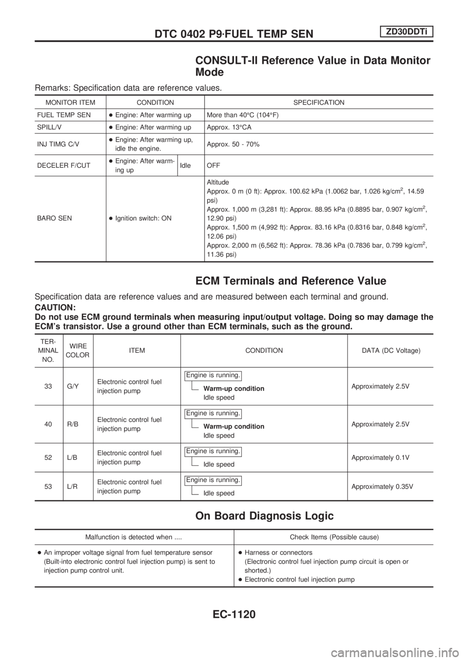
CONSULT-II Reference Value in Data Monitor
Mode
Remarks: Specification data are reference values.
MONITOR ITEM CONDITION SPECIFICATION
FUEL TEMP SEN+Engine: After warming up More than 40ÉC (104ÉF)
SPILL/V+Engine: After warming up Approx. 13ÉCA
INJ TIMG C/V+Engine: After warming up,
idle the engine.Approx. 50 - 70%
DECELER F/CUT+Engine: After warm-
ing upIdle OFF
BARO SEN+Ignition switch: ONAltitude
Approx.0m(0ft): Approx. 100.62 kPa (1.0062 bar, 1.026 kg/cm
2, 14.59
psi)
Approx. 1,000 m (3,281 ft): Approx. 88.95 kPa (0.8895 bar, 0.907 kg/cm
2,
12.90 psi)
Approx. 1,500 m (4,992 ft): Approx. 83.16 kPa (0.8316 bar, 0.848 kg/cm
2,
12.06 psi)
Approx. 2,000 m (6,562 ft): Approx. 78.36 kPa (0.7836 bar, 0.799 kg/cm
2,
11.36 psi)
ECM Terminals and Reference Value
Specification data are reference values and are measured between each terminal and ground.
CAUTION:
Do not use ECM ground terminals when measuring input/output voltage. Doing so may damage the
ECM's transistor. Use a ground other than ECM terminals, such as the ground.
TER-
MINAL
NO.WIRE
COLORITEM CONDITION DATA (DC Voltage)
33 G/YElectronic control fuel
injection pumpEngine is running.
Warm-up condition
Idle speedApproximately 2.5V
40 R/BElectronic control fuel
injection pumpEngine is running.
Warm-up condition
Idle speedApproximately 2.5V
52 L/BElectronic control fuel
injection pumpEngine is running.
Idle speedApproximately 0.1V
53 L/RElectronic control fuel
injection pumpEngine is running.
Idle speedApproximately 0.35V
On Board Diagnosis Logic
Malfunction is detected when .... Check Items (Possible cause)
+An improper voltage signal from fuel temperature sensor
(Built-into electronic control fuel injection pump) is sent to
injection pump control unit.+Harness or connectors
(Electronic control fuel injection pump circuit is open or
shorted.)
+Electronic control fuel injection pump
DTC 0402 P9zFUEL TEMP SENZD30DDTi
EC-1120
Page 357 of 1033
4 DETECT MALFUNCTIONING PART
Check the following.
+Harness connectors F4, EC4
+Harness for open or short between electronic control fuel injection pump and engine ground
cRepair open circuit or short to ground or short to power in harness or connectors.
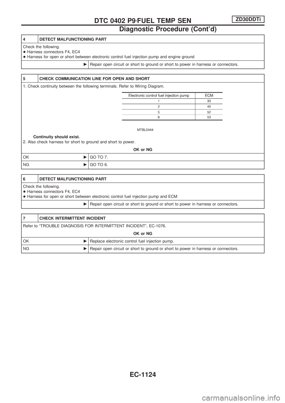
5 CHECK COMMUNICATION LINE FOR OPEN AND SHORT
1. Check continuity between the following terminals. Refer to Wiring Diagram.
MTBL0444
Continuity should exist.
2. Also check harness for short to ground and short to power.
OK or NG
OKcGO TO 7.
NGcGO TO 6.
6 DETECT MALFUNCTIONING PART
Check the following.
+Harness connectors F4, EC4
+Harness for open or short between electronic control fuel injection pump and ECM
cRepair open circuit or short to ground or short to power in harness or connectors.
7 CHECK INTERMITTENT INCIDENT
Refer to ªTROUBLE DIAGNOSIS FOR INTERMITTENT INCIDENTº, EC-1076.
OK or NG
OKcReplace electronic control fuel injection pump.
NGcRepair open circuit or short to ground or short to power in harness or connectors.
DTC 0402 P9zFUEL TEMP SENZD30DDTi
Diagnostic Procedure (Cont'd)
EC-1124
Page 359 of 1033
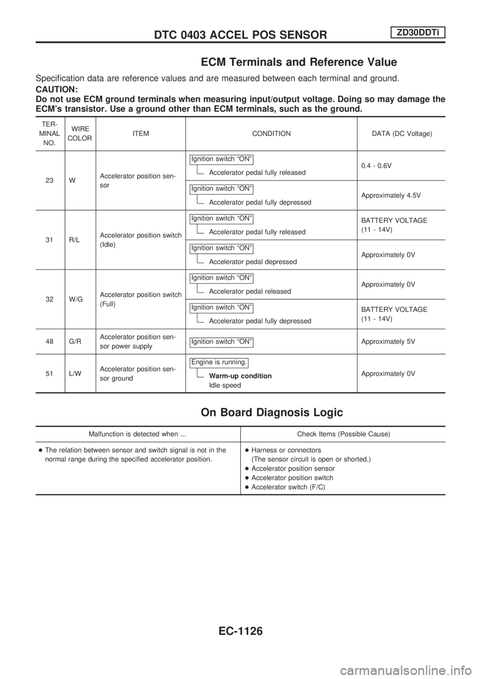
ECM Terminals and Reference Value
Specification data are reference values and are measured between each terminal and ground.
CAUTION:
Do not use ECM ground terminals when measuring input/output voltage. Doing so may damage the
ECM's transistor. Use a ground other than ECM terminals, such as the ground.
TER-
MINAL
NO.WIRE
COLORITEM CONDITION DATA (DC Voltage)
23 WAccelerator position sen-
sorIgnition switch ªONº
Accelerator pedal fully released0.4 - 0.6V
Ignition switch ªONº
Accelerator pedal fully depressedApproximately 4.5V
31 R/LAccelerator position switch
(Idle)Ignition switch ªONº
Accelerator pedal fully releasedBATTERY VOLTAGE
(11 - 14V)
Ignition switch ªONº
Accelerator pedal depressedApproximately 0V
32 W/GAccelerator position switch
(Full)Ignition switch ªONº
Accelerator pedal releasedApproximately 0V
Ignition switch ªONº
Accelerator pedal fully depressedBATTERY VOLTAGE
(11 - 14V)
48 G/RAccelerator position sen-
sor power supplyIgnition switch ªONº
Approximately 5V
51 L/WAccelerator position sen-
sor groundEngine is running.
Warm-up condition
Idle speedApproximately 0V
On Board Diagnosis Logic
Malfunction is detected when ... Check Items (Possible Cause)
+The relation between sensor and switch signal is not in the
normal range during the specified accelerator position.+Harness or connectors
(The sensor circuit is open or shorted.)
+Accelerator position sensor
+Accelerator position switch
+Accelerator switch (F/C)
DTC 0403 ACCEL POS SENSORZD30DDTi
EC-1126