2000 NISSAN PATROL check engine
[x] Cancel search: check enginePage 755 of 1033
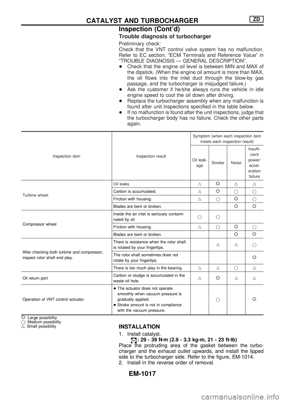
Trouble diagnosis of turbocharger
Preliminary check:
Check that the VNT control valve system has no malfunction.
Refer to EC section, ªECM Terminals and Reference Valueº in
ªTROUBLE DIAGNOSIS Ð GENERAL DESCRIPTIONº.
+Check that the engine oil level is between MIN and MAX of
the dipstick. (When the engine oil amount is more than MAX,
the oil flows into the inlet duct through the blow-by gas
passage, and the turbocharger is misjudged failure.)
+Ask the customer if he/she always runs the vehicle in idle
engine speed to cool the oil down after driving.
+Replace the turbocharger assembly when any malfunction is
found after unit inspections specified in the table below.
+If no malfunction is found after the unit inspections, judge that
the turbocharger body has no failure. Check the other parts
again.
Inspection item Inspection resultSymptom (when each inspection item
meets each inspection result)
Oil leak-
ageSmoke NoiseInsuffi-
cient
power/
accel-
eration
failure
Turbine wheelOil leaks.n
nn
Carbon is accumulated.n
jj
Friction with housing.nj
j
Blades are bent or broken.
Compressor wheelInside the air inlet is seriously contami-
nated by oil.jj
Friction with housing.njj
Blades are bent or broken.
After checking both turbine and compressor,
inspect rotor shaft end play.There is resistance when the rotor shaft
is rotated by your fingertips.nnj
The rotor shaft sometimes does not
rotate by your fingertips.
There is too much play in the bearing.nnjn
Oil return portCarbon or sludge is accumulated in the
waste oil hole.n
nn
Operation of VNT control actuator+The actuator does not operate
smoothly when vacuum pressure is
gradually applied.
+Stroke amount is not in compliance
with the vacuum pressure.j
: Large possibility
j: Medium possibility
n: Small possibility
INSTALLATION
1. Install catalyst.
:29-39Nzm (2.9 - 3.3 kg-m, 21 - 23 ft-lb)
Place the protruding area of the gasket between the turbo-
charger and the exhaust outlet upwards, and install the lipped
side to the turbocharger side. Refer to the figure, EM-1014.
2. Install in the reverse order of removal.
CATALYST AND TURBOCHARGERZD
Inspection (Cont'd)
EM-1017
Page 770 of 1033
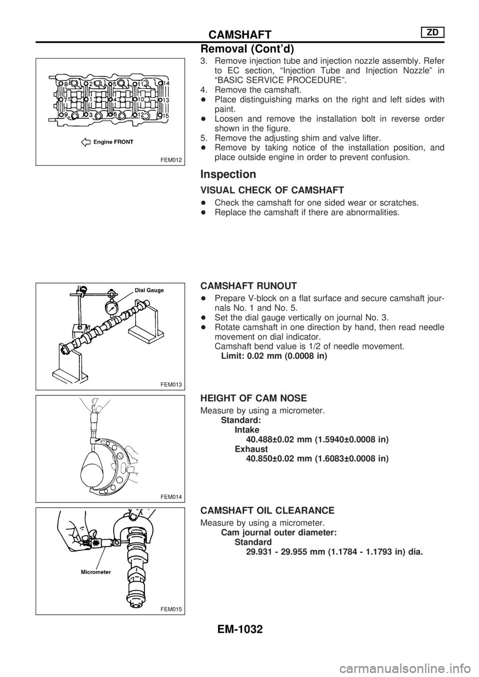
3. Remove injection tube and injection nozzle assembly. Refer
to EC section, ªInjection Tube and Injection Nozzleº in
ªBASIC SERVICE PROCEDUREº.
4. Remove the camshaft.
+Place distinguishing marks on the right and left sides with
paint.
+Loosen and remove the installation bolt in reverse order
shown in the figure.
5. Remove the adjusting shim and valve lifter.
+Remove by taking notice of the installation position, and
place outside engine in order to prevent confusion.
Inspection
VISUAL CHECK OF CAMSHAFT
+Check the camshaft for one sided wear or scratches.
+Replace the camshaft if there are abnormalities.
CAMSHAFT RUNOUT
+Prepare V-block on a flat surface and secure camshaft jour-
nals No. 1 and No. 5.
+Set the dial gauge vertically on journal No. 3.
+Rotate camshaft in one direction by hand, then read needle
movement on dial indicator.
Camshaft bend value is 1/2 of needle movement.
Limit: 0.02 mm (0.0008 in)
HEIGHT OF CAM NOSE
Measure by using a micrometer.
Standard:
Intake
40.488 0.02 mm (1.5940 0.0008 in)
Exhaust
40.850 0.02 mm (1.6083 0.0008 in)
CAMSHAFT OIL CLEARANCE
Measure by using a micrometer.
Cam journal outer diameter:
Standard
29.931 - 29.955 mm (1.1784 - 1.1793 in) dia.
FEM012
FEM013
FEM014
FEM015
CAMSHAFTZD
Removal (Cont'd)
EM-1032
Page 794 of 1033
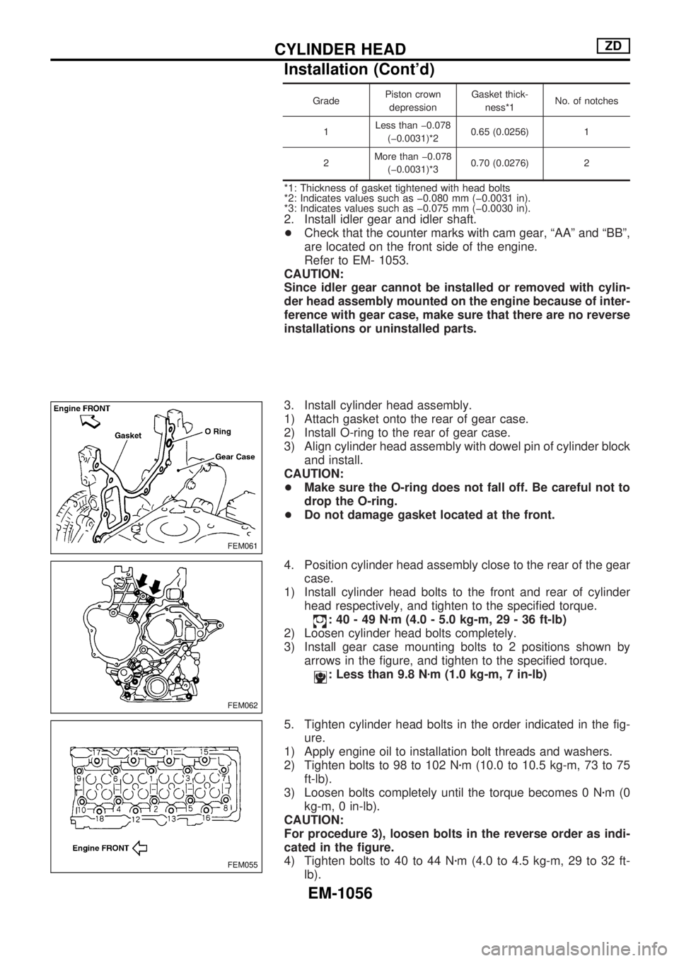
GradePiston crown
depressionGasket thick-
ness*1No. of notches
1Less than þ0.078
(þ0.0031)*20.65 (0.0256) 1
2More than þ0.078
(þ0.0031)*30.70 (0.0276) 2
*1: Thickness of gasket tightened with head bolts
*2: Indicates values such as þ0.080 mm (þ0.0031 in).
*3: Indicates values such as þ0.075 mm (þ0.0030 in).
2. Install idler gear and idler shaft.
+Check that the counter marks with cam gear, ªAAº and ªBBº,
are located on the front side of the engine.
Refer to EM- 1053.
CAUTION:
Since idler gear cannot be installed or removed with cylin-
der head assembly mounted on the engine because of inter-
ference with gear case, make sure that there are no reverse
installations or uninstalled parts.
3. Install cylinder head assembly.
1) Attach gasket onto the rear of gear case.
2) Install O-ring to the rear of gear case.
3) Align cylinder head assembly with dowel pin of cylinder block
and install.
CAUTION:
+Make sure the O-ring does not fall off. Be careful not to
drop the O-ring.
+Do not damage gasket located at the front.
4. Position cylinder head assembly close to the rear of the gear
case.
1) Install cylinder head bolts to the front and rear of cylinder
head respectively, and tighten to the specified torque.
:40-49Nzm (4.0 - 5.0 kg-m, 29 - 36 ft-lb)
2) Loosen cylinder head bolts completely.
3) Install gear case mounting bolts to 2 positions shown by
arrows in the figure, and tighten to the specified torque.
: Less than 9.8 Nzm (1.0 kg-m, 7 in-lb)
5. Tighten cylinder head bolts in the order indicated in the fig-
ure.
1) Apply engine oil to installation bolt threads and washers.
2) Tighten bolts to 98 to 102 Nzm (10.0 to 10.5 kg-m, 73 to 75
ft-lb).
3) Loosen bolts completely until the torque becomes 0 Nzm(0
kg-m, 0 in-lb).
CAUTION:
For procedure 3), loosen bolts in the reverse order as indi-
cated in the figure.
4) Tighten bolts to 40 to 44 Nzm (4.0 to 4.5 kg-m, 29 to 32 ft-
lb).
FEM061
FEM062
FEM055
CYLINDER HEADZD
Installation (Cont'd)
EM-1056
Page 795 of 1033
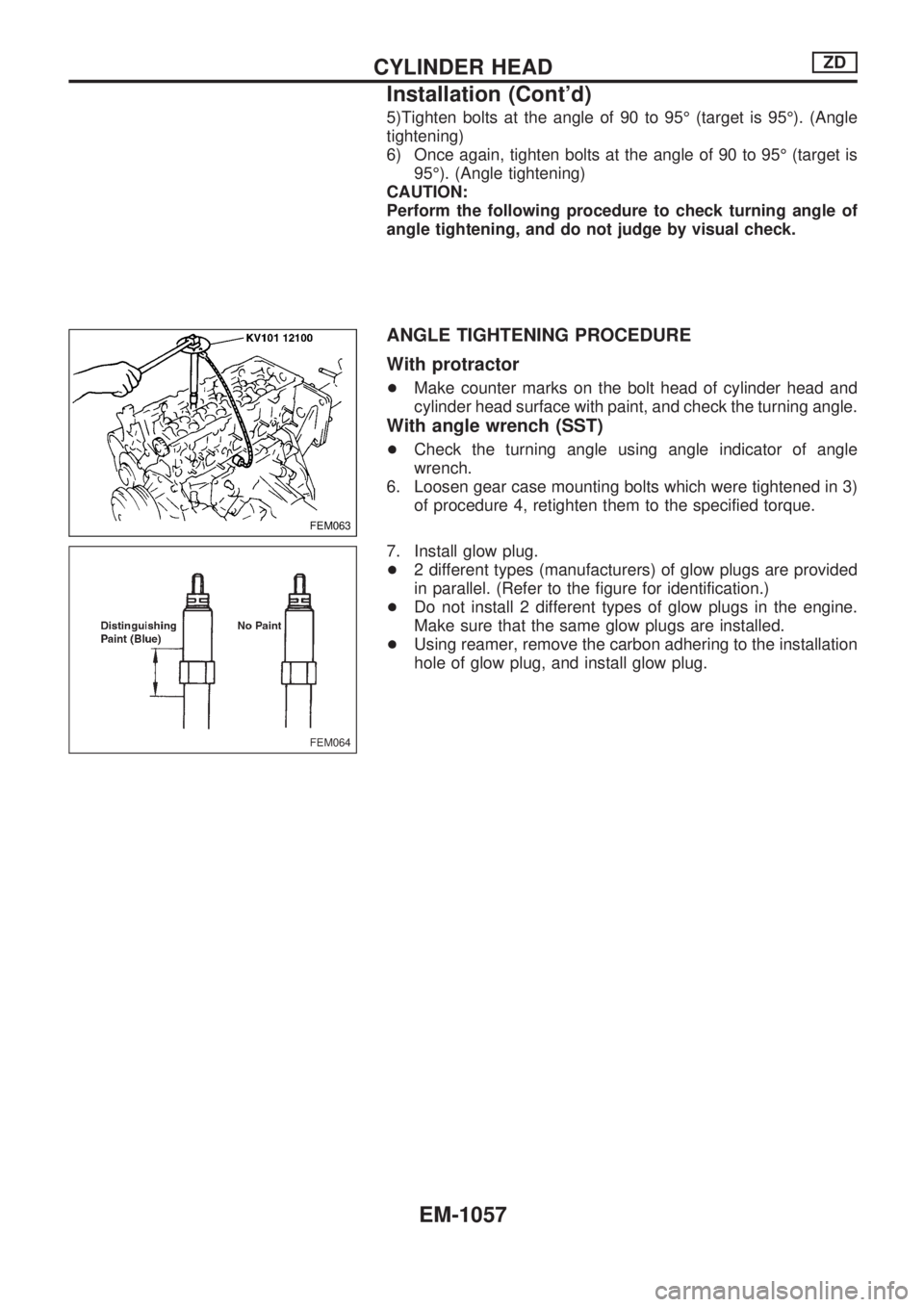
5)Tighten bolts at the angle of 90 to 95É (target is 95É). (Angle
tightening)
6) Once again, tighten bolts at the angle of 90 to 95É (target is
95É). (Angle tightening)
CAUTION:
Perform the following procedure to check turning angle of
angle tightening, and do not judge by visual check.
ANGLE TIGHTENING PROCEDURE
With protractor
+Make counter marks on the bolt head of cylinder head and
cylinder head surface with paint, and check the turning angle.
With angle wrench (SST)
+Check the turning angle using angle indicator of angle
wrench.
6. Loosen gear case mounting bolts which were tightened in 3)
of procedure 4, retighten them to the specified torque.
7. Install glow plug.
+2 different types (manufacturers) of glow plugs are provided
in parallel. (Refer to the figure for identification.)
+Do not install 2 different types of glow plugs in the engine.
Make sure that the same glow plugs are installed.
+Using reamer, remove the carbon adhering to the installation
hole of glow plug, and install glow plug.
FEM063
FEM064
CYLINDER HEADZD
Installation (Cont'd)
EM-1057
Page 800 of 1033
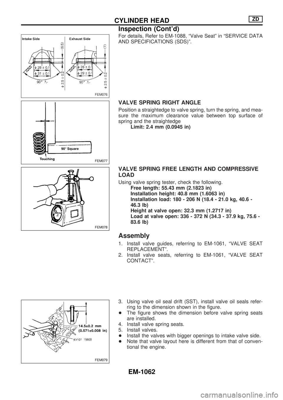
For details, Refer to EM-1088, ªValve Seatº in ªSERVICE DATA
AND SPECIFICATIONS (SDS)º.
VALVE SPRING RIGHT ANGLE
Position a straightedge to valve spring, turn the spring, and mea-
sure the maximum clearance value between top surface of
spring and the straightedge
Limit: 2.4 mm (0.0945 in)
VALVE SPRING FREE LENGTH AND COMPRESSIVE
LOAD
Using valve spring tester, check the following.
Free length: 55.43 mm (2.1823 in)
Installation height: 40.8 mm (1.6063 in)
Installation load: 180 - 206 N (18.4 - 21.0 kg, 40.6 -
46.3 lb)
Height at valve open: 32.3 mm (1.2717 in)
Load at valve open: 336 - 372 N (34.3 - 37.9 kg, 75.6 -
83.6 lb)
Assembly
1. Install valve guides, referring to EM-1061, ªVALVE SEAT
REPLACEMENTº.
2. Install valve seats, referring to EM-1061, ªVALVE SEAT
CONTACTº.
3. Using valve oil seal drift (SST), install valve oil seals refer-
ring to the dimension shown in the figure.
+The figure shows the dimension before valve spring seats
are installed.
4. Install valve spring seats.
5. Install valves.
+Install the valves with bigger openings to intake valve side.
+Note that valve layout here is different from that of conven-
tional the engine.
FEM076
FEM077
FEM078
FEM079
CYLINDER HEADZD
Inspection (Cont'd)
EM-1062
Page 804 of 1033
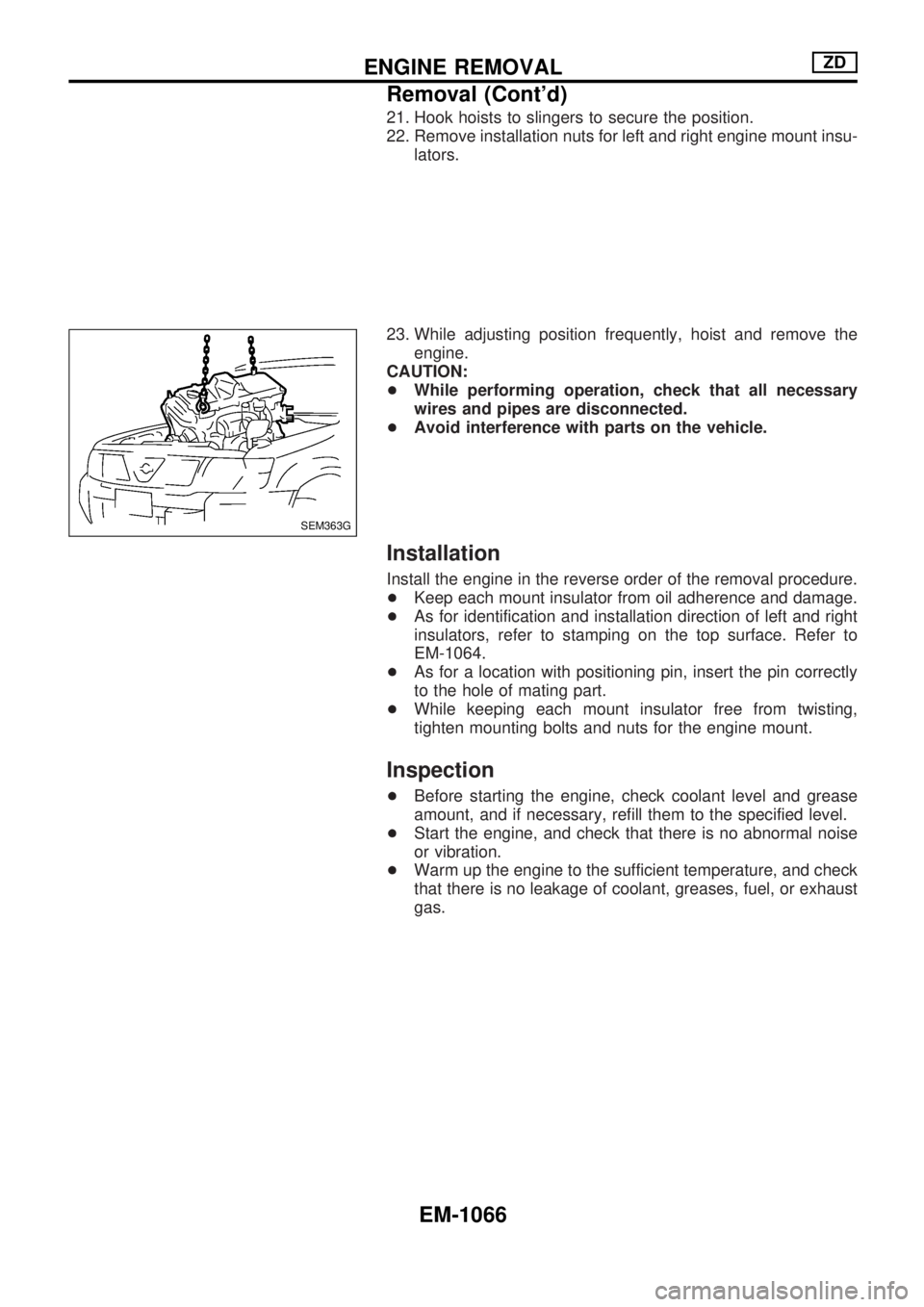
21. Hook hoists to slingers to secure the position.
22. Remove installation nuts for left and right engine mount insu-
lators.
23. While adjusting position frequently, hoist and remove the
engine.
CAUTION:
+While performing operation, check that all necessary
wires and pipes are disconnected.
+Avoid interference with parts on the vehicle.
Installation
Install the engine in the reverse order of the removal procedure.
+Keep each mount insulator from oil adherence and damage.
+As for identification and installation direction of left and right
insulators, refer to stamping on the top surface. Refer to
EM-1064.
+As for a location with positioning pin, insert the pin correctly
to the hole of mating part.
+While keeping each mount insulator free from twisting,
tighten mounting bolts and nuts for the engine mount.
Inspection
+Before starting the engine, check coolant level and grease
amount, and if necessary, refill them to the specified level.
+Start the engine, and check that there is no abnormal noise
or vibration.
+Warm up the engine to the sufficient temperature, and check
that there is no leakage of coolant, greases, fuel, or exhaust
gas.
SEM363G
ENGINE REMOVALZD
Removal (Cont'd)
EM-1066
Page 809 of 1033
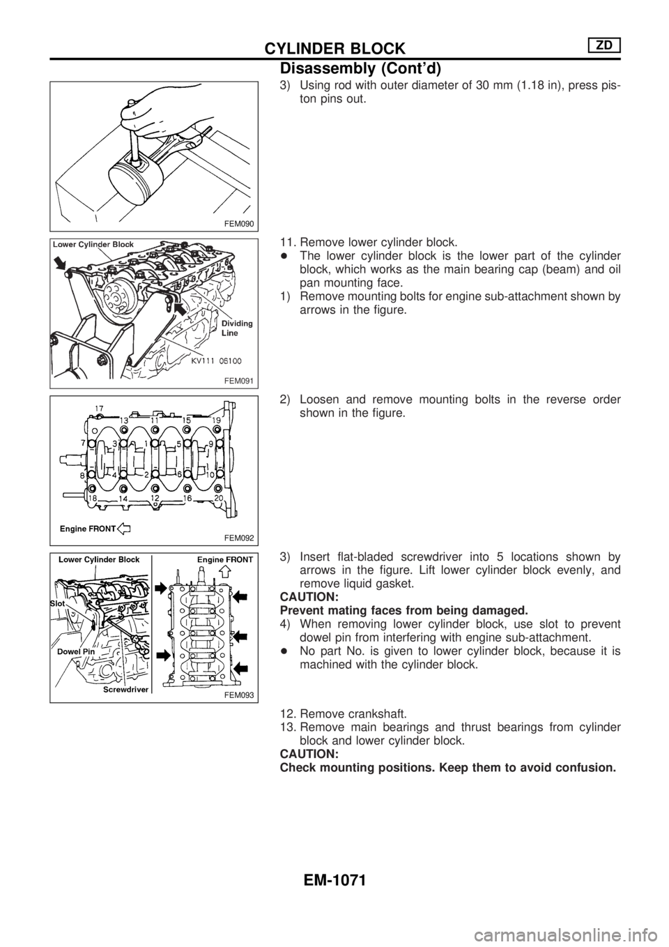
3) Using rod with outer diameter of 30 mm (1.18 in), press pis-
ton pins out.
11. Remove lower cylinder block.
+The lower cylinder block is the lower part of the cylinder
block, which works as the main bearing cap (beam) and oil
pan mounting face.
1) Remove mounting bolts for engine sub-attachment shown by
arrows in the figure.
2) Loosen and remove mounting bolts in the reverse order
shown in the figure.
3) Insert flat-bladed screwdriver into 5 locations shown by
arrows in the figure. Lift lower cylinder block evenly, and
remove liquid gasket.
CAUTION:
Prevent mating faces from being damaged.
4) When removing lower cylinder block, use slot to prevent
dowel pin from interfering with engine sub-attachment.
+No part No. is given to lower cylinder block, because it is
machined with the cylinder block.
12. Remove crankshaft.
13. Remove main bearings and thrust bearings from cylinder
block and lower cylinder block.
CAUTION:
Check mounting positions. Keep them to avoid confusion.
FEM090
FEM091
FEM092
FEM093
CYLINDER BLOCKZD
Disassembly (Cont'd)
EM-1071
Page 813 of 1033
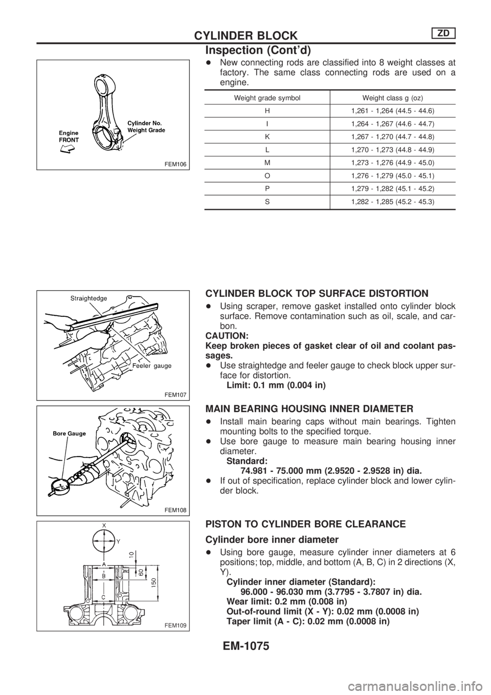
+New connecting rods are classified into 8 weight classes at
factory. The same class connecting rods are used on a
engine.
Weight grade symbol Weight class g (oz)
H 1,261 - 1,264 (44.5 - 44.6)
I 1,264 - 1,267 (44.6 - 44.7)
K 1,267 - 1,270 (44.7 - 44.8)
L 1,270 - 1,273 (44.8 - 44.9)
M 1,273 - 1,276 (44.9 - 45.0)
O 1,276 - 1,279 (45.0 - 45.1)
P 1,279 - 1,282 (45.1 - 45.2)
S 1,282 - 1,285 (45.2 - 45.3)
CYLINDER BLOCK TOP SURFACE DISTORTION
+Using scraper, remove gasket installed onto cylinder block
surface. Remove contamination such as oil, scale, and car-
bon.
CAUTION:
Keep broken pieces of gasket clear of oil and coolant pas-
sages.
+Use straightedge and feeler gauge to check block upper sur-
face for distortion.
Limit: 0.1 mm (0.004 in)
MAIN BEARING HOUSING INNER DIAMETER
+Install main bearing caps without main bearings. Tighten
mounting bolts to the specified torque.
+Use bore gauge to measure main bearing housing inner
diameter.
Standard:
74.981 - 75.000 mm (2.9520 - 2.9528 in) dia.
+If out of specification, replace cylinder block and lower cylin-
der block.
PISTON TO CYLINDER BORE CLEARANCE
Cylinder bore inner diameter
+Using bore gauge, measure cylinder inner diameters at 6
positions; top, middle, and bottom (A, B, C) in 2 directions (X,
Y).
Cylinder inner diameter (Standard):
96.000 - 96.030 mm (3.7795 - 3.7807 in) dia.
Wear limit: 0.2 mm (0.008 in)
Out-of-round limit (X - Y): 0.02 mm (0.0008 in)
Taper limit (A - C): 0.02 mm (0.0008 in)
FEM106
FEM107
FEM108
FEM109
CYLINDER BLOCKZD
Inspection (Cont'd)
EM-1075