Page 482 of 1033
Diagnostic Procedure
1 INSPECTION START
Do you have CONSULT-II?
Yes or No
YescGO TO 2.
NocGO TO 3.
2 CHECK OVERALL FUNCTION
With CONSULT-II
1. Start engine and let it idle.
2. Select ªSWIRL CONT S/V 1º in ªACTIVE TESTº mode with CONSULT-II.
3. Touch ªONº and ªOFFº alternately on CONSULT-II screen.
4. Make sure that swirl control valve actuator rod moves according to ªSWIRL CONT S/V 1º indication.
SEF307Z
OK or NG
OKcINSPECTION END
NGcGO TO 4.
3 CHECK OVERALL FUNCTION
Without CONSULT-II
1. Lift up the vehicle.
2. Start engine and warm it up to normal operating temperature.
3. Run engine at idle speed.
4. Make sure that swirl control valve actuator rod moves when shifting the shift lever to ªPº or ªNeutralº position and then to posi-
tions other than ªPº and ªNeutralº.
SEF308Z
OK or NG
OKcINSPECTION END
NGcGO TO 5.
SWIRL CONTROL VALVE CONTROL
SOLENOID VALVEZD30DDTi
EC-1249
Page 483 of 1033
4 CHECK VACUUM SOURCE
With CONSULT-II
1. Turn ignition switch ªOFFº.
2. Disconnect vacuum hose connected to swirl control valve actuator.
3. Start engine and let it idle.
4. Select ªSWIRL CONT S/V 1º in ªACTIVE TESTº mode with CONSULT-II.
5. Touch ªONº and ªOFFº alternately on CONSULT-II screen.
6. Check vacuum hose for vacuum existence under the following conditions.
SEF309Z
OK or NG
OKcGO TO 7.
NGcGO TO 6.
5 CHECK VACUUM SOURCE
Without CONSULT-II
1. Turn ignition switch ªOFFº.
2. Disconnect vacuum hose connected to swirl control valve actuator.
3. Lift up the vehicle.
4. Start engine and warm it up to normal operating temperature.
5. Run engine at idle speed
6. Check vacuum hose for vacuum existence under the following conditions.
SEF310Z
OK or NG
OKcGO TO 7.
NGcGO TO 6.
SWIRL CONTROL VALVE CONTROL
SOLENOID VALVEZD30DDTi
Diagnostic Procedure (Cont'd)
EC-1250
SWIRL CONT S/V 1 Vacuum
Should exist
Should not exist
Page 489 of 1033
Diagnostic Procedure
1 CHECK OVERALL FUNCTION
1. Start engine and let it idle.
2. Make sure that intake air control valve actuator rod moves when turning ignition switch ªOFFº.
SEF315Z
OK or NG
OKcINSPECTION END
NGcGO TO 2.
2 CHECK VACUUM SOURCE
1. Turn ignition switch ªOFFº.
2. Disconnect vacuum hose connected to intake air control valve actuator.
3. Start engine and let it idle.
4. Check vacuum hose for vacuum existence under the following conditions.
SEF316Z
OK or NG
OKcGO TO 3.
NGcGO TO 4.
INTAKE AIR CONTROL VALVE CONTROL
SOLENOID VALVEZD30DDTi
EC-1256
Page 497 of 1033
Diagnostic Procedure
1 CHECK OVERALL FUNCTION
1. Start engine and let it idle.
2. Make sure that variable nozzle turbocharger control actuator rod moves when revving engine up to 3,000 rpm and returning to
idle.
SEF320Z
OK or NG
OKcINSPECTION END
NGcGO TO 2.
2 CHECK VACUUM SOURCE
1. Turn ignition switch ªOFFº.
2. Disconnect vacuum hose connected to variable nozzle turbocharger control actuator.
3. Start engine and let it idle.
4. Check vacuum hose for vacuum existence.
SEF321Z
OK or NG
OKcGO TO 3.
NGcGO TO 5.
VARIABLE NOZZLE TURBOCHARGER CONTROL
SOLENOID VALVEZD30DDTi
EC-1264
Page 504 of 1033
Diagnostic Procedure
1 INSPECTION START
Do you have CONSULT-II?
Yes or No
YescGO TO 2.
NocGO TO 3.
2 CHECK OVERALL FUNCTION-I
With CONSULT-II
1. Turn ignition switch ªONº.
2. Select ªCOOLAN TEMP/Sº in ªDATA MONITORº mode with CONSULT-II.
3. Make sure that ªCOOLAN TEMP/Sº indication is below 60ÉC (140ÉF). If out of range, cool down the engine.
NOTE:
The following procedure should be performed before the engine coolant temperature reaches 87ÉC (189ÉF).
4. Disconnect vacuum hose connected to exhaust gas control valve actuator.
5. Start engine and let it idle.
6. Check vacuum hose for vacuum existence under the following conditions.
SEF318Z
OK or NG
OKcGO TO 4.
NGcGO TO 5.
EXHAUST GAS CONTROL VALVE CONTROL
SOLENOID VALVEZD30DDTi
EC-1271
Page 505 of 1033

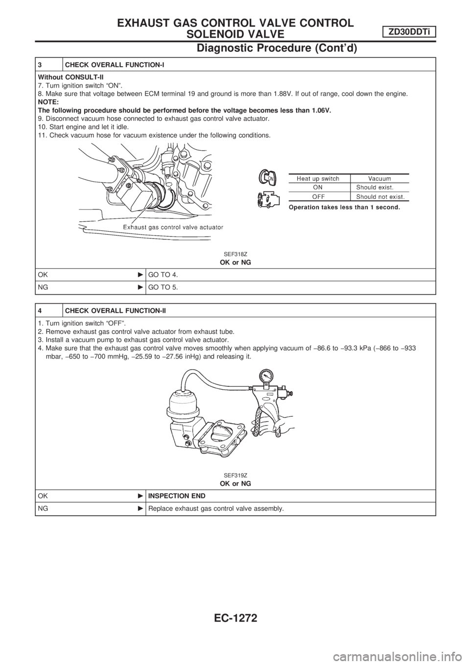
3 CHECK OVERALL FUNCTION-I
Without CONSULT-II
7. Turn ignition switch ªONº.
8. Make sure that voltage between ECM terminal 19 and ground is more than 1.88V. If out of range, cool down the engine.
NOTE:
The following procedure should be performed before the voltage becomes less than 1.06V.
9. Disconnect vacuum hose connected to exhaust gas control valve actuator.
10. Start engine and let it idle.
11. Check vacuum hose for vacuum existence under the following conditions.
SEF318Z
OK or NG
OKcGO TO 4.
NGcGO TO 5.
4 CHECK OVERALL FUNCTION-II
1. Turn ignition switch ªOFFº.
2. Remove exhaust gas control valve actuator from exhaust tube.
3. Install a vacuum pump to exhaust gas control valve actuator.
4. Make sure that the exhaust gas control valve moves smoothly when applying vacuum of þ86.6 to þ93.3 kPa (þ866 to þ933
mbar, þ650 to þ700 mmHg, þ25.59 to þ27.56 inHg) and releasing it.
SEF319Z
OK or NG
OKcINSPECTION END
NGcReplace exhaust gas control valve assembly.
EXHAUST GAS CONTROL VALVE CONTROL
SOLENOID VALVEZD30DDTi
Diagnostic Procedure (Cont'd)
EC-1272
Page 511 of 1033

ELECTRICAL SYSTEM
SECTION
EL
When you read wiring diagrams:
+Read GI section, ªHOW TO READ WIRING DIAGRAMSº.
When you perform trouble diagnoses, read GI section, ªHOW TO FOLLOW FLOW
CHART IN TROUBLE DIAGNOSESº and ªHOW TO PERFORM EFFICIENT DIAGNOSIS
FOR AN ELECTRICAL INCIDENTº.
+Check for any service bulletins before servicing the vehicle.
MODIFICATION NOTICE:
+Power window (driver's side only) with an interruption detection function has been adopted.
+ID code entry procedure of multi-remote control system has been changed.
+NATS (Nissan Anti-Theft System) has been adopted on ZD engine model.
CONTENTS
PRECAUTIONS AND PREPARATION............... 1003
Supplemental Restraint System (SRS) ªAIR
BAGº and ªSEAT BELT PRE-TENSIONERº ... 1003
POWER SUPPLY ROUTING............................... 1004
Schematic ........................................................ 1004
Wiring Diagram Ð POWER Ð ........................ 1005
GROUND DISTRIBUTION/LHD MODELS.......... 1013
Engine Room Harness..................................... 1013
Engine Control Harness................................... 1016
Main Harness ................................................... 1017
Body Harness .................................................. 1020
Body No. 2 Harness ........................................ 1022
Back Door and Rear Window Defogger
Harness ............................................................ 1023
GROUND DISTRIBUTION/RHD MODELS......... 1024
Engine Room Harness..................................... 1024
Engine Control Harness................................... 1027
Main Harness ................................................... 1028
Body Harness .................................................. 1031
Body No. 2 Harness ........................................ 1033
Back Door and Rear Window Defogger
Harness ............................................................ 1034
BATTERY............................................................. 1035
Service Data and Specifications (SDS) ........... 1035
STARTING SYSTEM........................................... 1036
Wiring Diagram Ð START Ð/M/T Models...... 1036
Wiring Diagram Ð START Ð/A/T Models ...... 1037
Construction ..................................................... 1038Service Data and Specifications (SDS) ........... 1039
CHARGING SYSTEM.......................................... 1040
Wiring Diagram Ð CHARGE ........................... 1040
Construction ..................................................... 1041
Service Data and Specifications (SDS) ........... 1041
COMBINATION SWITCH.................................... 1042
Check ............................................................... 1042
STEERING SWITCH............................................ 1043
Check ............................................................... 1043
HEADLAMP Ð Daytime Light System Ð........ 1044
Wiring Diagram Ð DTRL Ð ............................ 1044
PARKING, LICENSE AND TAIL LAMPS........... 1046
Wiring Diagram Ð TAIL/L Ð/LHD Models ...... 1046
Wiring Diagram Ð TAIL/L Ð/RHD Models ..... 1048
STOP LAMP........................................................ 1050
Wiring Diagram Ð STOP/L Ð......................... 1050
BACK-UP LAMP.................................................. 1051
Wiring Diagram Ð BACK/L Ð/RHD Models ... 1051
FRONT FOG LAMP............................................. 1052
Wiring Diagram Ð F/FOG Ð .......................... 1052
REAR FOG LAMP............................................... 1053
Wiring Diagram Ð R/FOG Ð .......................... 1053
CORNERING LAMP............................................ 1054
Wiring Diagram Ð CORNER Ð/LHD Models . 1054
System Description/RHD Models .................... 1055
Wiring Diagram Ð CORNER Ð/RHD Models1056
Trouble Diagnoses/RHD Models ..................... 1057
EL
Page 657 of 1033
DIAGNOSTIC PROCEDURE 7
(NATS release signal check)
Does engine start properly?
Yes
cNo
Check NATS system.
CHECK NATS SIGNAL CIRCUIT.
1. Disconnect super lock control unit con-
nector and NATS IMMU connector.
2. Check continuity between super lock
control unit terminal
V34and NATS
IMMU terminal
V3.
Continuity should exist.
3. Check continuity between super lock
control unit terminal
V34and ground.
Continuity should not exist.
Refer to wiring diagram in EL-1128
(LHD), EL-1133 (RHD).
OK
cNG
Repair harness.
CHECK NATS RELEASE SIGNAL.
1. Connect super lock control unit con-
nector and NATS IMMU connector.
2. Check voltage between super lock con-
trol unit terminal
V34and ground.
OK
cNG
Check NATS system.
Replace super lock control unit.
Ignition switch conditionVoltage
[V]
OFF
5
More than 20 seconds after ignition
switch turned ON
For 20 seconds after ignition switch
turned ONPulse
SEL142X
SEL143X
.
.
.
POWER DOOR LOCK Ð Super Lock Ð
Trouble Diagnoses (Cont'd)
EL-1147