Page 819 of 1033
Assembly
1. Blow air sufficiently to inside coolant passage, oil passage,
crankcase, and cylinder bore to remove foreign matter.
2. Install main bearings and thrust bearings.
1) Remove contamination, dust and oil from bearing mounting
positions on cylinder block and main bearing caps.
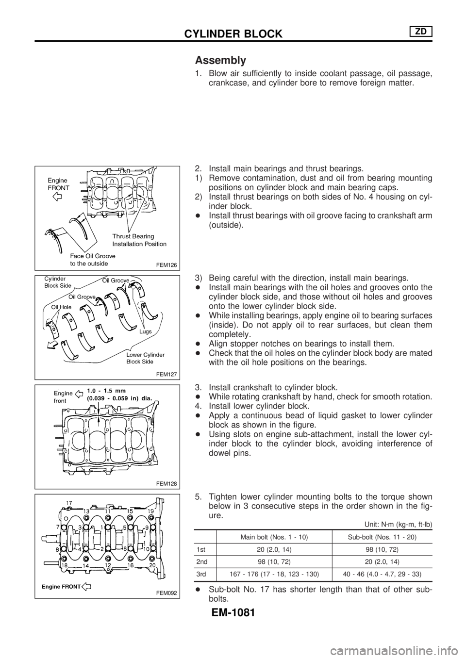
2) Install thrust bearings on both sides of No. 4 housing on cyl-
inder block.
+Install thrust bearings with oil groove facing to crankshaft arm
(outside).
3) Being careful with the direction, install main bearings.
+Install main bearings with the oil holes and grooves onto the
cylinder block side, and those without oil holes and grooves
onto the lower cylinder block side.
+While installing bearings, apply engine oil to bearing surfaces
(inside). Do not apply oil to rear surfaces, but clean them
completely.
+Align stopper notches on bearings to install them.
+Check that the oil holes on the cylinder block body are mated
with the oil hole positions on the bearings.
3. Install crankshaft to cylinder block.
+While rotating crankshaft by hand, check for smooth rotation.
4. Install lower cylinder block.
+Apply a continuous bead of liquid gasket to lower cylinder
block as shown in the figure.
+Using slots on engine sub-attachment, install the lower cyl-
inder block to the cylinder block, avoiding interference of
dowel pins.
5. Tighten lower cylinder mounting bolts to the torque shown
below in 3 consecutive steps in the order shown in the fig-
ure.
Unit: Nzm (kg-m, ft-lb)
Main bolt (Nos. 1 - 10) Sub-bolt (Nos. 11 - 20)
1st 20 (2.0, 14) 98 (10, 72)
2nd 98 (10, 72) 20 (2.0, 14)
3rd 167 - 176 (17 - 18, 123 - 130) 40 - 46 (4.0 - 4.7, 29 - 33)
+Sub-bolt No. 17 has shorter length than that of other sub-
bolts.
FEM126
FEM127
FEM128
FEM092
CYLINDER BLOCKZD
EM-1081
Page 820 of 1033
6. Install mounting bolts for engine sub-attachment shown by
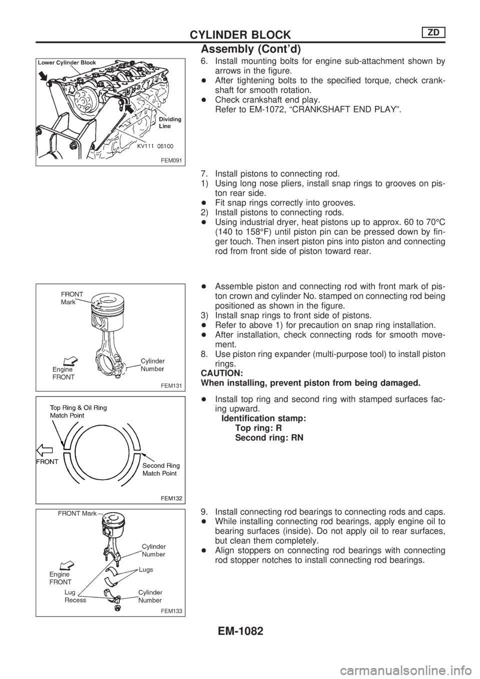
arrows in the figure.
+After tightening bolts to the specified torque, check crank-
shaft for smooth rotation.
+Check crankshaft end play.
Refer to EM-1072, ªCRANKSHAFT END PLAYº.
7. Install pistons to connecting rod.
1) Using long nose pliers, install snap rings to grooves on pis-
ton rear side.
+Fit snap rings correctly into grooves.
2) Install pistons to connecting rods.
+Using industrial dryer, heat pistons up to approx. 60 to 70ÉC
(140 to 158ÉF) until piston pin can be pressed down by fin-
ger touch. Then insert piston pins into piston and connecting
rod from front side of piston toward rear.
+Assemble piston and connecting rod with front mark of pis-
ton crown and cylinder No. stamped on connecting rod being
positioned as shown in the figure.
3) Install snap rings to front side of pistons.
+Refer to above 1) for precaution on snap ring installation.
+After installation, check connecting rods for smooth move-
ment.
8. Use piston ring expander (multi-purpose tool) to install piston
rings.
CAUTION:
When installing, prevent piston from being damaged.
+Install top ring and second ring with stamped surfaces fac-
ing upward.
Identification stamp:
Top ring: R
Second ring: RN
9. Install connecting rod bearings to connecting rods and caps.
+While installing connecting rod bearings, apply engine oil to
bearing surfaces (inside). Do not apply oil to rear surfaces,
but clean them completely.
+Align stoppers on connecting rod bearings with connecting
rod stopper notches to install connecting rod bearings.
FEM091
FEM131
FEM132
FEM133
CYLINDER BLOCKZD
Assembly (Cont'd)
EM-1082
Page 821 of 1033
10. Install piston and connecting rod assembly to crankshaft.
+Move crankshaft pin to be removed to BDC.
+Align cylinder position with cylinder No. on connecting rod to
install piston and connecting rod assembly.
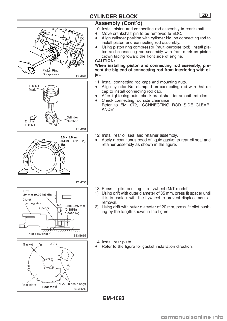
+Using piston ring compressor (multi-purpose tool), install pis-
ton and connecting rod assembly with front mark on piston
crown facing toward the front side of engine.
CAUTION:
When installing piston and connecting rod assembly, pre-
vent the big end of connecting rod from interfering with oil
jet.
11. Install connecting rod caps and mounting nuts.
+Align cylinder No. stamped on connecting rod with that on
cap to install connecting rod cap.
+After tightening nuts, check crankshaft for smooth rotation.
+Check connecting rod side clearance.
Refer to EM-1072, ªCONNECTING ROD SIDE CLEAR-
ANCEº.
12. Install rear oil seal and retainer assembly.
+Apply a continuous bead of liquid gasket to rear oil seal and
retainer assembly as shown in the figure.
13. Press fit pilot bushing into flywheel (M/T model).
1) Using drift with outer diameter of 35 mm, press fit spacer until
it is in contact with the flywheel to prevent displacement at
removal.
2) Using drift with outer diameter of 20 mm, press fit pilot bush-
ing by the length shown in the figure.
14. Install rear plate.
+Refer to the figure for gasket installation direction.
FEM134
FEM131
FEM053
SEM366G
SEM367G
CYLINDER BLOCKZD
Assembly (Cont'd)
EM-1083
Page 846 of 1033
GENERAL INFORMATION
SECTION
GI
OUTLINE OF MODIFICATIONS:
+Side air bag has been adopted.
+Power window (driver's side only) with an interruption detection function has been adopted.
+ZD30DDTi engine has been adopted in place of RD28ETi engine.
+CONSULT-II has been adopted.
+ID code entry procedure of multi-remote control system has been changed.
APPLIED FROM:
For Europe:
JN1TESY61U0000001
JN1KESY61U0000001
For Israel:
JN1TESY611X800001
JN1KESY611X800001
CONTENTS
PRECAUTIONS AND PREPARATION............... 1002
Supplemental Restraint System (SRS) ªAIR
BAGº and ªSEAT BELT PRE-TENSIONERº ... 1002
Precautions for Fuel......................................... 1002
CONSULT-II CHECKING SYSTEM..................... 1003
Function and System Application .................... 1003
Nickel Metal Hydride Battery Replacement ..... 1003
Checking Equipment ........................................ 1004CONSULT-II Data Link Connector (DLC)
Circuit ............................................................... 1004
IDENTIFICATION INFORMATION...................... 1005
Model Variation ................................................ 1005
Identification Number ....................................... 1007
LIFTING POINTS AND TOW TRUCK TOWING. 1009
Screw Jack....................................................... 1009
Tow Truck Towing ........................................... 1010
GI
Page 848 of 1033
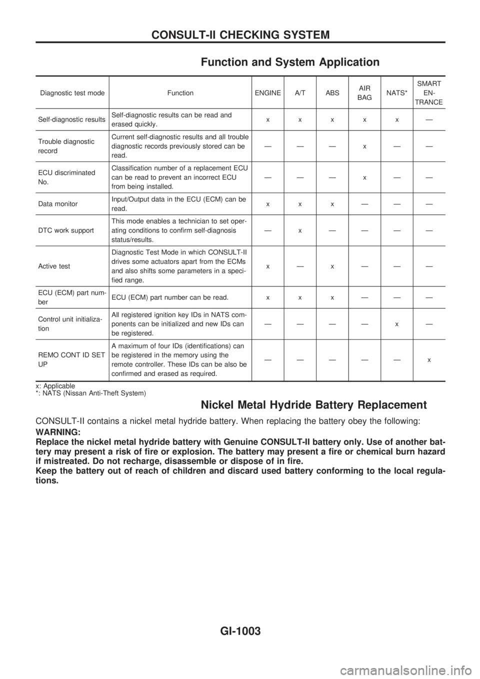
Function and System Application
Diagnostic test mode Function ENGINE A/T ABSAIR
BAGNATS*SMART
EN-
TRANCE
Self-diagnostic resultsSelf-diagnostic results can be read and
erased quickly.xxxxxÐ
Trouble diagnostic
recordCurrent self-diagnostic results and all trouble
diagnostic records previously stored can be
read.ÐÐÐxÐÐ
ECU discriminated
No.Classification number of a replacement ECU
can be read to prevent an incorrect ECU
from being installed.ÐÐÐxÐÐ
Data monitorInput/Output data in the ECU (ECM) can be
read.xxxÐÐÐ
DTC work supportThis mode enables a technician to set oper-
ating conditions to confirm self-diagnosis
status/results.Ð x ÐÐÐÐ
Active testDiagnostic Test Mode in which CONSULT-II
drives some actuators apart from the ECMs
and also shifts some parameters in a speci-
fied range.xÐxÐÐÐ
ECU (ECM) part num-
berECU (ECM) part number can be read. x x x Ð Ð Ð
Control unit initializa-
tionAll registered ignition key IDs in NATS com-
ponents can be initialized and new IDs can
be registered.ÐÐÐÐ x Ð
REMO CONT ID SET
UPA maximum of four IDs (identifications) can
be registered in the memory using the
remote controller. These IDs can be also be
confirmed and erased as required.ÐÐÐÐÐ x
x: Applicable
*: NATS (Nissan Anti-Theft System)
Nickel Metal Hydride Battery Replacement
CONSULT-II contains a nickel metal hydride battery. When replacing the battery obey the following:
WARNING:
Replace the nickel metal hydride battery with Genuine CONSULT-II battery only. Use of another bat-
tery may present a risk of fire or explosion. The battery may present a fire or chemical burn hazard
if mistreated. Do not recharge, disassemble or dispose of in fire.
Keep the battery out of reach of children and discard used battery conforming to the local regula-
tions.
CONSULT-II CHECKING SYSTEM
GI-1003
Page 884 of 1033
ENGINE LUBRICATION &
COOLING SYSTEMS
SECTION
LC
MODIFICATION NOTICE:
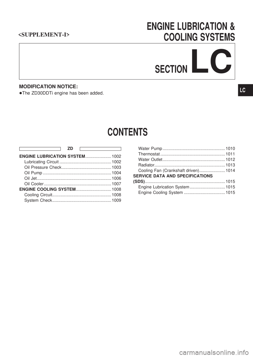
+The ZD30DDTi engine has been added.
CONTENTS
ZD
ENGINE LUBRICATION SYSTEM...................... 1002
Lubricating Circuit ............................................ 1002
Oil Pressure Check .......................................... 1003
Oil Pump .......................................................... 1004
Oil Jet ............................................................... 1006
Oil Cooler ......................................................... 1007
ENGINE COOLING SYSTEM.............................. 1008
Cooling Circuit.................................................. 1008
System Check .................................................. 1009Water Pump ..................................................... 1010
Thermostat ....................................................... 1011
Water Outlet ..................................................... 1012
Radiator............................................................ 1013
Cooling Fan (Crankshaft driven)...................... 1014
SERVICE DATA AND SPECIFICATIONS
(SDS).................................................................... 1015
Engine Lubrication System .............................. 1015
Engine Cooling System ................................... 1015
LC
Page 886 of 1033
Oil Pressure Check
WARNING:
+Be careful not to burn yourself, as the engine and oil
may be hot.
+Oil pressure check should be done in ªNeutralº gear
position.
1. Check oil level.
2. Remove oil pressure switch.
3. Install pressure gauge.
4. Start engine and warm it up to normal operating temperature.
5. Check oil pressure with engine running under no-load.
Engine speed
rpmApproximate discharge pressure
kPa (bar, kg/cm2, psi)
Idle speed
2,000
4,000More than 147 (1.47, 1.5, 21)
More than 539 (5.39, 5.5, 78)
More than 736 (7.36, 7.5, 107)
If difference is extreme, check oil passage and oil pump.
6. Install oil pressure switch with sealant.
Oil pressure switch:
:13-17Nzm (1.25 - 1.75 kg-m,9-12ft-lb)
SLC694A
JLC362B
ENGINE LUBRICATION SYSTEMZD
LC-1003
Page 888 of 1033
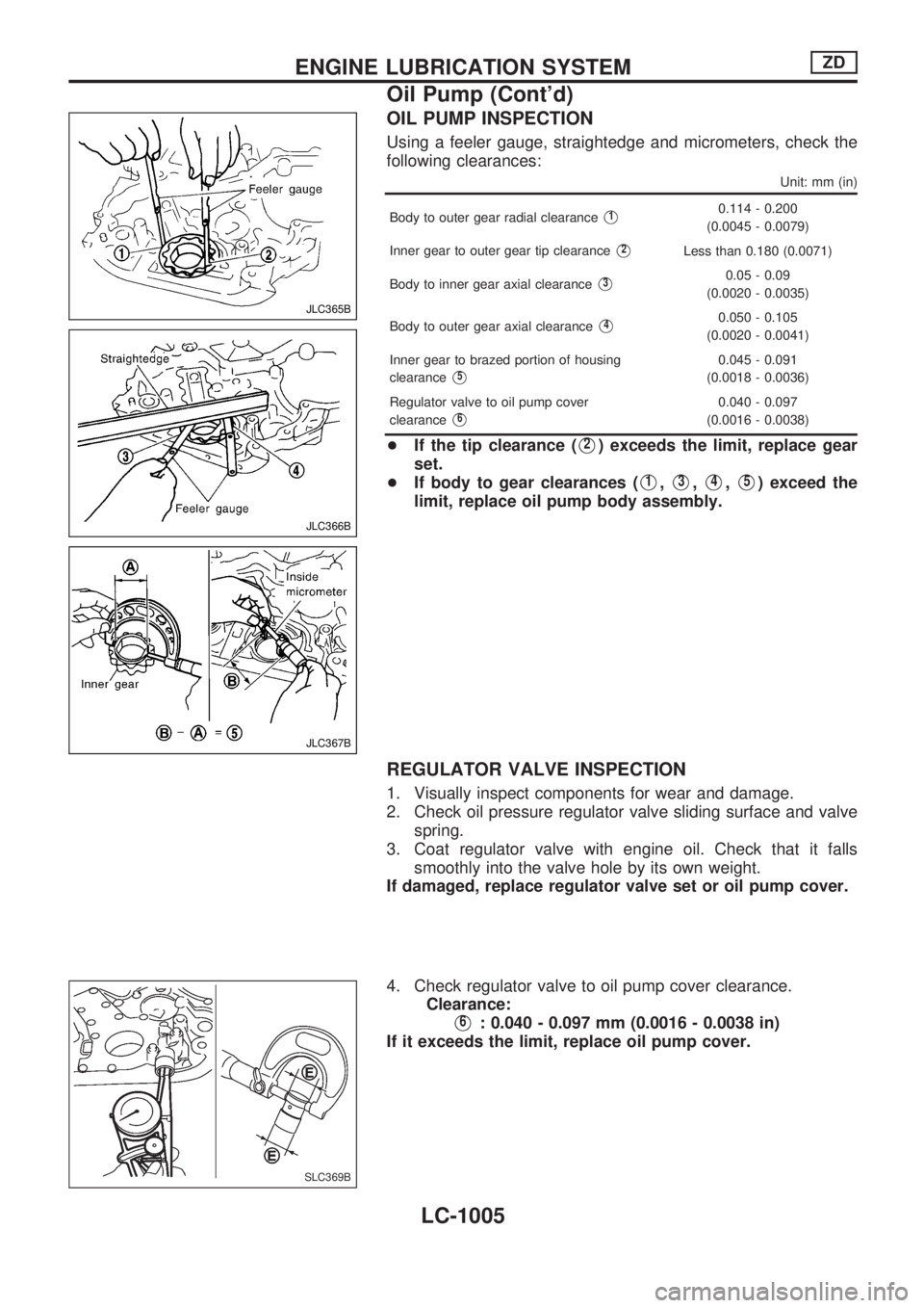
OIL PUMP INSPECTION
Using a feeler gauge, straightedge and micrometers, check the
following clearances:
Unit: mm (in)
Body to outer gear radial clearanceV10.114 - 0.200
(0.0045 - 0.0079)
Inner gear to outer gear tip clearance
V2Less than 0.180 (0.0071)
Body to inner gear axial clearance
V30.05 - 0.09
(0.0020 - 0.0035)
Body to outer gear axial clearance
V40.050 - 0.105
(0.0020 - 0.0041)
Inner gear to brazed portion of housing
clearance
V50.045 - 0.091
(0.0018 - 0.0036)
Regulator valve to oil pump cover
clearance
V60.040 - 0.097
(0.0016 - 0.0038)
+If the tip clearance (V2) exceeds the limit, replace gear
set.
+If body to gear clearances (
V1,V3,V4,V5) exceed the
limit, replace oil pump body assembly.
REGULATOR VALVE INSPECTION
1. Visually inspect components for wear and damage.
2. Check oil pressure regulator valve sliding surface and valve
spring.
3. Coat regulator valve with engine oil. Check that it falls
smoothly into the valve hole by its own weight.
If damaged, replace regulator valve set or oil pump cover.
4. Check regulator valve to oil pump cover clearance.
Clearance:
V6: 0.040 - 0.097 mm (0.0016 - 0.0038 in)
If it exceeds the limit, replace oil pump cover.
JLC365B
JLC366B
JLC367B
SLC369B
ENGINE LUBRICATION SYSTEMZD
Oil Pump (Cont'd)
LC-1005