2000 MITSUBISHI MONTERO display
[x] Cancel search: displayPage 1523 of 1839

SRS -Post-collision Diagnosis52B-23
POST-COLLISION DIAGNOSIS
Whether or not the air bags have deployed, check and service
the vehicle after collision as follows:
SRS-ECU MEMORY CHECK
1. Connect the MUT-
IIto the diagnosis connector. (Refer
to GROUP 00 – How to Use Troubleshooting/Inspection
Service Points.)
Caution
Refer to that the ignition switch is LOCK(OFF) when
connecting or disconnecting MUT-II
.
2. Read (and write down) all displayed diagnosis codes.
(Refer to P.52B-7.)
NOTE
If battery power supply has been shut down by the
collision, the MUT-
IIcannot communicate with the
SRS-ECU. Check and, repair if necessary, the instrument
panel wiring harness before the next job.
3. Use the the MUT-
IIto read the data list (how long trouble(s)
have continued and how often memory have been
erased).
Data list
NoService Data ItemApplicability
92Number indication how often the memory is cleared.Maximum time to be stored: 250
93How long problem have lasted (How long it takes
from the occurrence of the problem till the first air bag
squib igniting signal)Maximum time to be stored: 9999 minutes
(approximately 7 days)
94How long problem(s) have lasted (How long it takes
from the first air bag squib igniting signal till now.)
4. Erase the diagnosis codes and after waiting 5 seconds
or more read (and write down) all displayed diagnosis
codes. (Refer to P.52B-7.)
REPAIR PROCEDURE
DEPLOYED DRIVER’S AND FRONT PASSENGER’S AIR
BAGS
1. Replace the following parts with new ones.
DSRS-ECU (Refer to P.52B-30.)
DDriver’s air bag module (Refer to P.52B-32.)
DFront passenger’s air bag module (Refer to P.52B-32.)
2. Check the following parts and replace if malfunction is
found:
DClock spring (Refer to P.52B-32.)
DSteering wheel, steering column and intermediate
joint
(1) Check the wiring harness (built into steering
wheel) and connectors for damage, and terminals
for deformation.
(2) Check the driver’s air bag module for proper
installation to the steering wheel.
www.WorkshopManuals.co.uk
Purchased from www.WorkshopManuals.co.uk
Page 1573 of 1839

54A-3
ON-VEHICLE SERVICE 46......................
Room Lamp Delay-off Time Adjustment
Procedure 46...............................
REAR COMBINATION LAMP 47...........
SPECIAL TOOLS 47...........................
TROUBLESHOOTING 47.......................
REAR COMBINATION LAMP 47................
HIGH-MOUNTED STOP LAMP 48.........
COLUMN SWITCH 48....................
SPECIAL TOOLS 48...........................
COLUMN SWITCH 48..........................
HAZARD WARNING LAMP SWITCH 50....
SPECIAL TOOLS 50...........................
HAZARD WARNING LAMP SWITCH 50.........
HORN 51................................
CIGARETTE LIGHTER 51.................
ACCESSORY SOCKET 51................
RHEOSTAT 52...........................
CLOCK OR CENTER DISPLAY 53........
TROUBLESHOOTING 53.......................
CLOCK OR CENTER DISPLAY 67..............
RADIO/TAPE PLAYER 68.................
TROUBLESHOOTING 68.......................
RADIO AND CD AUTO CHANGER 81..........
FRONT SPEAKERS 82...................
REAR SPEAKERS 82.....................
ANTENNA83 ............................DEFOGGER 86...........................
TROUBLESHOOTING
ON-VEHICLE SERVICE 86.....................
Printed Heater Check 86.....................
Defogger Relay Continuity Check 86...........
DEFOGGER SWITCH 87.......................
SMART WIRING SYSTEM (SWS)
Refer to GROUP 54B ....................
RADIATOR (RADIATOR FAN MOTOR)
Refer to GROUP 14 ......................
AUTOMATIC TRANSMISSION
Refer to GROUP 23 ......................
ANTI-LOCK BRAKE SYSTEM (ABS)
Refer to GROUP 35B ....................
DOOR HANDLE LATCH (DOOR LOCK)
Refer to GROUP 42 ......................
DOOR GLASS-REGULATOR (POWER
WINDOWS)
Refer to GROUP 42 ......................
KEYLESS ENTRY SYSTEM
Refer to GROUP 42 ......................
WINDSHIELD WIPER/WASHER
Refer to GROUP 51 ......................
REAR WIPER/WASHER
Refer to GROUP 51 ......................
SRS AIRBAG Refer to GROUP 52B......
HEATER Refer to GROUP 55.............
AIR CONDITIONER Refer to GROUP 55...
www.WorkshopManuals.co.uk
Purchased from www.WorkshopManuals.co.uk
Page 1624 of 1839

CHASSIS ELECTRICAL -Clock or Center Display54A-54
BEFORE REMOVING THE BATTERY
The Center display has a large amount of data unique to the vehicle in its memory. When the battery
cable is disconnected, that memory is affected as shown in the table below. Accordingly, it is necessary
to make sure that you take notes of important information before disconnecting the battery cable.
FunctionInput function/memoryWhen battery cable is disconnected
Clock set on displayCurrent timeRetains data for approx. 1 hour
Vehicle model setShort (3-door models)/long (5-door
models)Retains data for approx. 1 hour
Brightness set for displayPosition set on displayRetains data for approx. 1 hour
Unit set for trip computerkm or mile, L/100km or mpg or km/L
Average vehicle speed after resetRetains data for approx. 1 hour
Average vehicle speed on displayAverage vehicle speed after resetRetains data for approx. 1 hour
Average fuel consumption on displayAverage fuel consumption after resetRetains data for approx. 1 hour
Cruising range on displayCruising range, fuel economyRetains data for approx. 1 hour
Outside temperature on displayOutside temperature after the ignition
switch is turned to the OFF(LOCK)
position.Retains data for approx. 1 hour
* The outside temperature sensor
is located near the engine.
Therefore, incorrectly high
temperature may be displayed
when the battery cable is
reconnected within one hour.
DIAGNOSIS FUNCTION FOR CENTER DISPLAY
Center display has the following diagnosis function:
FunctionContents
Service functionThere are the following 4 diagnosis modes available
1. Check of vehicle informationThe vehicle, short (3-door models)/long (5-door models) set
2. Check of LCD segmentsThe LCD segments for display available to light on or not
3. Check of sensorsOutside temperature, voltage of fuel gauge unit, system voltage, fuel amount
remains, fuel economy calculated after supply of fuel
4. Check of units connected into
the center displayThe units connected on display
Voltage (%) on terminal for MUT-II
Vehicle speed signal sent by engine-ECU
Oscillating signal
www.WorkshopManuals.co.uk
Purchased from www.WorkshopManuals.co.uk
Page 1630 of 1839

CHASSIS ELECTRICAL -Clock or Center Display54A-60
Terminal
No.Input/
OutputSignal symbolTerminal
voltage (V)Wiring harness
problemTrouble symptom caused by wiring
harness problem
Open
circuitShort
circuit
15Input/
OutputKHi: System
voltage
Lo: 0-1ExistsExistsValues on trip information screen (average
vehicle speed, fuel consumption and
cruising distance) are abnormal. Commu-
nication is impossible between the
engine-ECU and the MUT-II.
16------
17Input/
OutputM-BUSY
(AUDIO)Hi: 4-5
Lo: 0-1ExistsExistsAudio display does not appear. Panel
switch cannot be operated for audio unit.
Nighttime illumination does not appear for
audio unit.
18-SHIELD-GND----
19Input/
OutputM-BUSY
(A/C)Hi: 4-5
Lo: 0-1ExistsExistsA/C display does not appear.
Outside air temperature does not appear
20-SHIELD-GND----
21, 22------
23InputEX-TEMPExistsExistsOutside air temperature does not appear.
24InputILL+Hi: System
voltageExists-Nighttime illumination does not appear for
audio units.
Lo: 0-1
-ExistsBlown multipurpose fuse.
25InputACC (ACCSystem volt-Exists-Screen display does not appear.
power supply)age
-ExistsBlown multipurpose fuse.
26Input+BSystem volt-Exists-Screen display does not appear.
age
-ExistsBlown multipurpose fuse.
27InputVSSHi: System
voltage
Lo: 0-1ExistsExistsAbnormal outside air temperature ap-
pears.
(only diesel-powered vehicles)
28-GND (earth)-Exists-Screen display does not appear.
29, 30------
31-GND-TEMPExistsExistsOutside air temperature does not appear.
32InputILL -ExistsExistsThe display screen can not be dimmed.
33InputFUEL GAUGE-ExistsAbnormal cruising distance appears.
34, 35------
36InputIG1Hi: System
voltageExists-Communication with engine-ECU is im-
possible. Abnormal driving data values
appear.
-ExistsCommunication with engine-ECU is im-
possible. Abnormal driving data values
appear. Blown multipurpose fuse.
www.WorkshopManuals.co.uk
Purchased from www.WorkshopManuals.co.uk
Page 1631 of 1839

CHASSIS ELECTRICAL -Clock or Center Display54A-61
INSPECTION CHART CLASSIFIED BY TROUBLE SYMPTOMS
Related unitTrouble SymptomInspection pro-
cedure No.Reference
page
Malfunction of center
display, related sen-No display appears after the ignition key is turned to the
ACC position.154A-62
sors, and wiring har-
nesses
Outside air temperature does not appear or abnormal
outside air temperature appears.254A-62
Abnormal vehicle speed is displayed on the service
mode.354A-63
Abnormal driving data are displayed:
D
Abnormal average fuel consumption (momentary
fuel consumption) and average vehicle speed
D
Abnormal cruising distance454A-64
Clock runs fast or slow.554A-64
The display screen is dim.654A-65
Air conditioning display does not apper.754A-66
www.WorkshopManuals.co.uk
Purchased from www.WorkshopManuals.co.uk
Page 1632 of 1839

CHASSIS ELECTRICAL -Clock or Center Display54A-62
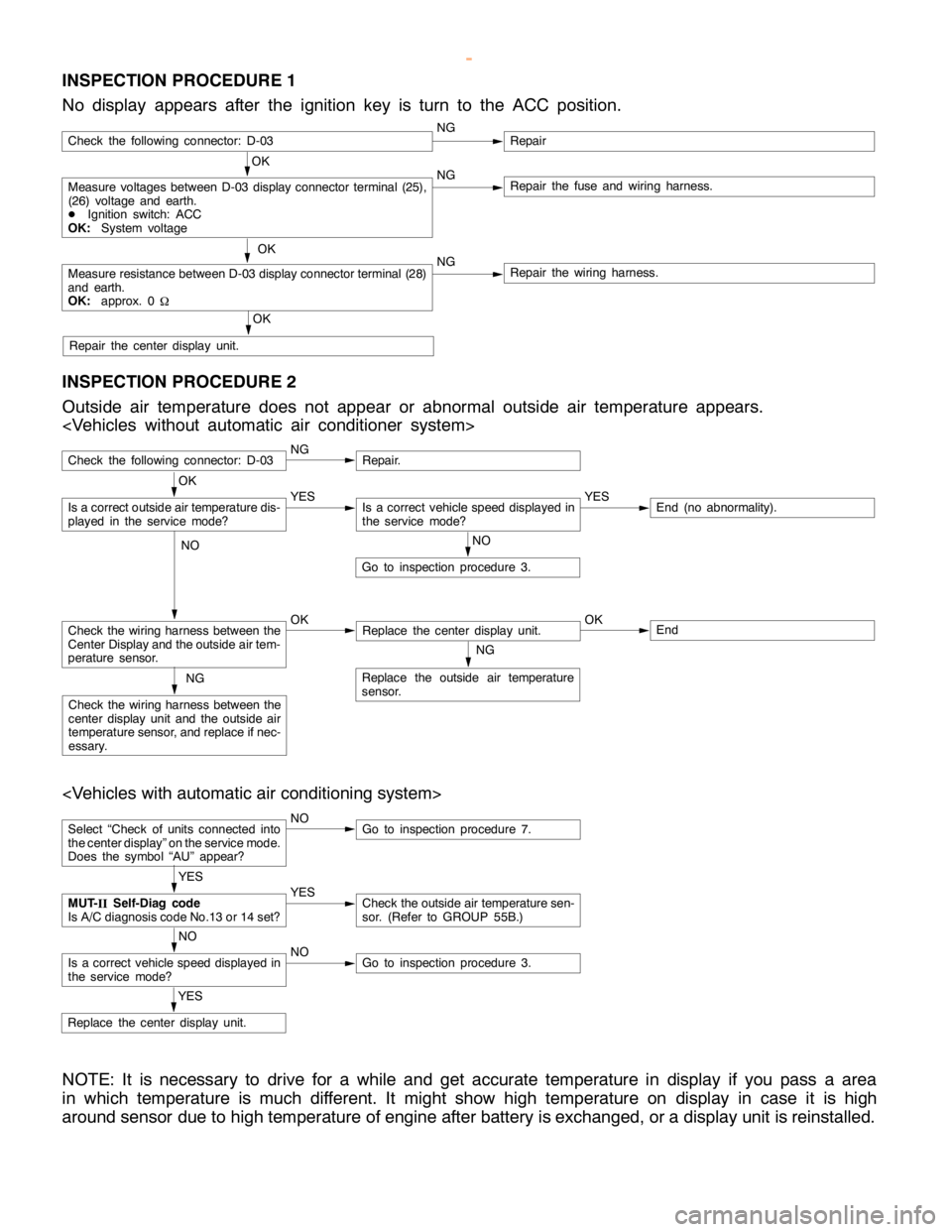
INSPECTION PROCEDURE 1
No display appears after the ignition key is turn to the ACC position.
OK
Measure voltages between D-03 display connector terminal (25),
(26) voltage and earth.
DIgnition switch: ACC
OK:System voltageNGRepair the fuse and wiring harness.
OK
Measure resistance between D-03 display connector terminal (28)
and earth.
OK:approx. 0
WNGRepair the wiring harness.
OK
Repair the center display unit.
Check the following connector: D-03NGRepair
INSPECTION PROCEDURE 2
Outside air temperature does not appear or abnormal outside air temperature appears.
Check the following connector: D-03NGRepair.
NO
Go to inspection procedure 3.
Check the wiring harness between the
Center Display and the outside air tem-
perature sensor.OKReplace the center display unit.OKEnd
NG
Replace the outside air temperature
sensor.NG
Check the wiring harness between the
center display unit and the outside air
temperature sensor, and replace if nec-
essary.
OK
Is a correct outside air temperature dis-
played in the servicemode?YESIs a correct vehicle speed displayed in
the servicemode?YESEnd (no abnormality).
NO
Select “Check of units connected into
the center display” on the service mode.
Does the symbol “AU” appear?NOGo to inspection procedure 7.
YES
Replace the center display unit.
YES
MUT-
IISelf-Diag code
Is A/C diagnosis code No.13 or 14 set?YESCheck the outside air temperature sen-
sor. (Refer to GROUP 55B.)
NO
Is a correct vehicle speed displayed in
the servicemode?NOGo to inspection procedure 3.
NOTE: It is necessary to drive for a while and get accurate temperature in display if you pass a area
in which temperature is much different. It might show high temperature on display in case it is high
around sensor due to high temperature of engine after battery is exchanged, or a display unit is reinstalled.
www.WorkshopManuals.co.uk
Purchased from www.WorkshopManuals.co.uk
Page 1633 of 1839

CHASSIS ELECTRICAL -Clock or Center Display54A-63
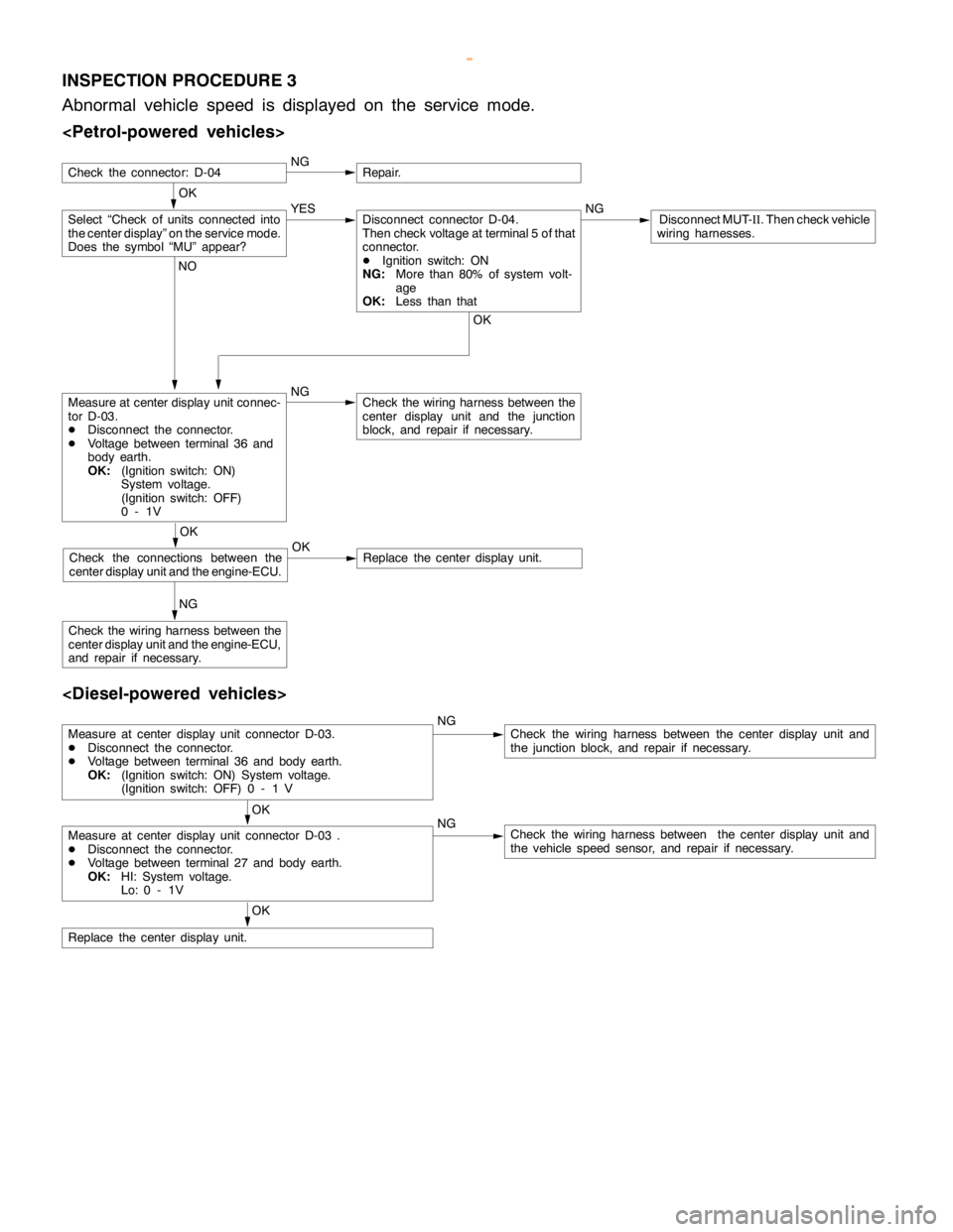
INSPECTION PROCEDURE 3
Abnormal vehicle speed is displayed on the service mode.
OK
NGRepair.
Measure at center display unit connec-
tor D-03.
DDisconnect the connector.
DVoltage between terminal 36 and
body earth.
OK:(Ignition switch: ON)
System voltage.
(Ignition switch: OFF)
0-1VNGCheck the wiring harness between the
center display unit and the junction
block, and repair if necessary.
NG
Check the wiring harness between the
center display unit and the engine-ECU,
and repair if necessary.
Select “Check of units connected into
the center display” on the service mode.
Does the symbol “MU” appear?YES NGDisconnect MUT-
II. Then check vehicle
wiring harnesses.Disconnect connector D-04.
Then check voltage at terminal 5 of that
connector.
DIgnition switch: ON
NG:More than 80% of system volt-
age
OK:Less than that
OK NO
OK
Check the connections between the
center display unit and the engine-ECU.OKReplace the center display unit.
Check the connector: D-04
Measure at center display unit connector D-03.
DDisconnect the connector.
DVoltage between terminal 36 and body earth.
OK:(Ignition switch: ON) System voltage.
(Ignition switch: OFF) 0 - 1 VNGCheck the wiring harness between the center display unit and
the junction block, and repair if necessary.
OK
Measure at center display unit connector D-03 .
DDisconnect the connector.
DVoltage between terminal 27 and body earth.
OK:HI: System voltage.
Lo: 0 - 1VNGCheck the wiring harness between the center display unit and
the vehicle speed sensor, and repair if necessary.
OK
Replace the center display unit.
www.WorkshopManuals.co.uk
Purchased from www.WorkshopManuals.co.uk
Page 1634 of 1839

CHASSIS ELECTRICAL -Clock or Center Display54A-64
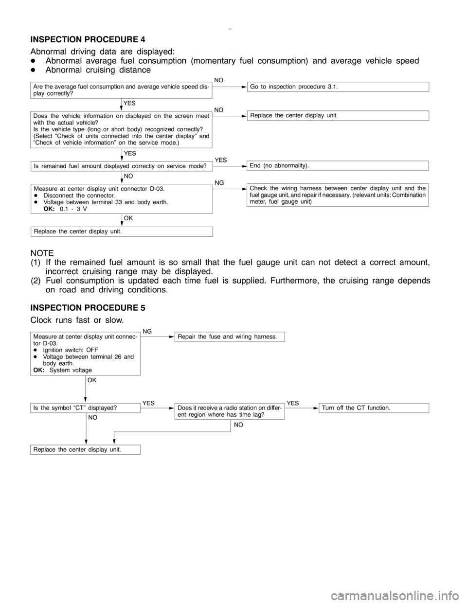
INSPECTION PROCEDURE 4
Abnormal driving data are displayed:
DAbnormal average fuel consumption (momentary fuel consumption) and average vehicle speed
DAbnormal cruising distance
Are the average fuel consumption and average vehicle speed dis-
play correctly?NOGo to inspection procedure 3.1.
YES
Does the vehicle information on displayed on the screen meet
with the actual vehicle?
Is the vehicle type (long or short body) recognized correctly?
(Select “Check of units connected into the center display” and
“Check of vehicle information” on the service mode.)NOReplace the center display unit.
YES
Is remained fuel amount displayed correctly on servicemode?YESEnd (no abnormality).
NO
Measure at center display unit connector D-03.
DDisconnect the connector.
DVoltage between terminal 33 and body earth.
OK:0.1 - 3 VNGCheck the wiring harness between center display unit and the
fuel gauge unit, and repair ifnecessary. (relevant units: Combination
meter, fuel gauge unit)
OK
Replace the center display unit.
NOTE
(1) If the remained fuel amount is so small that the fuel gauge unit can not detect a correct amount,
incorrect cruising range may be displayed.
(2) Fuel consumption is updated each time fuel is supplied. Furthermore, the cruising range depends
on road and driving conditions.
INSPECTION PROCEDURE 5
Clock runs fast or slow.
NGRepair the fuse and wiring harness.
OK
YES
Does it receive a radio station on differ-
ent region where has timelag?YESTurn off the CT function.
NO
Replace the center display unit.
Measure at center display unit connec-
tor D-03.
DIgnition switch: OFF
DVoltage between terminal 26 and
body earth.
OK:System voltage
Is the symbol “CT” displayed?
NO
www.WorkshopManuals.co.uk
Purchased from www.WorkshopManuals.co.uk