2000 MITSUBISHI MONTERO display
[x] Cancel search: displayPage 618 of 1839

DIESEL FUEL <4D5-stepIII>-Troubleshooting13E-8
INSPECTION CHART FOR DIAGNOSIS CODES
Code No.Diagnosis itemReference
page
11Accelerator pedal position sensor (main) system13E-9
12*Boost pressure sensor system13E-10
13Barometric pressure sensor (ECU built-in) system13E-11
14Fuel temperature sensor system13E-11
15Engine coolant temperature sensor system13E-12
16Boost air temperature sensor system13E-12
17Vehicle speed sensor system13E-13
18Pump speed sensor system13E-14
21Crank angle sensor system13E-15
23Idle switch (accelerator pedal position sensor built-in) system13E-16
25*Timer piston position sensor system13E-17
26*Control sleeve position sensor system13E-18
27Accelerator pedal position sensor (sub) system13E-19
41*Throttle solenoid valve system13E-20
43Timing control valve system13E-21
46Injection volume adjusting ROM system13E-22
48*GE actuator (in the middle of control sleeve position sensor inoperative) system13E-23
49*Over boost (variable geometry control pressure sensor system malfunction)13E-24
51EGR valve position sensor system13E-25
52Variable geometry control pressure sensor system13E-26
54Immobilizer system13E-27
Caution
If the above-mentioned diagnosis code number with the asterisks can be displayed along with another
code number in parentheses simultaneously, check the other code number before replacing the
engine-ECU.
12 (41, 49), 26 (48), 25 (43), 41 (12, 49), 48 (26), 49 (12, 41)
www.WorkshopManuals.co.uk
Purchased from www.WorkshopManuals.co.uk
Page 637 of 1839

DIESEL FUEL <4D5-stepIII>-Troubleshooting13E-27
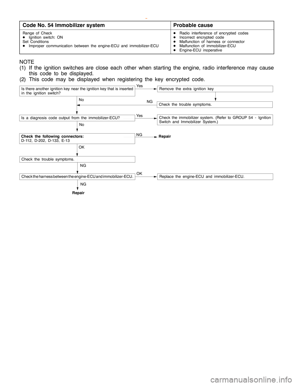
Code No. 54 Immobilizer systemProbable cause
Range of Check
DIgnition switch: ON
Set Conditions
DImproper communication between the engine-ECU and immobilizer-ECUDRadio interference of encrypted codes
DIncorrect encrypted code
DMalfunction of harness or connector
DMalfunction of immobilizer-ECU
DEngine-ECU inoperative
NOTE
(1) If the ignition switches are close each other when starting the engine, radio interference may cause
this code to be displayed.
(2) This code may be displayed when registering the key encrypted code.
Is there another ignition key near the ignition key that is inserted
in the ignition switch?Ye sRemove the extra ignition key
No
Check the following connectors:
D-112, D-202, D-133, E-13NG
Repair
No
Is a diagnosis code output from the immobilizer-ECU?Ye sCheck the immobilizer system. (Refer to GROUP 54 - Ignition
Switch and Immobilizer System.)
NG OK
Check the trouble symptoms.
Check the harness between the engine-ECU and immobilizer-ECU.OKReplace the engine-ECU and immobilizer-ECU.
Check the trouble symptoms. NG
RepairNG
www.WorkshopManuals.co.uk
Purchased from www.WorkshopManuals.co.uk
Page 639 of 1839

DIESEL FUEL <4D5-stepIII>-Troubleshooting13E-29
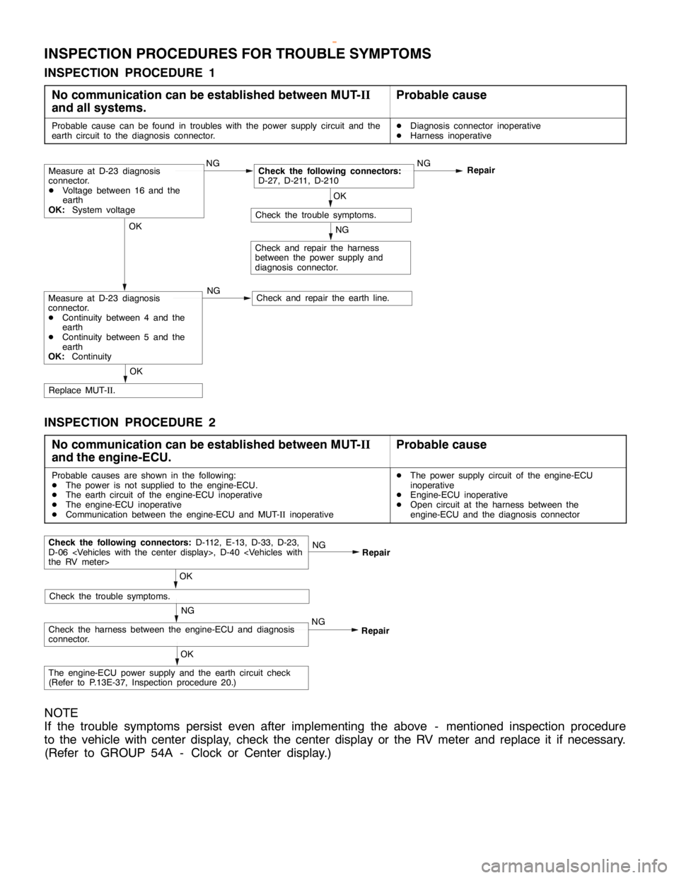
INSPECTION PROCEDURES FOR TROUBLE SYMPTOMS
INSPECTION PROCEDURE 1
No communication can be established between MUT-II
and all systems.
Probable cause
Probable cause can be found in troubles with the power supply circuit and the
earth circuit to the diagnosis connector.DDiagnosis connector inoperative
DHarness inoperative
OK
Check and repair the earth line.
OK
Replace MUT-II.
NG
Check and repair the harness
between the power supply and
diagnosis connector.
OK
Check the trouble symptoms.NG
Repair
NGCheck the following connectors:
D-27, D-211, D-210
NGMeasure at D-23 diagnosis
connector.
DVoltage between 16 and the
earth
OK:System voltage
Measure at D-23 diagnosis
connector.
DContinuity between 4 and the
earth
DContinuity between 5 and the
earth
OK:Continuity
INSPECTION PROCEDURE 2
No communication can be established between MUT-II
and the engine-ECU.
Probable cause
Probable causes are shown in the following:
DThe power is not supplied to the engine-ECU.
DThe earth circuit of the engine-ECU inoperative
DThe engine-ECU inoperative
DCommunication between the engine-ECU and MUT-IIinoperativeDThe power supply circuit of the engine-ECU
inoperative
DEngine-ECU inoperative
DOpen circuit at the harness between the
engine-ECU and the diagnosis connector
NG
Check the harness between the engine-ECU and diagnosis
connector.NGRepair
OK
Check the trouble symptoms.
Check the following connectors:D-112, E-13, D-33, D-23,
D-06
Repair
OK
The engine-ECU power supply and the earth circuit check
(Refer to P.13E-37, Inspection procedure 20.)
NOTE
If the trouble symptoms persist even after implementing the above - mentioned inspection procedure
to the vehicle with center display, check the center display or the RV meter and replace it if necessary.
(Refer to GROUP 54A - Clock or Center display.)
www.WorkshopManuals.co.uk
Purchased from www.WorkshopManuals.co.uk
Page 646 of 1839

DIESEL FUEL <4D5-stepIII>-Troubleshooting13E-36
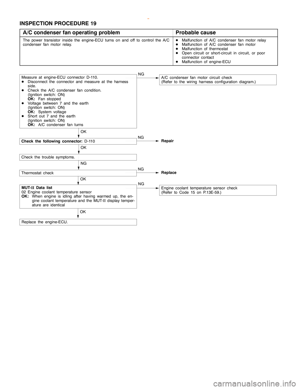
INSPECTION PROCEDURE 19
A/C condenser fan operating problem
Probable cause
The power transistor inside the engine-ECU turns on and off to control the A/C
condenser fan motor relay.DMalfunction of A/C condenser fan motor relay
DMalfunction of A/C condenser fan motor
DMalfunction of thermostat
DOpen circuit or short-circuit in circuit, or poor
connector contact
DMalfunction of engine-ECU
Check the following connector:D-110
OK
Measure at engine-ECU connector D-110.
DDisconnect the connector and measure at the harness
side.
DCheck the A/C condenser fan condition.
(Ignition switch: ON)
OK:Fan stopped
DVoltage between 7 and the earth
(Ignition switch: ON)
OK:System voltage
DShort out 7 and the earth
(Ignition switch: ON)
OK:A/C condenser fan turnsNGA/C condenser fan motor circuit check
(Refer to the wiring harness configuration diagram.)
OK
MUT-IIData list
02 Engine coolant temperature sensor
OK:When engine is idling after having warmed up, the en-
gine coolant temperature and the MUT-IIdisplay temper-
ature are identicalNGEngine coolant temperature sensor check
(Refer to Code 15 on P.13E-59.)
Check the trouble symptoms.OK
Replace the engine-ECU.NG
Repair
Thermostat checkNG
NGReplace
OK
www.WorkshopManuals.co.uk
Purchased from www.WorkshopManuals.co.uk
Page 651 of 1839

DIESEL FUEL <4D5-stepIII>-Troubleshooting13E-41
Item
No.Reference
page Code No.
or inspec-
tion proce-
dure No. Value to be
determined
as normal Inspection conditions Check item
06Vehicle
speed
sensorWhen drivingCompare the engine
speed displayed in the
speed meter with that
in MUT-IIMatchedCode No.
1713E-13
07Pump
speedEngine: CrankingCompare the engine
speed displayed in theMatchedCode No.
1813E-14
speed
sensorEngine: Idling
speeddisplayedinthe
tachometer with that in
MUT-II
18
08Crank angle
sensorEngine: CrankingCompare the engine
speed displayed in theMatchedCode No.
2113E-15
sensor
Engine: Idling
speeddisplayedinthe
tachometer with that in
MUT-II
21
09Accelerator
pedal posi-
tionsensor
Ignition switch: ONAccelerator pedal:
Idling position1,015 - 1,055
mVCode No.
1113E-9
tion sensor
(main)Accelerator pedal:
Fully opened position4,035 - 4,500
mV or higher
10Accelerator
pedal posi-
ti
Ignition switch: ONAccelerator pedal:
Idling position0%Code No.
1113E-9
pp
tion sensor
(main)Accelerator pedal:
Fully opened position99 - 100 %
11System volt-
ageIgnition switch: ONSystem volt-
ageProcedure
No. 2013E-37
13Timing
tl
Engine: After warming
thi
Idling70 - 90 %Code No.
25N
13E-17g
control
valve*1
gg
up the engineWhen engine is
suddenly racedChanges25 or No.
4313E-21
14EGR com-
dl
Engine: After warming
thi
Idling0 - 100 %*2–-
mand value
gg
up the engineWhen engine is
suddenly racedMomentarily
decreases
17Control
sleeve posi-Engine: After warming
up the engineIdling2.1 - 2.5 VCode No.
2613E-18
sleeveposi
tion (target
value)
uptheengine
2,500 r/min (no load)1.8 - 2.2 V
26
18Actual injec-
titi i
Engine: After warming
thi
Idling0.7 - 1.2 V––j
tion timing
gg
up the engineWhen engine is
suddenly racedIncreases
19Injection
ti i
Engine: After warming
thi
Idling0.7 - 1.2 V––j
timing com-
mand value
gg
up the engineWhen engine is
suddenly racedIncreases
21GE actuatorEngine: After warming
uptheengine
Idling0%Code No.
26orNo
13E-18
13E 23upthe engine2,500 r/min18 - 38 %26orNo.
4813E-23
23Control
sleeve posi-Engine: After warming
up the engineIdling2.1 - 2.5 VCode No.
2613E-18
sleeveposi
tion (actual
l)
uptheengine
2,500 r/min (no load)1.8 - 2.2 V
26
(
value)2,500r/min(noload)1.82.2V
24Accelerator
pedal posi-
ti
Ignition switch: ONAccelerator pedal:
Idling position1,015 - 1,055
mVCode No.
2713E-19
pp
tion sensor
(sub)Accelerator pedal:
Fully opened position4,035 - 4,500
mV or higher
www.WorkshopManuals.co.uk
Purchased from www.WorkshopManuals.co.uk
Page 827 of 1839

ENGINE AND EMISSION CONTROL -Auto-cruise Control System17-25
DATA LIST REFERENCE TABLE
For the data, which is input to the engine-ECU
<6G7-M/T, 4M4>, engine-A/T-ECU <6G7-A/T> andthrottle valve controller <6G7>, the following items
can be read out by using the MUT-II
.
HOW TO READ OUT DATA LIST
1. Connect the MUT-II
to the 16-pin diagnosis
connector.
Caution
Turn off the ignition switch befor connecting
and disconnecting the MUT-II
.2. Turn the ignition switch to “ON” position.
3. Select “auto-cruise control” on the MUT-II
menu, and then read out the data list.
<6G7>
Terminal
No.Check itemCheck conditionsNormal condition
01Auto-cruiseMAINMAIN switch: ONON
control
switchMAIN switch: OFFOFF
02SETMAIN switch:SET switch: ONON
(COAST)ONSET switch: OFFOFF
03RESUMERESUME switch: ONON
(ACCEL)RESUME switch: OFFOFF
04CANCELCANCEL switch: ONON
CANCEL switch: OFFOFF
05Stop lamp switchBrake pedal: DepressedON
(for stop lamp circuit)Brake pedal: ReleasedOFF
06Stop lamp switchBrake pedal: DepressedOFF
(for auto-cruise control
circuit)
Brake pedal: ReleasedON
07Clutch switch
Brake pedal: ReleasedOFF
Inhibitor switchSelector lever: “N“, “P” positionON
Selector lever: Other than “N“, “P” positionOFF
08Accelerator switchAccelerator pedal: ReleasedON
(Idle position switch)Accelerator pedal: DepressedOFF
09Auto-cruise controlAuto-cruise control system: ActivatedON
systemAuto-cruise control system: Not activatedOFF
10Vehicle speed sensorRoad test the vehicleThe speedometer and
the MUT-IIdisplay the
same value.
www.WorkshopManuals.co.uk
Purchased from www.WorkshopManuals.co.uk
Page 828 of 1839

ENGINE AND EMISSION CONTROL -Auto-cruise Control System17-26
Terminal
No.Normal condition Check conditions Check item
11Throttle position sensorAccelerator pedal: Fully depressed450 - 800 mV
Accelerator pedal: DepressedThe more deeply the
pedal is depressed, the
higher value the MUT-
IIdisplay
Accelerator pedal: Release4,200 - 4,900 mV
12Accelerator pedalAccelerator pedal: Fully depressed985 - 1,085 mV
position sensorAccelerator pedal: DepressedThe more deeply the
pedal is depressed, the
higher value the MUT-
IIdisplay
Accelerator pedal: Release4,000 mV or more
<4M4>
Terminal
No.Check itemCheck conditionsNormal condition
01Auto-cruiseMAINMAIN switch: ONON
control
switchMAIN switch: OFFOFF
02SETMAIN switch:SET switch: ONON
(COAST)ONSET switch: OFFOFF
03RESUMERESUME switch: ONON
(ACCEL)RESUME switch: OFFOFF
04CANCELCANCEL switch: ONON
CANCEL switch: OFFOFF
05Stop lamp switchBrake pedal: DepressedON
(for stop lamp circuit)Brake pedal: ReleasedOFF
06Stop lamp switchBrake pedal: DepressedOFF
(for auto-cruise control
circuit)
Brake pedal: ReleasedON
07Clutch switch
Brake pedal: ReleasedOFF
Inhibitor switchSelector lever: “N”, “P” positionON
Selector lever: Other than “N”, “P” positionOFF
08Accelerator switchAccelerator pedal: ReleasedON
(Idle position switch)Accelerator pedal: DepressedOFF
09Auto-cruise controlAuto-cruise control system: ActivatedON
systemAuto-cruise control system: Not activatedOFF
www.WorkshopManuals.co.uk
Purchased from www.WorkshopManuals.co.uk
Page 907 of 1839
