2000 MITSUBISHI MONTERO lock
[x] Cancel search: lockPage 1691 of 1839

SWS -General InformationSWS -General Information54B-5
HEADLAMP WASHER
If the headlamp washer switch at the steering
column is placed in the ON position when the ignition
switch is in the ACC or ON position and theheadlamp switch is in the ON position, the headlamp
washer drive signal is turned ON for 0.5 second.
IGNITION KEY HOLE ILLUMINATION LAMP
When the ignition switch is turned to LOCK (OFF) or
ACC position with the driver’s door opened, the
ignition key hole illumination lamp is illuminated.
If the door is closed in that state, the lamp goes out
after 30 seconds. Vehicles with keyless entrysystem, it illuminates for 30 seconds after the
ignition key is removed. In either case the lamp goes
out when the ignition switch is turned to ON position.
HEADLAMP
Headlamp Automatic Shutdown Function
If the ignition switch is turned to LOCK (OFF) or
ACC position, when the headlamps are on, the
headlamps will be switched off in three minutes.
If the driver’s door is opened within that three-minute
period, the headlamps will be switched off
automatically. This prevents the battery from
discharged.
In addition, if the headlamps are turned on when
the ignition switch is at LOCK (OFF) or ACC position,
the headlamps will not be switched off.Headlamp Dimmer Switch Automatic Reset
Function
This function allows the dimmer switch to be reset
to the low-beam position whenever the headlamp
switch is turned ON.
Daytime Running Lamp (DRL) Function
If the ignition switch is turned to ON when the
headlamps and tail lamps are off, the headlamps
(low-beam) and tail lamps turn on.
FLASHER TIMER
Turn-signal Lamp
When the ignition switch is turned to ON position
and turn-signal lamp switch is placed in the ON
position for right or left turn signaling, the system
generates turn-signal lamp drive signals (flashing
signals).
The system also notifies of a blown turn-signal lamp
bulb by shortening the flashing intervals of the
corresponding indicator lamp.Hazard Warning Lamp
The system detects a change from ON to OFF
of the hazard lamp input signal and activates the
hazard lamps if they are not in operation or
deactivates the lamps if they are operating (reversal
of state between activation and deactivation).
FRONT FOG LAMP
If the front fog lamp switch is turned ON at the
condition that the headlamp or the tail lamp is turned
ON (including the illumination by the automatic
lighting function), the front fog lamp is turned ON.Whenever the tail lamps are turned on at the next
time, the front fog lamps will always be off regardless
of the switch positions. In addition, if the tail lamp
is switched off by the automatic lighting system,
the front fog lamp will also be switched off. However,
the front fog lamp will be illuminated when the tail
lamp is switched on.
www.WorkshopManuals.co.uk
Purchased from www.WorkshopManuals.co.uk
Page 1692 of 1839

SWS -General Information54B-6
REAR FOG LAMP
If the fog lamp switch is turned ON when the
headlamp or the front fog lamp is turned On, the
rear fog lamp is switched ON and OFF alternatively.If the headlamp and the front fog lamp are turned
OFF during lighting of the rear fog lamp, the rear
fog lamp is turned OFF at the same time.
ROOM LAMP
With the room lamp switch in the DOOR position,
the ETACS-ECU controls the room lamp operation
as follows:
DWhen a door is opened from outside or inside
[with the ignition switch turned to LOCK (OFF)
position]:
When a door is opened, the ETACS-ECU
causes the room lamp to be illuminated at the
100% intensity. When the door is closed, it
dims out the room lamp to 65% intensity and
approx. 30 seconds later, turns out the lamp
completely. During this period (timer controlled
period), the room lamp goes out if the ignition
switch is turned to ON position or the doors
are locked.
DWhen a door is opened or closed with the
ignition switch in the ON position:
The room lamp illuminates at 100% intensity
when a door is opened and turned out when
it is closed.
DWhen no door is opened and the ignition key
is removed:When the ignition key is removed with all the
doors closed, the room lamp is illuminated at
an intensity of 100% and turned out approx.
30 seconds later. During that time
(timer-controlled period), the room lamp goes
out if the ignition key is inserted and turned
to ON position or the door locking system is
activated.
DRoom lamp’s answerback operation in
response to door lock control by keyless entry
system:
To allow the driver to ascertain the result of
the door locking/unlocking control action by
the use of the keyless entry system, the
ETACS-ECU causes the room lamp to blink
twice when the doors are locked through the
system and to illuminate for approx. 15 seconds
when the doors are locked.
The room lamp’s answerback operation in
response to a keyless entry system control
action is accompanied by operation of the
hazard warning lamps.
www.WorkshopManuals.co.uk
Purchased from www.WorkshopManuals.co.uk
Page 1694 of 1839

SWS -Troubleshooting54B-8
TROUBLESHOOTING
STANDARD FLOW OF DIAGNOSTIC TROUBLESHOOTING
Refer to GROUP 00 – How to Use Troubleshooting/Inspection Service Points.
DIAGNOSTIC FUNCTION
DIAGNOSIS CODES CHECK
Use the MUT-II
to check a diagnosis code.
(Refer to GROUP 00 – How to Use Troubleshooting/Inspection Service Points.)
NOTE
Connect the MUT-II
to the 16-pin diagnosis connector (black).
INPUT SIGNAL CHECK
1. Use the MUT-II
to check a input signal.
(Refer to GROUP 00 – How to Use Troubleshooting/Inspection Service Points.)
2. In this condition, the following input switches can be checked.
3. If an abnormality is found during the input signal check, carry out troubleshooting while referring
to the Trouble Symptom Check page.
Input Signal Check Function
Input signalBuzzer operation condition
Ignition switch (ACC)Turned from LOCK(OFF) to ACC
Ignition switch (IG1)Turned from ACC to ON
Key reminder switch
(from inserted position)
Hazard warning lamp switchTurned from OFF to ON
Front fog lamp switch
Rear fog lamp switch
Back-up lamp switch
Inhibitor switch (reverse)
washer>Selector lever moved to R position
Rear wiper motor auto-stop signal
is sent before the rear wiper begins to operate)
Driver’s door switchDriver’s door opened from closed condition
Door switchesAll doors closed to any door opened
Front passenger’s or back door lock key cylinder switch
Driver’s door lock actuator switch
position to unlock position or vice versa
www.WorkshopManuals.co.uk
Purchased from www.WorkshopManuals.co.uk
Page 1699 of 1839

SWS -Troubleshooting54B-13
TROUBLE SYMPTOM CHART
Trouble symptomInspection
procedureReference
page
Communication with the MUT-IIis impossible.A-154B-17
BuzzerLight reminder warning buzzer function does not work
normally.B-154B-17
Center display operation annunciation function does not work
normally.B-254B-18
Central door lock-Central door locking system does not work normally.C-154B-18
ing system
Some doors does not lock or unlock.C-254B-19
Some functions of central locking system do not work.C-354B-19
Forgotten key prevention function does not work.C-454B-20
Power windowPower window does not work at all.D-154B-20
Power window main switch can not operate driver’s window.D-254B-21
Power window sub switch can not operate front passenger’s or
rear window.D-354B-22
Power window main switch can not operate front passenger’s
or rear window.D-454B-23
Power window timer function does not work normally.D-554B-23
When the glass is raised, it then lowers automatically.D-654B-24
The glass is not lowered when something is jammed in the
window.D-754B-24
When the glass is fully raised, it then lowers automatically.D-854B-24
Keyless entry sys-Keyless entry system does not operate.E-154B-24
tem
The room lamp and hazard warning lamps do not operate
through the answerback function.E-254B-25
The encrypted code cannot be registered.E-354B-25
SunroofSunroof does not work at all.F-154B-26
Sunroof timer function does not work normally.F-254B-27
Safety mechanism does not function.F-354B-27
www.WorkshopManuals.co.uk
Purchased from www.WorkshopManuals.co.uk
Page 1701 of 1839

SWS -Troubleshooting54B-15
Trouble symptomInspection
procedureReference
page
Rear fog lampRear fog lamp do not illuminate when the rear fog lamp switch
is turned on.N-154B-40
Rear fog lamp do not go out when the headlamps and front fog
lamps are turned off while the rear fog lamp is on.N-254B-40
Room lampRoom lamp does not illuminate.O-154B-41
Room lamp dimming function does not work normally.O-254B-41
Center displayCenter display does not work normally.–GROUP 54A
– Center Dis-
play.
DEFECTS FOUND BY INPUT SIGNAL CHECK
If the input signal check finds a defect, follow the table below to check.
Trouble symptomInspection
procedureReference
page
Ignition switch (ACC) signal is not sent to the ETACS-ECU.P-154B-42
Ignition switch (IG1) signal is not sent to the ETACS-ECU.P-254B-42
Key reminder switch signal is not sent to the ETACS-ECU.P-354B-43
Hazard warning lamp switch signal is not sent to the ETACS-ECU.P-454B-43
Front fog lamp switch signal is not sent to the ETACS-ECU.P-554B-44
Rear fog lamp switch signal is not sent to the ETACS-ECU.P-654B-45
Back-up lamp switch signal is not sent to the ETACS-ECU.
Inhibitor switch (reverse) signal is not sent to the ETACS-ECU.P-854B-46
Rear wiper motor auto-stop signal is not sent to the ETACS-ECU.P-954B-46
Driver’s door switch signal is not sent to the ETACS-ECU.P-1054B-47
Door switches signal is not sent to the ETACS-ECU.
Front passenger’s or back door lock key cylinder switch signal is not sent to the
ETACS-ECU.P-1154B-48
Driver’s door lock actuator switch signal is not sent to the ETACS-ECU.P-1254B-48
www.WorkshopManuals.co.uk
Purchased from www.WorkshopManuals.co.uk
Page 1703 of 1839

SWS -TroubleshootingSWS -Troubleshooting54B-17
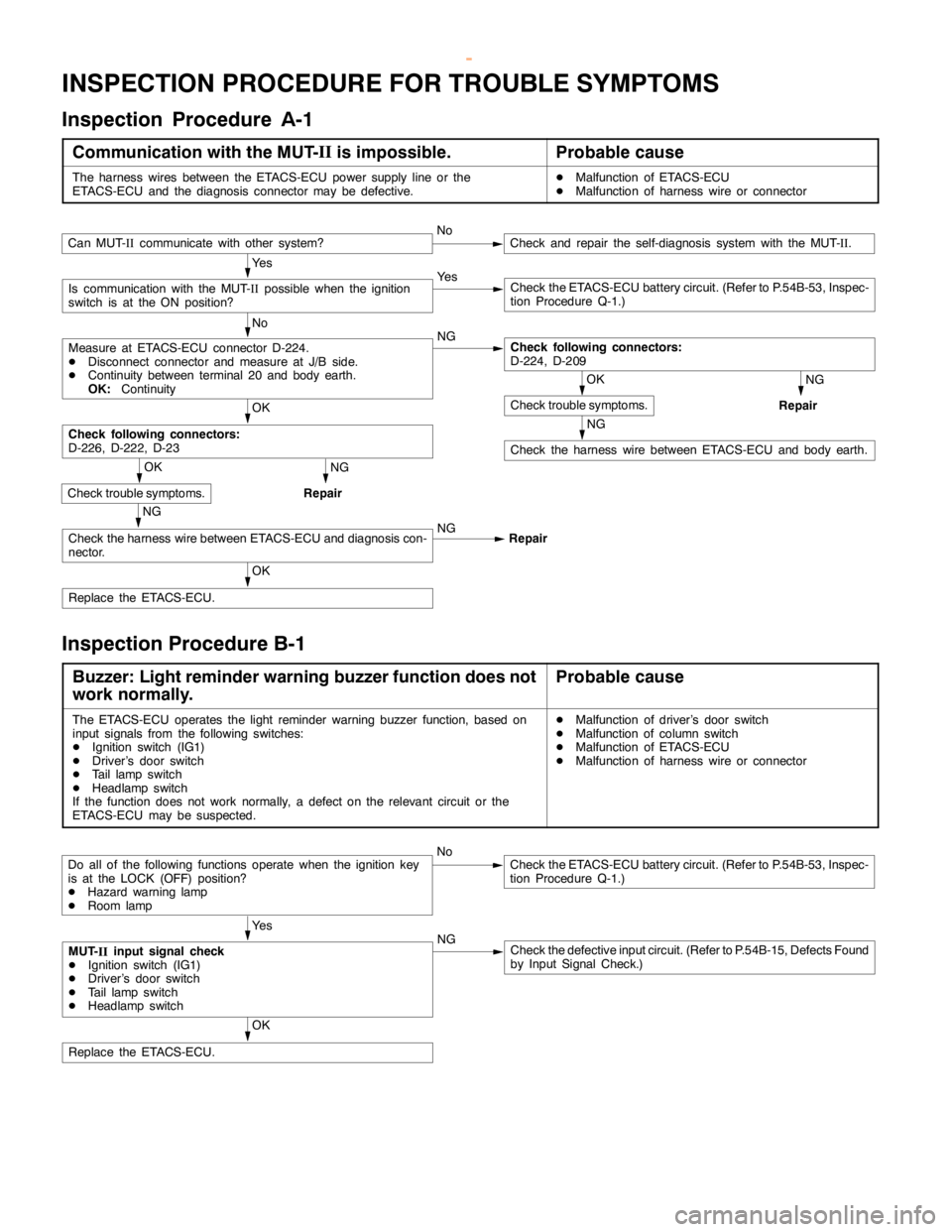
INSPECTION PROCEDURE FOR TROUBLE SYMPTOMS
Inspection Procedure A-1
Communication with the MUT-II
is impossible.Probable cause
The harness wires between the ETACS-ECU power supply line or the
ETACS-ECU and the diagnosis connector may be defective.DMalfunction of ETACS-ECU
DMalfunction of harness wire or connector
Ye s
Ye s
Check the ETACS-ECU battery circuit. (Refer to P.54B-53, Inspec-
tion Procedure Q-1.)
No
NG
NG
Repair
NG
Check the harness wire between ETACS-ECU and body earth.
OK
OK
Replace the ETACS-ECU.
NG
Repair
NG
Check the harness wire between ETACS-ECU and diagnosis con-
nector.NG
Repair
OK
Check trouble symptoms.
Check following connectors:
D-226, D-222, D-23
OK
Check trouble symptoms.
Check following connectors:
D-224, D-209Measure at ETACS-ECU connector D-224.
DDisconnect connector and measure at J/B side.
DContinuity between terminal 20 and body earth.
OK:Continuity
Is communication with the MUT-
IIpossible when the ignition
switch is at the ON position?
Can MUT-
IIcommunicate with other system?NoCheck and repair the self-diagnosis system with the MUT-
II.
Inspection Procedure B-1
Buzzer: Light reminder warning buzzer function does not
work normally.Probable cause
The ETACS-ECU operates the light reminder warning buzzer function, based on
input signals from the following switches:
DIgnition switch (IG1)
DDriver’s door switch
DTail lampswitch
DHeadlamp switch
If the function does not work normally, a defect on the relevant circuit or the
ETACS-ECU may be suspected.DMalfunction of driver’s door switch
DMalfunction of column switch
DMalfunction of ETACS-ECU
DMalfunction of harness wire or connector
NoCheck the ETACS-ECU battery circuit. (Refer to P.54B-53, Inspec-
tion Procedure Q-1.)
Ye s
NG
Check the defective input circuit. (Refer to P.54B-15, Defects Found
by Input Signal Check.)
OK
Replace the ETACS-ECU.
Do all of the following functions operate when the ignition key
is at the LOCK (OFF) position?
DHazard warninglamp
DRoom lamp
MUT-
IIinput signal check
DIgnition switch (IG1)
DDriver’s door switch
DTail lampswitch
DHeadlamp switch
www.WorkshopManuals.co.uk
Purchased from www.WorkshopManuals.co.uk
Page 1704 of 1839

SWS -Troubleshooting54B-18
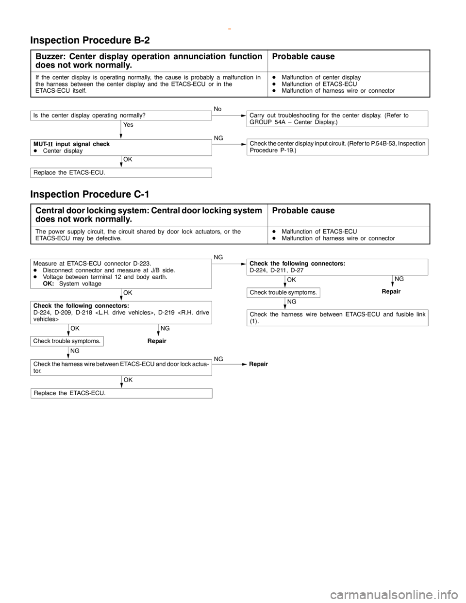
Inspection Procedure B-2
Buzzer: Center display operation annunciation function
does not work normally.Probable cause
If the center display is operating normally, the cause is probably a malfunction in
the harness between the center display and the ETACS-ECU or in the
ETACS-ECU itself.DMalfunction of center display
DMalfunction of ETACS-ECU
DMalfunction of harness wire or connector
Ye s
NG
Check the center display input circuit. (Refer to P.54B-53, Inspection
Procedure P-19.)
OK
Replace the ETACS-ECU.
MUT-
IIinput signal check
DCenter display
Is the center display operating normally?NoCarry out troubleshooting for the center display. (Refer to
GROUP 54A – Center Display.)
Inspection Procedure C-1
Central door locking system: Central door locking system
does not work normally.Probable cause
The power supply circuit, the circuit shared by door lock actuators, or the
ETACS-ECU may be defective.DMalfunction of ETACS-ECU
DMalfunction of harness wire or connector
NG
NG
Repair
NG
Check the harness wire between ETACS-ECU and fusible link
(1).
OK
NG
Repair
NG
NG
Repair
OK
Replace the ETACS-ECU.
Check the harness wire between ETACS-ECU and door lock actua-
tor.
OK
Check trouble symptoms.
Check the following connectors:
D-224, D-209, D-218
Measure at ETACS-ECU connector D-223.
DDisconnect connector and measure at J/B side.
DVoltage between terminal 12 and body earth.
OK:System voltage
OK
Check trouble symptoms.
Check the following connectors:
D-224, D-211, D-27
www.WorkshopManuals.co.uk
Purchased from www.WorkshopManuals.co.uk
Page 1705 of 1839

SWS -Troubleshooting54B-19
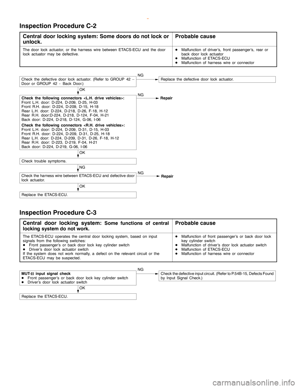
Inspection Procedure C-2
Central door locking system: Some doors do not lock or
unlock.Probable cause
The door lock actuator, or the harness wire between ETACS-ECU and the door
lock actuator may be defective.DMalfunction of driver’s, front passenger’s, rear or
back door lock actuator
DMalfunction of ETACS-ECU
DMalfunction of harness wire or connector
NGReplace the defective door lock actuator.
OK
NG
Repair
OK
Check trouble symptoms.
OK
Replace the ETACS-ECU.
Check the harness wire between ETACS-ECU and defective door
lock actuator.Repair NG NG
Check the following connectors
Front L.H. door: D-224, D-209, D-25, H-03
Front R.H. door: D-224, D-209, D-15, H-18
Rear L.H. door: D-224, D-218, D-26, F-18, H-12
Rear R.H. door:D-224, D-218, D-124, F-04, H-21
Back door: D-224, D-218, D-124, G-06, I-06
Check the following connectors
Front L.H. door: D-224, D-209, D-31, D-15, H-03
Front R.H. door: D-224, D-209, D-31, D-25, H-18
Rear L.H. door: D-224, D-209, D-31, D-26, F-18, H-12
Rear R.H. door: D-223, D-219, F-04, H-21
Back door: D-224, D-219, G-06, I-06
Check the defective door lock actuator. (Refer to GROUP 42 –
Door or GROUP 42 - Back Door.)
Inspection Procedure C-3
Central door locking system:Some functions of central
locking system do not work.Probable cause
The ETACS-ECU operates the central door locking system, based on input
signals from the following switches:
DFront passenger’s or back door lock key cylinder switch
DDriver’s door lock actuator switch
If the system does not work normally, a defect on the relevant circuit or the
ETACS-ECU may be suspected.DMalfunction of front passenger’s or back door lock
key cylinder switch
DMalfunction of driver’s door lock actuator switch
DMalfunction of ETACS-ECU
DMalfunction of harness wire or connector
NGCheck the defective input circuit. (Refer to P.54B-15, Defects Found
by Input Signal Check.)
OK
Replace the ETACS-ECU.
MUT-
IIinput signal check
DFront passenger’s or back door lock key cylinder switch
DDriver’s door lock actuator switch
www.WorkshopManuals.co.uk
Purchased from www.WorkshopManuals.co.uk