2000 MITSUBISHI MONTERO lock
[x] Cancel search: lockPage 1165 of 1839

POWER PLANT MOUNT - No.1 Crossmember32-7
No.1 CROSSMEMBER
REMOVAL AND INSTALLATION
Caution
1. Before removing the steering wheel and airbag module assembly, always refer to GROUP 52B
- Service Precautions, Airbag Module and Clock Spring. Also, set the front wheels so that
they are facing straight forward, and remove the ignition key. If you fail to do this, the SRS
clock spring will be damaged, causing the SRS airbag to be inoperative and serious injury.
2. *: Indicates parts which should be initially tightened, and then fully tightened after placing
the vehicle horizontally and loading the full weight of the engine on the vehicle body.
Pre-removal Operation
DUnder Cover Removal
DDrive Shaft Removal
(Refer to GROUP 26.)
DDifferential Carrier and No.2 Crossmember
Assembly Removal (Refer to GROUP 26 -
Freewheel Assembly and Differential Carrier.)
DUpper Arm Removal
(Refer to GROUP 33A.)
DLower Arm Removal
(Refer to GROUP 33A.)
DStabilizer Bar Removal
(Refer to GROUP 33A.)
DEngine Oil Cooler Removal<6G7>
(Refer to GROUP 12.)
DAir Cleaner Removal<4M4>
(Refer to GROUP 15.)
DIntercooler Removal<4M4>
(Refer to GROUP 15.)
DEngine Cover Removal
(Refer to GROUP 11A - Timing Belt.)
DRadiator Removal
(Refer to GROUP 14.)
DPower Steering Fluid Draining
(Refer to GROUP 37A - On - vehicle Service.)Post - installation Operations
DDifferential Carrier and No.2 Crossmember
Assembly Installation (Refer to GROUP 26 -
Freewheel Assembly and Differential Carrier.)
DDrive Shaft Installation
(Refer to GROUP 26.)
DLower Arm Installation
(Refer to GROUP 33A.)
DUpper Arm Installation
(Refer to GROUP 33A.)
DStabilizer Bar Installation
(Refer to GROUP 33A.)
DAir Cleaner Installation<4M4>
(Refer to GROUP 15.)
DIntercooler Installation<4M4>
(Refer to GROUP 15.)
DRadiator Installation
(Refer to GROUP 14.)
DEngine Oil Cooler Installation
(Refer to GROUP 12.)
DPower Steering Fluid Supplying
(Refer to GROUP 37A - On - vehicle Service.)
DPower Steering Fluid Line Bleeding
(Refer to GROUP 37A - On - vehicle Service.)
DPress the dust cover with a finger tocheck whether
the dust cover is cracked or damaged.
DChecking Steering Wheel Position with Wheels
StraightAhead
DFront Wheel AlignmentCheck and Adjustment
(Refer to GROUP 37A - On - vehicle Service.)
DUnder Cover Installation
DEngine Cover Installation
(Refer to GROUP 11A - Timing Belt.)
www.WorkshopManuals.co.uk
Purchased from www.WorkshopManuals.co.uk
Page 1227 of 1839

O
N-V EH IC LE SER VIC E
B RAKE PED AL CHEC K AND ADJU STM EN T
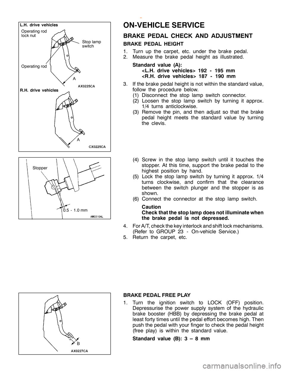
B RAKE PED AL HEIG HT
1 . Turn up th e ca rp et, etc . under th e bra ke pedal.
2 . Measu re th e bra ke pedal heig ht as illu str a te d.
S ta n dard valu e (A ):
< L .H . driv e veh ic le s> 192 -195 mm
< R .H . driv e veh ic le s> 187 -190 mm
3 . If th e bra ke pedalh eig ht is not w it h in th e sta ndard va lu e,
f o llo w th e pro ce dure belo w .
( 1 ) Dis co nnect th e sto p la m p sw it c h co nnecto r.
( 2 ) Loose n th e sto p la m p sw it c h by tu rn in g it appro x.
1 /4 tu rn s antic lo ckw is e .
( 3 ) Rem ove th e pin , and th en adju st so th at th e bra ke
p edal heig ht m eets th e sta ndard va lu e by tu rn in g
t h e cle vis .
( 4 ) Scre w in th e sto p la m p sw it c h until it to uch es th e
s to pper. A tth is tim e, su pport th e bra ke pedal to th e
h ig hest posit io n by hand.
( 5 ) Lock th e sto p la m p sw it c h by tu rn in g it appro x. 1/4
t u rn s clo ckw is e , and co nfir m th at th e cle ara nce
b etw een th e sw it c h plu nger and th e sto pper is as
s h ow n.
( 6 ) Connect th e co nnecto r at th e sto p la m p sw it c h .
C au tio n
C heck th atth e sto p la m pdoes notillu m in ate w hen
t h e bra ke ped al is not dep re ssed .
4 . ForA /T ,c h eck th e ke y in te rlo ck and sh if t lo ck m ech anis m s.
( R efe r to GRO UP 23 -On-v e hic le Serv ic e .)
5 . Retu rn th e ca rp et, etc .
B RAKE PED AL FR EE PLA Y
1 . Turn th e ig nit io n sw it c h to LO CK (O FF) posit io n.
D epre ssu ris e th e pow er su pply syste m of th e hyd ra ulic
b ra ke booste r (H BB) by depre ssin g th e bra ke pedal at
l e ast fo rty tim es until th e pedale ff o rt b eco m es hig h.T hen
p ush th e pedalw it h yo ur fin ger to ch eck th e pedalh eig ht
( fr e e pla y) is wit h in th e sta ndard va lu e.
S ta n dard valu e (B ): 3 –8mm A
L
.H .driv e veh ic le s
R .H .driv e veh ic le s O
pera tin g ro d S
to p la m p
s w it c h S
to pper
0.5 -1.0 mm B
w
ww.W ork sh opM an uals .c o .u k
P urc h ased f r o m w ww.W ork sh opM an uals .c o .u k
Page 1235 of 1839

BASIC BRAKE SYSTEM -On-vehicle ServiceBASIC BRAKE SYSTEM -On-vehicle Service35A-27
BLEEDING
Caution
Specified brake fluid: DOT3 or DOT4
1. Always use the specified brake fluid. Avoid using
a mixture of the specified brake fluid and other fluid.
2. Maintain the fluid reservoir level between the MIN
and MAX marks during the air bleeding.
3. Do not depress the brake pedal hard during the air
bleeding (normal air bleeding) to prevent the pump
motor from operating frequently.
4. After the air bleeding, check that the brake dragging
does not become stronger.
5. If the pedal is depressed with the reservoir cap
removed, the brake fluid may overflow. Do not depress
the brake pedal while the fluid is being added.
NORMAL AIR BLEEDING
After the front brake or the rear brake is removed and installed,
some fluid may remain in the hydraulic brake booster (HBB)
reservoir. In this case, bleed air from the brake caliper.
HBB SYSTEM AIR BLEEDING
If all the brake fluid inside the reservoir is drained due to
the removal and installation of the HBB, bleed air as follows:
Air bleeding from front brake system
1. Turn the ignition switch to the LOCK (OFF) position. Bleed
air from the front brake calipers (right and left) by pumping
the brake pedal.
Pump motor operation
2. Turn the ignition switch ON, and operate the pump motor.
If the pump motor is running free, supply the brake fluid
into the pump motor by depressing the brake pedal three
or four times.
Air bleeding from accumulator system
3. After the pump motor stopped, depress the brake pedal
three or four times with the ignition switch ON. Then
observe the brake fluid in the reservoir. If the brake fluid
looks whitish, wait for a few minutes until it becomes
clear.
4. Repeat step 3 until the brake fluid becomes clear.
www.WorkshopManuals.co.uk
Purchased from www.WorkshopManuals.co.uk
Page 1259 of 1839

1
5
1 5
14
1 3 6
1
0 6
6
6 6
3
1
0
10
8 1
1
1
2
1 4 1
0
C
lip set
B ra ke calip er kit Pad set Seal an d boots kit
S him set
4
4
±5
N
×m
4
4
±5
N
×m 7
.9
±0
.9 N
×m
D is assem bly ste p s
" AA
1. G uid e pin
2 . P ad and clip asse m bly , sh im
3 . S him
4 . P ad and clip asse m bly
5 . P ad asse m bly
6 . P ad clip
" AA
7. Lock pin
8 . B ush in g 9
. C alip er su pport
1 0. P in boot
1 1 . B oot rin g
A A"
12. P is to n boot
A A"
13. P is to n
A B"
14. P is to n se al
1 5. C alip er body
w
ww.W ork sh opM an uals .c o .u k
P urc h ased f r o m w ww.W ork sh opM an uals .c o .u k
Page 1270 of 1839

ABS <4WD> -Troubleshooting35B-7
INSPECTION CHART FOR DIAGNOSIS CODES
Diagnosis code
No.Diagnosis itemReference page
11Wheel speed sensor (FR) system (open circuit or short - circuit)35B-8
12Wheel speed sensor (FL) system (open circuit or short - circuit)35B-8
13Wheel speed sensor (RR) system (open circuit or short - circuit)35B-8
14Wheel speed sensor (RL) system (open circuit or short - circuit)35B-8
15Wheel speed sensor system (output signal abnormality)35B-9
16ABS-ECU or valve relay power supply system (abnormal voltage
drop or rise)35B-10
21Wheel speed sensor (FR) system35B-8
22Wheel speed sensor (FL) system35B-8
23Wheel speed sensor (RR) system35B-8
24Wheel speed sensor (RL) system35B-8
26Center differential lock switch system35B-11, 12
27Rear differential lock switch system35B-11, 12
32G sensor system35B-13
33Stop lamp switch system35B-14
41Control solenoid valve (FR)
systemIf there is no response to the
solenoid valve drive signal35B-15
42Control solenoid valve (FL)
systemcorresponding to each respec-
tive item
43Control solenoid valve (RR)
system
44Control solenoid valve (RL)
system
45Changeover solenoid valve
(FR) system
46Changeover solenoid valve
(FL) system
51Valve relay system (ON problem)35B-16
52Valve relay system(OFFproblem)35B-17
55HBB systemCarry out HBB troubleshoot-
ing. (Refer to GROUP 35A.)
63ABS-ECU system35B-32 (ABS-ECU replace-
ment)
NOTE
*: Code No.16 is erased from the memory if the condition returns to normal.
www.WorkshopManuals.co.uk
Purchased from www.WorkshopManuals.co.uk
Page 1274 of 1839

ABS <4WD> -Troubleshooting35B-11
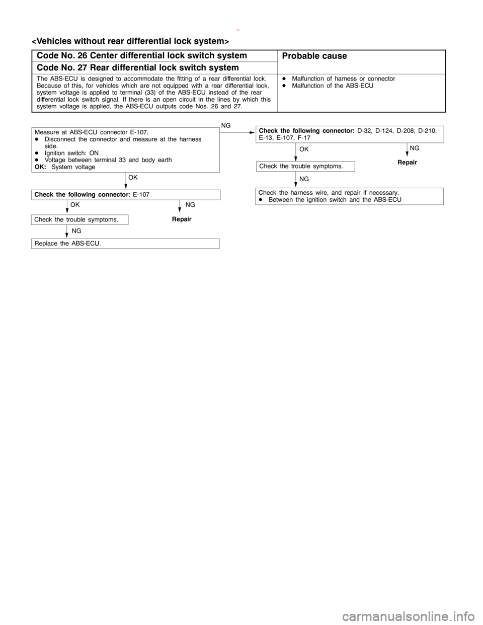
Code No. 26 Center differential lock switch system
Probable cause
Code No. 27 Rear differential lock switch system
The ABS-ECU is designed to accommodate the fitting of a rear differential lock.
Because of this, for vehicles which are notequippedwith a rear differential lock,
system voltage isapplied to terminal(33) of the ABS-ECU instead of the rear
differential lock switch signal. If there is anopencircuit in the lines by which this
system voltage is applied, the ABS-ECU outputs code Nos. 26 and 27.DMalfunction of harness or connector
DMalfunction of the ABS-ECU
NG
OK
Replace the ABS-ECU.
NG
Check the harness wire, and repair if necessary.
DBetween the ignition switch and the ABS-ECU
OK
NG
Repair
Measure at ABS-ECU connector E-107.
DDisconnect the connector and measure at the harness
side.
DIgnition switch: ON
DVoltage between terminal 33 and body earth
OK:System voltage
Check the trouble symptoms.
Check the following connector:D-32, D-124, D-208, D-210,
E-13, E-107, F-17
OK NG
Repair
NG
Check the trouble symptoms.
Check the following connector:E-107
www.WorkshopManuals.co.uk
Purchased from www.WorkshopManuals.co.uk
Page 1275 of 1839

ABS <4WD>-Troubleshooting35B-12
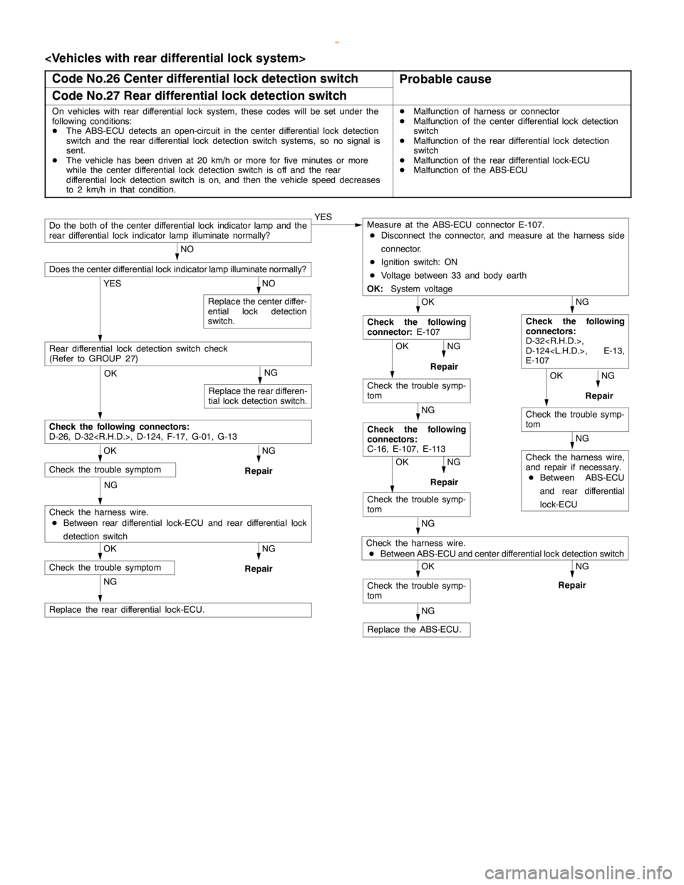
Code No.26 Center differential lock detection switch
Probable cause
Code No.27 Rear differential lock detection switch
On vehicles with rear differential lock system, these codes will be set under the
following conditions:
DThe ABS-ECU detects an open-circuit in the center differential lock detection
switch and the rear differential lock detection switch systems, so no signal is
sent.
DThe vehicle hasbeendriven at 20 km/h or more for five minutes or more
while the center differential lock detection switch is off and the rear
differential lock detection switch is on, and then the vehicle speed decreases
to 2 km/h in that condition.DMalfunction of harness or connector
DMalfunction of the
center differential lock detection
switch
DMalfunction of the
rear differential lock detection
switch
DMalfunction of the
rear differential lock-ECU
DMalfunction of the
ABS-ECU
YES
NG OK
Do the both of the center differential lock indicatorlamp and the
rear differential lock indicatorlamp illuminate normally?YESMeasure at the ABS-ECU connector E-107.
DDisconnect the connector, and measure at the harness side
connector.
DIgnition switch: ON
DVoltage between 33 and body earth
OK:System voltage
NG OK
NO
Does the center differential lock indicatorlamp illuminate normally?
NO
Replace the center differ-
ential lock detection
switch.
Check the following
connector:E-107Check the following
connectors:
D-32
D-124
E-107
NG
Repair
Repair
Check the trouble symp-
tom
Check the trouble symp-
tomOKNG
NG
Check the harness wire,
and repair if necessary.
DBetween ABS-ECU
and rear differential
lock-ECU
Check the following
connectors:
C-16, E-107, E-113
NG OK
Repair
Check the trouble symp-
tom
NG
Check the harness wire.
DBetween ABS-ECU and center differential lock detection switch
NG
Repair
OK
Check the trouble symp-
tom
Replace the ABS-ECU.
Rear differential lock detection switch check
(Refer to GROUP 27)
NG
OK
Check the following connectors:
D-26, D-32
NG
Repair
OK
Check the trouble symptom
NG
Check the harness wire.
DBetween rear differential lock-ECU and rear differential lock
detection switch
NG
Repair
OK
Check the trouble symptom
NG
Replace the rear differential lock-ECU.
NG
Replace the rear differen-
tial lock detection switch.
www.WorkshopManuals.co.uk
Purchased from www.WorkshopManuals.co.uk
Page 1281 of 1839

ABS <4WD> -Troubleshooting35B-18
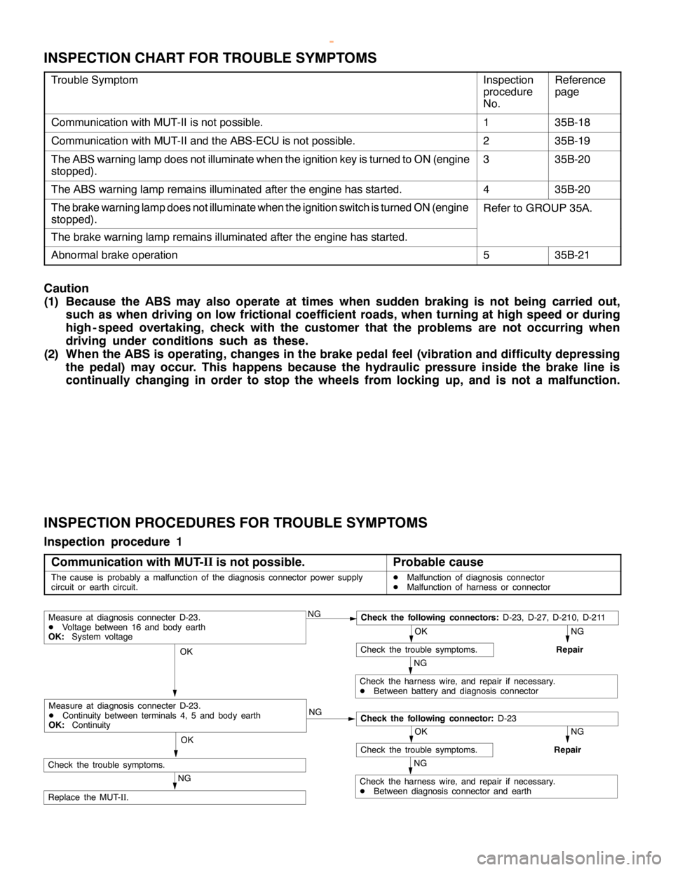
INSPECTION CHART FOR TROUBLE SYMPTOMS
Trouble SymptomInspection
procedure
No.Reference
page
Communication with MUT-II is not possible.135B-18
Communication with MUT-II and the ABS-ECU is not possible.235B-19
The ABS warning lamp does not illuminate when the ignition key is turned to ON (engine
stopped).335B-20
The ABS warning lamp remains illuminated after the engine has started.435B-20
The brake warning lamp does not illuminate when the ignition switch is turned ON (engine
stopped).Refer to GROUP 35A.
The brake warning lamp remains illuminated after the engine has started.
Abnormal brake operation535B-21
Caution
(1) Because the ABS may also operate at times when sudden braking is not being carried out,
such as when driving on low frictional coefficient roads, when turning at high speed or during
high - speed overtaking, check with the customer that the problems are not occurring when
driving under conditions such as these.
(2) When the ABS is operating, changes in the brake pedal feel (vibration and difficulty depressing
the pedal) may occur. This happens because the hydraulic pressure inside the brake line is
continually changing in order to stop the wheels from locking up, and is not a malfunction.
INSPECTION PROCEDURES FOR TROUBLE SYMPTOMS
Inspection procedure 1
Communication with MUT-II
is not possible.
Probable cause
The cause is probably a malfunction of the diagnosis connector power supply
circuit or earth circuit.DMalfunction of diagnosis connector
DMalfunction of harness or connector
NGCheck the following connectors:D-23, D-27, D-210, D-211
NG
Repair
OK
Check the trouble symptoms.
NG
Check the harness wire, and repair if necessary.
DBetween battery and diagnosis connector
OK
NG
NG
Repair
OK
Check the trouble symptoms.
NG
Check the harness wire, and repair if necessary.
DBetween diagnosis connector and earth
OK
NG
Replace the MUT-
II.
Measure at diagnosis connecter D-23.
DVoltage between 16 and body earth
OK:System voltage
Check the following connector:D-23
Measure at diagnosis connecter D-23.
DContinuity between terminals 4, 5 and body earth
OK:Continuity
Check the trouble symptoms.
www.WorkshopManuals.co.uk
Purchased from www.WorkshopManuals.co.uk