2000 MITSUBISHI MONTERO lock
[x] Cancel search: lockPage 494 of 1839

DIESEL FUEL <4M4> -Service Specifications/Sealant13C-3
SERVICE SPECIFICATIONS
ItemStandard value
Accelerator pedal position sensor reference voltage V0.985 - 1.085
Accelerator pedal position sensor resistance kW3.5 - 6.5
Boost air temperature sensor (Intake air temperatureWhen the temperature is 20_C2.3 - 2.9
sensor) resistance kWWhen the temperature is 80_C0.30 - 0.39
Engine coolant temperature sensor resistance kWWhen the temperature is 20_C2.3 - 2.6
When the temperature is 80_C0.30 - 0.34
Fuel cut solenoid valve resistanceW6.8 - 9.2
Timing control valve resistanceW10.8 - 11.2
Timer piston position sensor resistanceWConnector terminals No.1 - No.2160 - 168
Connector terminals No.1 - No.380 - 84
Connector terminals No.2 - No.380 - 84
Control sleeve position sensor resistanceWConnector terminals No.4 - No.1211.2 - 12.4
Connector terminals No.4 - No.85.6 - 6.2
Connector terminals No.8 - No.125.6 - 6.2
GE actuator (electronic governor) resistanceWConnector terminals No.6 - No.100.64 - 0.72
Fuel temperature sensor resistance kWConnector terminals No.7 - No.111.4 - 2.6
Engine speed sensor resistance kW2.15
Main/sub throttle solenoid valve resistanceW36 - 44
SEALANT
ItemSpecified sealant
Engine coolant temperature sensor3M Nut Locking Part No.4171 or equivalent
www.WorkshopManuals.co.uk
Purchased from www.WorkshopManuals.co.uk
Page 515 of 1839

DIESEL FUEL <4M4> -Troubleshooting13C-24
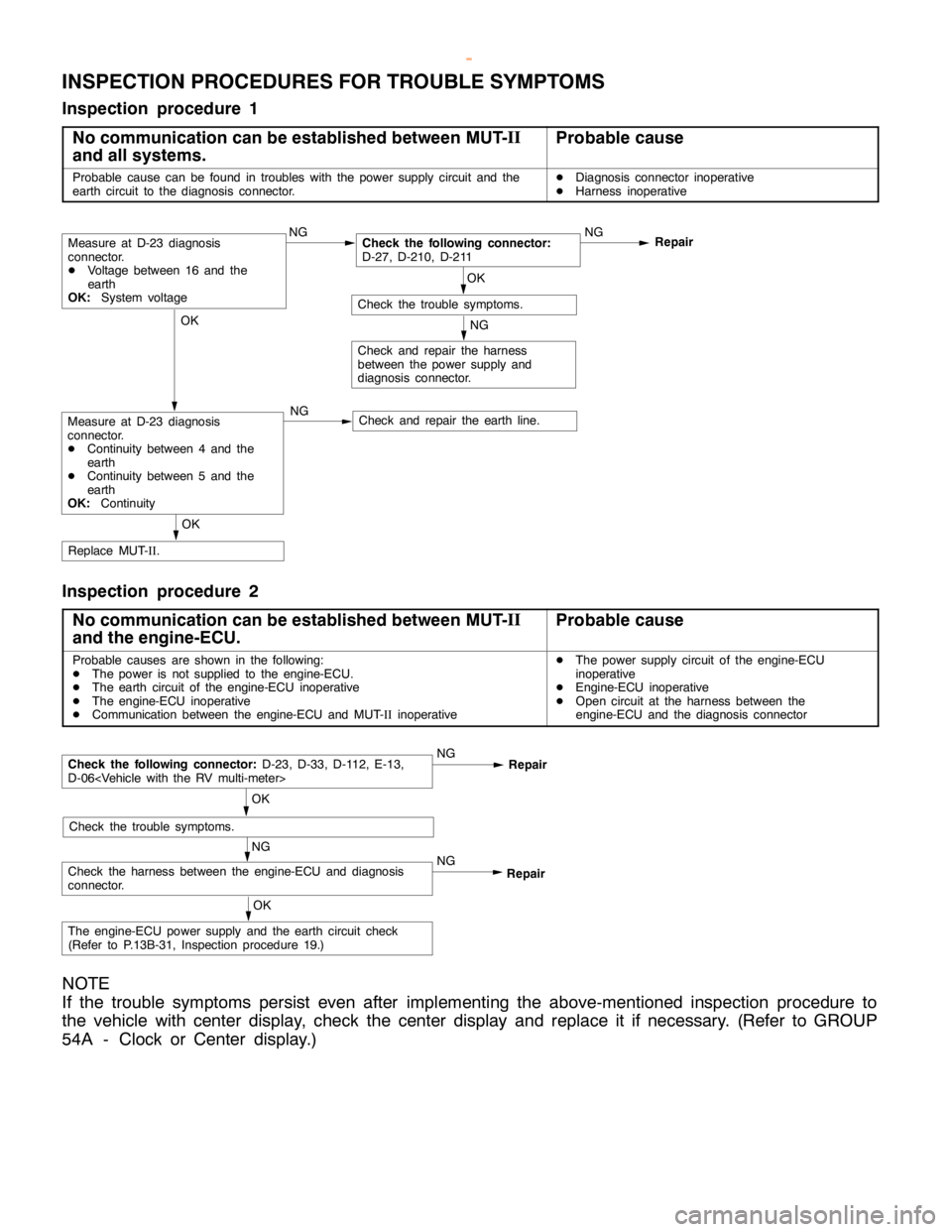
INSPECTION PROCEDURES FOR TROUBLE SYMPTOMS
Inspection procedure 1
No communication can be established between MUT-II
and all systems.
Probable cause
Probable cause can be found in troubles with the power supply circuit and the
earth circuit to the diagnosis connector.DDiagnosis connector inoperative
DHarness inoperative
OK
Check and repair the earth line.
OK
Replace MUT-II.
NG
Check and repair the harness
between the power supply and
diagnosis connector.
OK
Check the trouble symptoms.NG
Repair
NGCheck the following connector:
D-27, D-210, D-211
NGMeasure at D-23 diagnosis
connector.
DVoltage between 16 and the
earth
OK:
System voltage
Measure at D-23 diagnosis
connector.
DContinuity between 4 and the
earth
DContinuity between 5 and the
earth
OK:
Continuity
Inspection procedure 2
No communication can be established between MUT-II
and the engine-ECU.
Probable cause
Probable causes are shown in the following:
DThe power is not supplied to the engine-ECU.
DThe earth circuit of the engine-ECU inoperative
DThe engine-ECU inoperative
DCommunication between the engine-ECU and MUT-IIinoperativeDThe power supply circuit of the engine-ECU
inoperative
DEngine-ECU inoperative
DOpen circuit at the harness between the
engine-ECU and the diagnosis connector
NG
Check the harness between the engine-ECU and diagnosis
connector.NGRepair
OK
Check the trouble symptoms.
Check the following connector:
D-23, D-33, D-112, E-13,
D-06
Repair
OK
The engine-ECU power supply and the earth circuit check
(Refer to P.13B-31, Inspection procedure 19.)
NOTE
If the trouble symptoms persist even after implementing the above-mentioned inspection procedure to
the vehicle with center display, check the center display and replace it if necessary. (Refer to GROUP
54A - Clock or Center display.)
www.WorkshopManuals.co.uk
Purchased from www.WorkshopManuals.co.uk
Page 529 of 1839

DIESEL FUEL <4M4> -Troubleshooting13C-38
Item
No.Reference
page Code No.
or inspec-
tion proce-
dure No. Value to be determined
as normal Inspection
conditions Drive Con-
tents Check item
25GE actuatorTurn the GE
actuator to
ONDIgnition
switch: ON
DEngine
speed:
0 r/min orMakes an audible
soundCode
No.4813C-21
26Turn the GE
actuator to
OFF
0 r/min or
lower
DControl
sleeve posi-
tion sensor:
Normal
27Fuel cut solenoid
valveTurn the
solenoid
valve to ONDIgnition
switch: ON
DVehicle
speed:
0 km/hMakes an audible
sound––
28EGR solenoid
valve No.1Turn the
solenoid
valve to ONDIgnition
switch: ON
DVehicleMakes an audible
sound––
29Turn the
solenoid
valve to ONspeed:
0 km/h
30EGR solenoid
valve No.2Turn the
solenoid
valve from
OFF to ON or
from ON to
OFFDIgnition
switch: ON
DVehicle
speed:
0 km/hMakes an audible
sound––
33PTC heaterSwitch the
PTC heater
relay ON/
OFF.DIgnition
switch: ONVoltage on the ECU
terminal No.9: 0 - 1V––
34Middle position
of GE actuatorHold the
injection
governor in
its middle
position.DIgnition
switch: ONWhen the crankshaft
is turned clockwise
during the adjustment
of the injection timing,
the injection pipes
spray out fuel.Code
No.4813C-21
www.WorkshopManuals.co.uk
Purchased from www.WorkshopManuals.co.uk
Page 590 of 1839

13E-1
MITSUBISHI STABILITY
CONTROL
(MITSUBISHI SC)
CONTENTS
GENERAL INFORMATION 2................
SERVICE SPECIFICATIONS 4..............
SPECIAL TOOLS 4........................
TROUBLESHOOTING 5....................
ON-VEHICLE SERVICE 18.................
Operation Test of MITSUBISHI SC 18.........Wheel Speed Sensor (FR) Check 18..........
Vehicle Speed Sensor Check 18..............
SC-ECU* 19...............................
G SENSOR 20.............................
WHEEL SPEED SENSOR (FR) 20..........
VEHICLE SPEED SENSOR 20..............
WARNINGS REGARDING SERVICING OF SUPPLEMENTAL RESTRAINT SYSTEM (SRS) EQUIPPED VEHICLES
WARNING!
(1) Improper service or maintenance of any component of the SRS, or any SRS-related component, can lead to personal
injury or death to service personnel (from inadvertent firing of the air bag) or to the driver and passenger (from rendering
the SRS inoperative).
(2) Service or maintenance of any SRS component or SRS-related component must be performed only at an authorized
MITSUBISHI dealer.
(3) MITSUBISHI dealer personnel must thoroughly review this manual, and especially its GROUP 52B - Supplemental
Restraint System (SRS) before beginning any service or maintenance of any component of the SRS or any SRS-related
component.
NOTE
The SRS includes the following components: front impact sensors, SRS-ECU, SRS warning lamp, air bag module, clock spring and
interconnecting wiring. Other SRS-related components (that may have to be removed/installed in connection with SRS service or
maintenance) are indicated in the table of contents by an asterisk (*).
www.WorkshopManuals.co.uk
Purchased from www.WorkshopManuals.co.uk
Page 607 of 1839

MITSUBISHI SC-Troubleshooting/On-vehicle Service13E-18
Terminal No.Signal nameNormal condition
Between terminal 13 and body earthEarthContinuity
Between terminal 26 and body earthEarth
Between terminal 31 and body earthEarth
ON-VEHICLE SERVICE
OPERATION TEST OF MITSUBISHI SC
1. Connect the MUT-
IIto the 16-pin diagnosis connector.
Caution
Turn the ignition switch to the LOCK (OFF) position
when connecting and disconnecting the MUT-
II.
2. Move the shift lever to the neutral
lever to the P range.
3. Start the engine.
4. Use the MUT-
IIto activate the Actuator Test (item No.05)
while depressing the accelerator pedal fully. Check that
the engine speed should decrease gradually.
Caution
Activate the Actuator Test for three seconds.
Release the accelerator pedal immediately after the
Actuator Test is complete, or the engine speed will
rise.
NOTE
During the Actuator Test, the SC-ECU transmits the signal,
which requests no torque and wide open throttle, to the
engine-ECU or engine-A/T-ECU for three seconds.
WHEEL SPEED SENSOR (FR) CHECK
Refer to Basic Manual GROUP 35B - On-vehicle service.
VEHICLE SPEED SENSOR CHECK
Refer to Basic Manual GROUP 54A - Combination Meter.
www.WorkshopManuals.co.uk
Purchased from www.WorkshopManuals.co.uk
Page 614 of 1839

DIESEL FUEL <4D5-stepIII>-Service Specifications/Sealant13E-4
SERVICE SPECIFICATIONS
ItemStandard value
Fuel injection initial pressure kPa14,710 - 15,490
Accelerator pedal position sensor reference voltage V0.985 - 1.085
Accelerator pedal position sensor resistance kΩ3.5 - 6.5
Boost air temperature sensor (Intake air temperature
)itkΩ
When the temperature is 20_C2.3 - 3.0p(p
sensor) resistance kΩWhen the temperature is 80_C0.30 - 0.42
Engine coolant temperature sensor resistance kΩWhen the temperature is 20_C2.1 - 2.7gp
When the temperature is 80_C0.26 - 0.36
Fuel cut solenoid valve resistanceΩ6.8 - 9.2
Timing control valve resistanceΩ10.8 - 11.2
Timer piston position sensor resistanceΩConnector terminals No. 1 - No. 2160 - 168pp
Connector terminals No. 1 - No. 380 - 84
Connector terminals No. 2 - No. 380 - 84
Control sleeve position sensor resistanceΩConnector terminals No. 4 - No. 1211.2 - 12.4p
Connector terminals No. 4 - No. 85.6 - 6.2
Connector terminals No. 8 - No. 125.6 - 6.2
GE actuator (electronic governor) resistanceΩConnector terminals No. 6 - No. 100.64 - 0.72
Fuel temperature sensor resistance kΩConnector terminals No. 7 - No. 111.4 - 2.6
Pump speed sensor resistance kΩ1.36 - 1.84
Throttle solenoid valve resistanceΩ36 - 44
SEALANT
ItemSpecified sealant
Engine coolant temperature sensor3M Nut Locking Part No. 4171 or equivalent
www.WorkshopManuals.co.uk
Purchased from www.WorkshopManuals.co.uk
Page 631 of 1839

DIESEL FUEL <4D5-stepIII>-Troubleshooting13E-21
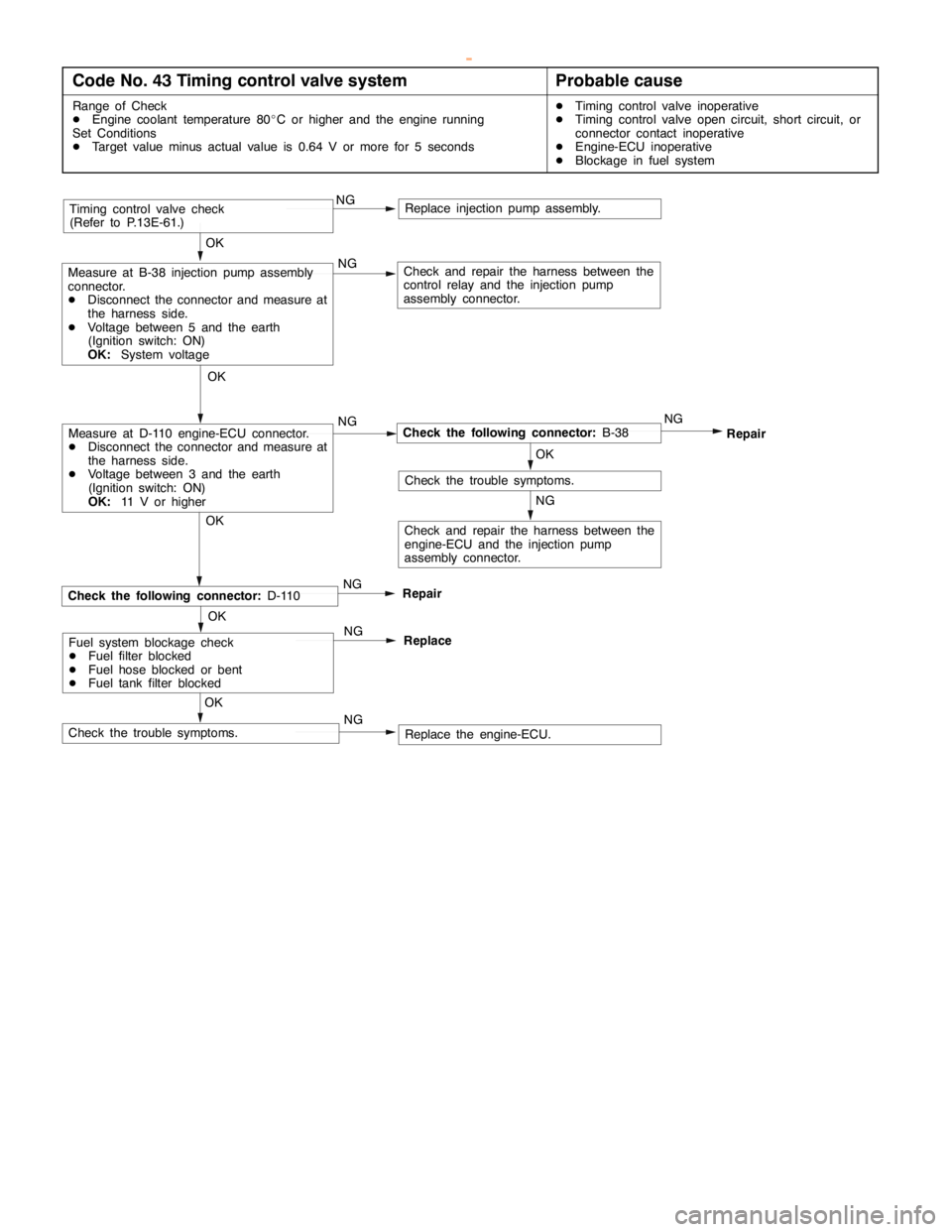
Code No. 43 Timing control valve systemProbable cause
Range of Check
DEngine coolant temperature 80_C or higher and the engine running
Set Conditions
DTarget value minus actual value is 0.64 V or more for 5 secondsDTiming control valve inoperative
DTiming control valve open circuit, short circuit, or
connector contact inoperative
DEngine-ECU inoperative
DBlockage in fuel system
OK
OK
Check and repair the harness between the
control relay and the injection pump
assembly connector.
Timing control valve check
(Refer to P.13E-61.)
Replace the engine-ECU. OK
RepairCheck the following connector:D-110
Check the trouble symptoms.NG NG NG
Check the following connector:B-38NG
Repair
OK
Check the trouble symptoms.
NG
NGMeasure at D-110 engine-ECU connector.
DDisconnect the connector and measure at
the harness side.
DVoltage between 3 and the earth
(Ignition switch: ON)
OK:11 V or higherOK
Measure at B-38 injection pump assembly
connector.
DDisconnect the connector and measure at
the harness side.
DVoltage between 5 and the earth
(Ignition switch: ON)
OK:System voltage
Replace injection pump assembly.
Check and repair the harness between the
engine-ECU and the injection pump
assembly connector.
Fuel system blockage check
DFuel filter blocked
DFuel hose blocked or bent
DFuel tank filter blockedOK
Replace NG
NG
www.WorkshopManuals.co.uk
Purchased from www.WorkshopManuals.co.uk
Page 639 of 1839

DIESEL FUEL <4D5-stepIII>-Troubleshooting13E-29
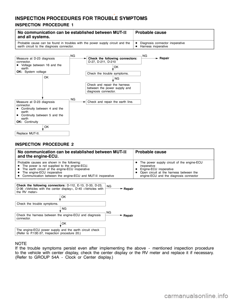
INSPECTION PROCEDURES FOR TROUBLE SYMPTOMS
INSPECTION PROCEDURE 1
No communication can be established between MUT-II
and all systems.
Probable cause
Probable cause can be found in troubles with the power supply circuit and the
earth circuit to the diagnosis connector.DDiagnosis connector inoperative
DHarness inoperative
OK
Check and repair the earth line.
OK
Replace MUT-II.
NG
Check and repair the harness
between the power supply and
diagnosis connector.
OK
Check the trouble symptoms.NG
Repair
NGCheck the following connectors:
D-27, D-211, D-210
NGMeasure at D-23 diagnosis
connector.
DVoltage between 16 and the
earth
OK:System voltage
Measure at D-23 diagnosis
connector.
DContinuity between 4 and the
earth
DContinuity between 5 and the
earth
OK:Continuity
INSPECTION PROCEDURE 2
No communication can be established between MUT-II
and the engine-ECU.
Probable cause
Probable causes are shown in the following:
DThe power is not supplied to the engine-ECU.
DThe earth circuit of the engine-ECU inoperative
DThe engine-ECU inoperative
DCommunication between the engine-ECU and MUT-IIinoperativeDThe power supply circuit of the engine-ECU
inoperative
DEngine-ECU inoperative
DOpen circuit at the harness between the
engine-ECU and the diagnosis connector
NG
Check the harness between the engine-ECU and diagnosis
connector.NGRepair
OK
Check the trouble symptoms.
Check the following connectors:D-112, E-13, D-33, D-23,
D-06
Repair
OK
The engine-ECU power supply and the earth circuit check
(Refer to P.13E-37, Inspection procedure 20.)
NOTE
If the trouble symptoms persist even after implementing the above - mentioned inspection procedure
to the vehicle with center display, check the center display or the RV meter and replace it if necessary.
(Refer to GROUP 54A - Clock or Center display.)
www.WorkshopManuals.co.uk
Purchased from www.WorkshopManuals.co.uk