2000 MITSUBISHI MONTERO lock
[x] Cancel search: lockPage 655 of 1839

DIESEL FUEL <4D5-stepIII>-Troubleshooting13E-45
Item
No.Reference
page Code No.
or inspec-
tion proce-
dure No. Value to be determined
as normal Inspection
conditions Drive Con-
tents Check item
27Fuel cut solenoid
valveTurn the
solenoid
valve from
OFF to ON or
from ON to
OFF.DIgnition
switch: ON
DVehicle
speed:
0 km/hMakes an audible
sound––
34Middle position
of GE actuatorHold the
injection
governor in
its middle
position.DIgnition
switch: ONWhen the crankshaft
is turned clockwise
during the adjustment
of the injection timing,
the injection pipes
spray out fuel.Code No.
4813E-23
35Variable
geometry
solenoid valveTurn the
solenoid
valve to ONIgnition switch:
ONMakes an audible
soundCode No.
4913E-24
36Turn the
solenoid
valve to OFFEngine: IdlingOperating sound and
vibration, which
accompany with the
duty activation, cease.
37EGR control
solenoid valve
No. 1Turn the
solenoid
valve from
OFF to ON
from ON to
OFFIgnition switch:
ONMakes an audible
soundProcedure
No. 2213E-38
38EGR control
solenoid valve
No. 2Turn the
solenoid
valve from
OFF to ON
from ON to
OFFIgnition switch:
ONMakes an audible
soundProcedure
No. 2313E-38
www.WorkshopManuals.co.uk
Purchased from www.WorkshopManuals.co.uk
Page 658 of 1839

DIESEL FUEL <4D5-stepIII>-Troubleshooting13E-48
Terminal
No.Normal condition: Inspection conditions (engine status) Check item
88Boost air temperature
sensorIgnition switch: ONIntake air temperature:
0_C3.2 - 3.8 V
Intake air temperature:
20_C2.3 - 2.9 V
Intake air temperature:
40_C1.4 - 2.0 V
Intake air temperature:
80_C0.4 - 1.0 V
89Crank angle sensorEngine: Idling (Use a digital voltage meter to check.)0V↔5V
(repeat the change)
90EGR valve position
sensor
Engine: After warm-
inguptheengine
Idling under no load2.3 - 3.3 V
sensoring up the engineEngine is suddenly racedMomentarily drops from
voltage during idling
91Parking switchIgnition switch: ON
(Enginestops)
Parking brake: ON0-1V
(Engine stops)Parking brake: OFFSystem voltage
CHECK CHART FOR RESISTANCE AND CONTINUITY
BETWEEN TERMINALS
1. Turn the ignition switch to LOCK (OFF) position.
2. Disconnect the engine-ECU connector.
3. Measure the resistance and check for continuity between
the terminals of the engine-ECU harness-side connector
while referring to the check chart.
NOTE
(1) When measuring resistance and checking continuity,
a harness for checking contact pin pressure should
be used instead of inserting a test probe.
(2) Checking need not be carried out in the order given
in the chart.
Caution
If the terminals that should be checked are mistaken,
or if connector terminals are not correctly shorted
to earth, damage may be caused to the vehicle wiring,
sensors, engine-ECU and/or ohmmeter.
Be careful to prevent this!
4. If the ohmmeter shows any deviation from the standard
value, check the corresponding sensor, actuator and
related electrical wiring, and then repair or replace.
5. After repair or replacement, recheck with the ohmmeter
to confirm that the repair or replacement has corrected
the problem.
www.WorkshopManuals.co.uk
Purchased from www.WorkshopManuals.co.uk
Page 679 of 1839

ENGINE COOLING -General Information/
Service Specifications/Lubricant/Sealant14-2
GENERAL INFORMATION
The cooling system is designed to keep every part
of the engine at appropriate temperature in
whatever condition the engine may be operated.
The cooling method is of the water-cooled, pressure
forced circulation type in which the water pump
pressurizes coolant and circulates it throughout the
engine. If the coolant temperature exceeds the
prescribed temperature, the thermostat opens to
circulate the coolant through the radiator as well
so that the heat absorbed by the coolant may be
radiated into the air.The water pump is of the centrifugal type and is
driven by the drive belt from the crankshaft.
The radiator is the corrugated fin, down flow type.
ItemsSpecifications
RadiatorPerformance kJ/h6G7203,023
4D5, 4M4232,326
SERVICE SPECIFICATIONS
ItemsStandard valueLimit
High pressure valve opening pressure of radiator cap kPa74 - 10364
Range of coolant antifreeze concentration of radiator %30 - 60-
ThermostatValve opening temper-6G788±
2.0-
ature of thermostat_
C4D582±
1.5-
4M476.5±
2.0-
Full-opening tempera-6G7100-
ture of thermostat_
C4D595-
4M490-
Valve lift mm6G710 or more-
4D5, 4M48.5 or more-
LUBRICANT
ItemApplicable modelAmount (including
condense tank) L
MITSUBISHI GENUINE COOLANT or equivalentVehicles without rear heater9.0
Vehicles with rear heater10.5
SEALANT
ItemsSpecified sealantRemarks
Cylinder block drain plug3M Nut Locking Part No. 4171 or equivalentDrying sealant
www.WorkshopManuals.co.uk
Purchased from www.WorkshopManuals.co.uk
Page 708 of 1839

S
ER VIC E SPEC IF IC ATIO NS
I te m s S
ta ndard va lu e L
im it W
aste gate actu ato r activ a tio n 4
D 5 A
ppro x. 9 2 -
p
re ssu re kP a 4
M 4 A
ppro x. 1 61 -
M
anif o ld dis to rtio n of th e in sta lla tio n su rfa ce m m 0
.1 5 or le ss 0
.2 0 S
pecif ie d se ala nt R
em ark s T
hre ad of th e in ta ke manif o ld mountin g
b olt s 3
M Stu d Lockin g No.4 170 or equiv a le nt A
naero bic se ala nt N
um ber N
am e U
se M
D998770 O
xyg en se nso r
w re nch R
em ova l/ In sta lla tio n ofo xyg en se nso r <6G 7>
Page 735 of 1839

INTAKE AND EXHAUST -General Information/Service Specifications/Sealant15-3
At starting and driving at low speed, the duty control
value of the variable geometry solenoid valve is
increased to apply the vacuum pressure of the
vacuum pump to the variable geometry actuator.
Applying the vacuum pressure to the variable
geometry actuator pulls the actuator rod so that
it can move towards the direction of closing the
variable nozzle of the variable geometry
turbocharger. As closing the nozzle reduces the
exhaust gas mass, the speed of exhaust gas flow
will be increased and efficiency will be improved.
Since the characteristic of boost pressure becomes
a low speed type, boost pressure will suddenly
rise from low speed.
At driving at high speed, the duty control value
of the variable geometry solenoid valve is
decreased to reduce the vacuum pressure from
the vacuum pump so that the actuator rod can
return to the deactivated status and move towards
the direction of opening the nozzle of the variable
geometry turbocharger.Opening the nozzle allows the characteristic of
boost pressure to become a high speed type so
that the appropriate boost pressure can be
maintained.
Therefore, boost pressure can be controlled by
appropriate duty control of the variable geometry
solenoid valve. The engine-ECU calculates the
correct boost pressure based on the engine speed
and fuel injection amount. Furthermore, the duty
control of the variable geometry solenoid valve is
given feedback of the signals from the variable
geometry control pressure sensor and the boost
pressure sensor so that the variable nozzle opening
angle of the variable geometry turbocharger can
be quickly adjusted to obtain the desired boost
pressure.
SERVICE SPECIFICATIONS
ItemsStandard value
Variable geometry actuator activation vacuum
(Approximately 1 mm stroke) kPaApproximately 10.5 - 12.5
Variable geometry solenoid valve coil resistance
(at 20°C)Ω29 - 35
SEALANT
ItemSpecified sealantRemarks
Thread of the intake manifold mounting
bolts3M Stud Locking No.4170 or equivalentAnaerobic sealant
www.WorkshopManuals.co.uk
Purchased from www.WorkshopManuals.co.uk
Page 821 of 1839

ENGINE AND EMISSION CONTROL -Auto-cruise Control System17-19
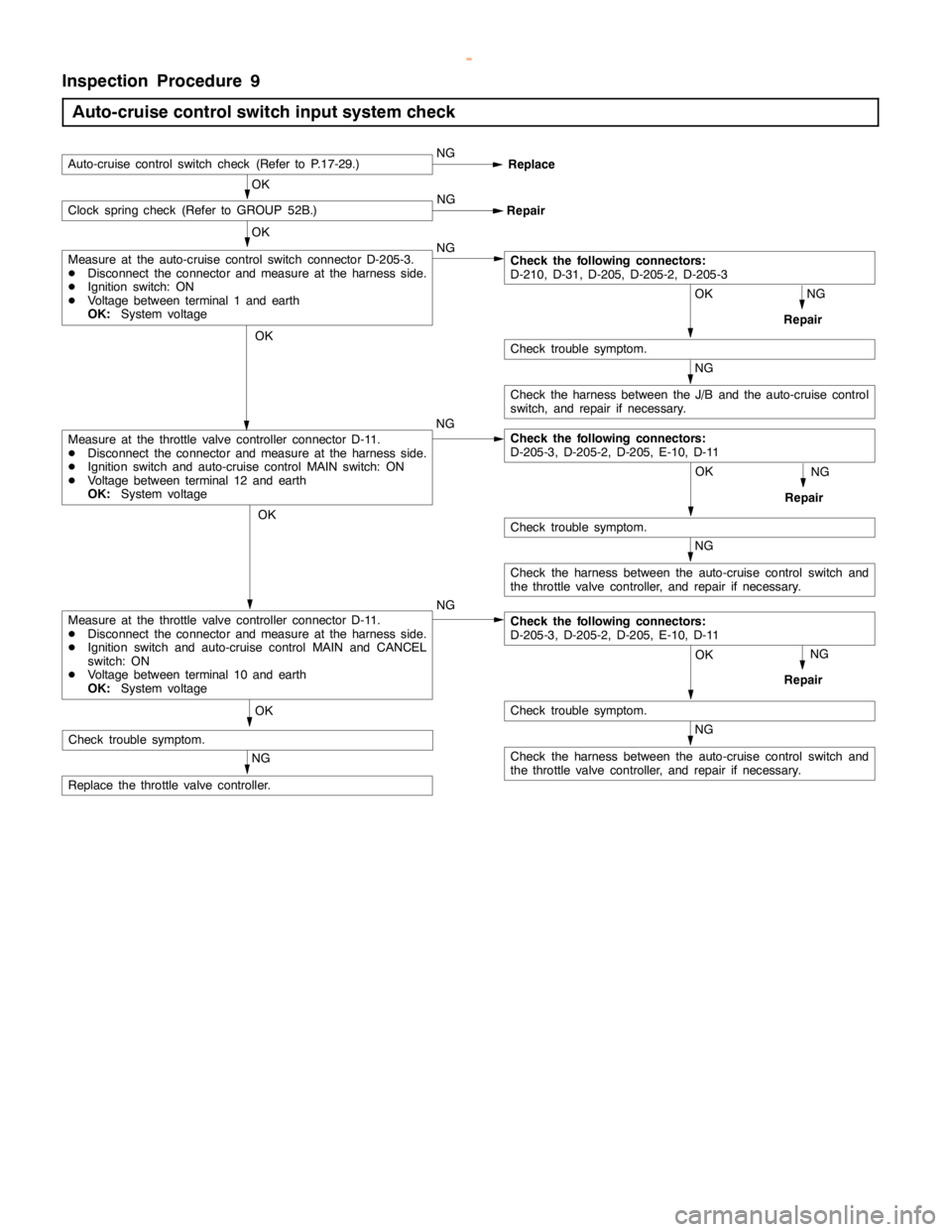
Inspection Procedure 9
Auto-cruise control switch input system check
NG
Check the harness between the auto-cruise control switch and
the throttle valve controller, and repair if necessary.
OK
NG
Repair
OK
Check trouble symptom. NG
OK
Auto-cruise control switch check (Refer to P.17-29.)NG
Replace
NG OKClock spring check (Refer to GROUP 52B.)
Repair
OK
NG
Repair
NG
OK
Check trouble symptom.
NG
Check the harness between the J/B and the auto-cruise control
switch, and repair if necessary.
Check the following connectors:
D-210, D-31, D-205, D-205-2, D-205-3
OK
Check trouble symptom.
NG
Repair
NG
Replace the throttle valve controller.NG
Measure at the throttle valve controller connector D-11.
DDisconnect the connector and measure at the harness side.
DIgnition switch and auto-cruise control MAIN switch: ON
DVoltage between terminal 12 and earth
OK:System voltage
Measure at the auto-cruise control switch connector D-205-3.
DDisconnect the connector and measure at the harness side.
DIgnition switch: ON
DVoltage between terminal 1 and earth
OK:System voltage
NG
Check the harness between the auto-cruise control switch and
the throttle valve controller, and repair if necessary.
OK
Check trouble symptom.
Check the following connectors:
D-205-3, D-205-2, D-205, E-10, D-11
Measure at the throttle valve controller connector D-11.
DDisconnect the connector and measure at the harness side.
DIgnition switch and auto-cruise control MAIN and CANCEL
switch: ON
DVoltage between terminal 10 and earth
OK:System voltageCheck the following connectors:
D-205-3, D-205-2, D-205, E-10, D-11
www.WorkshopManuals.co.uk
Purchased from www.WorkshopManuals.co.uk
Page 826 of 1839

ENGINE AND EMISSION CONTROL -Auto-cruise Control System17-24
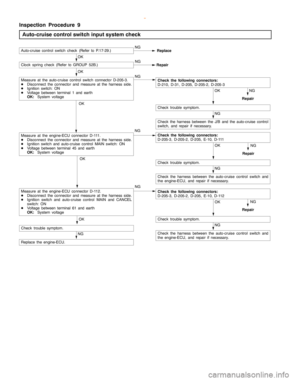
Inspection Procedure 9
Auto-cruise control switch input system check
NG
Check the harness between the auto-cruise control switch and
the engine-ECU, and repair if necessary.
OK
NG
Repair
OK
Check trouble symptom. NG
OK
Auto-cruise control switch check (Refer to P.17-29.)NG
Replace
NG OKClock spring check (Refer to GROUP 52B.)
Repair
OK
NG
Repair
NG
OK
Check trouble symptom.
NG
Check the harness between the J/B and the auto-cruise control
switch, and repair if necessary.
Check the following connectors:
D-210, D-31, D-205, D-205-2, D-205-3
OK
Check trouble symptom.
NG
Repair
NG
Replace the engine-ECU.NG
Measure at the engine-ECU connector D-111.
DDisconnect the connector and measure at the harness side.
DIgnition switch and auto-cruise control MAIN switch: ON
DVoltage between terminal 45 and earth
OK:System voltage
Measure at the auto-cruise control switch connector D-205-3.
DDisconnect the connector and measure at the harness side.
DIgnition switch: ON
DVoltage between terminal 1 and earth
OK:System voltage
NG
Check the harness between the auto-cruise control switch and
the engine-ECU, and repair if necessary.
OK
Check trouble symptom.
Check the following connectors:
D-205-3, D-205-2, D-205, E-10, D-111
Measure at the engine-ECU connector D-112.
DDisconnect the connector and measure at the harness side.
DIgnition switch and auto-cruise control MAIN and CANCEL
switch: ON
DVoltage between terminal 61 and earth
OK:System voltageCheck the following connectors:
D-205-3, D-205-2, D-205, E-10, D-112
www.WorkshopManuals.co.uk
Purchased from www.WorkshopManuals.co.uk
Page 847 of 1839

N
am e S
pecif ic a tio n E
xh aust em is sio n
c o ntr o l syste m E
xh aust g as re cir c u la tio n syste m
D EG R va lv e
D EG R so le noid va lv e No.1
D EG R so le noid va lv e No.2 E
le ctr o nic a lly -c o ntr o lle d EG R syste m
S in gle ty p e
D uty cycle so le noid va lv e
O N-O FF so le noid va lv e S
ta ndard va lu e E
G R so le noid va lv e Nos. 1 and 2re sis ta nce (a t 20_C ) W L
eve r posit io n se nso r outp utvo lt a ge V I
d le posit io n 0
.8 -1.0 F
ully open 3
.7 -4.9 E
ngin e sp eed se nso r re sis ta nce kW E
ngin e co ola ntte m pera tu re se nso r re sis ta nce A
t0_C 7
.7 -9.5 (
B uilt - in engin e co ola nt te m pera tu re gauge
u nit ) kW 2
.9 -3.6 A
t40_C 1
.3 -1.7 A
t80_C 0
.2 6 -0.3 5 S
pecif ie d se ala nt R
em ark E
ngin e co ola ntte m pera tu re gauge unit
t h re aded portio n 3
M Nut Lockin g Part N o. 4171 or equiv a le nt D
ry in g se ala nt N
um ber N
am e U
se M
D998464 T
e st harn ess
( 4 P, sq uare ) I
n sp ectio n of le ve r posit io n se nso r