2000 MITSUBISHI MONTERO lock
[x] Cancel search: lockPage 1632 of 1839
CHASSIS ELECTRICAL -Clock or Center Display54A-62
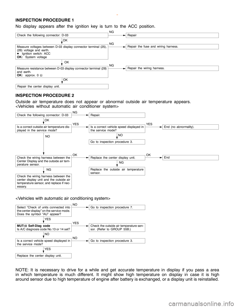
INSPECTION PROCEDURE 1
No display appears after the ignition key is turn to the ACC position.
OK
Measure voltages between D-03 display connector terminal (25),
(26) voltage and earth.
DIgnition switch: ACC
OK:System voltageNGRepair the fuse and wiring harness.
OK
Measure resistance between D-03 display connector terminal (28)
and earth.
OK:approx. 0
WNGRepair the wiring harness.
OK
Repair the center display unit.
Check the following connector: D-03NGRepair
INSPECTION PROCEDURE 2
Outside air temperature does not appear or abnormal outside air temperature appears.
Check the following connector: D-03NGRepair.
NO
Go to inspection procedure 3.
Check the wiring harness between the
Center Display and the outside air tem-
perature sensor.OKReplace the center display unit.OKEnd
NG
Replace the outside air temperature
sensor.NG
Check the wiring harness between the
center display unit and the outside air
temperature sensor, and replace if nec-
essary.
OK
Is a correct outside air temperature dis-
played in the servicemode?YESIs a correct vehicle speed displayed in
the servicemode?YESEnd (no abnormality).
NO
Select “Check of units connected into
the center display” on the service mode.
Does the symbol “AU” appear?NOGo to inspection procedure 7.
YES
Replace the center display unit.
YES
MUT-
IISelf-Diag code
Is A/C diagnosis code No.13 or 14 set?YESCheck the outside air temperature sen-
sor. (Refer to GROUP 55B.)
NO
Is a correct vehicle speed displayed in
the servicemode?NOGo to inspection procedure 3.
NOTE: It is necessary to drive for a while and get accurate temperature in display if you pass a area
in which temperature is much different. It might show high temperature on display in case it is high
around sensor due to high temperature of engine after battery is exchanged, or a display unit is reinstalled.
www.WorkshopManuals.co.uk
Purchased from www.WorkshopManuals.co.uk
Page 1633 of 1839
CHASSIS ELECTRICAL -Clock or Center Display54A-63
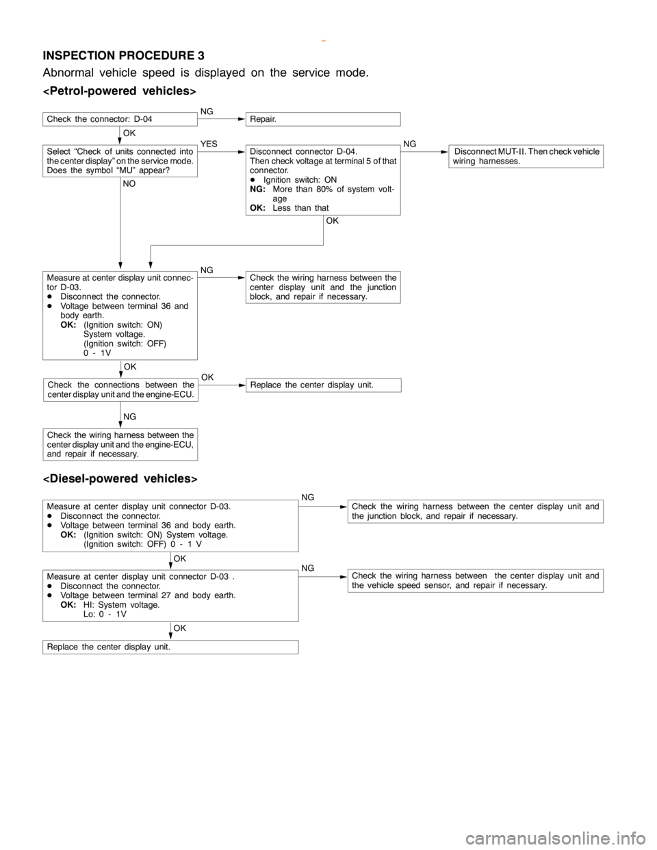
INSPECTION PROCEDURE 3
Abnormal vehicle speed is displayed on the service mode.
OK
NGRepair.
Measure at center display unit connec-
tor D-03.
DDisconnect the connector.
DVoltage between terminal 36 and
body earth.
OK:(Ignition switch: ON)
System voltage.
(Ignition switch: OFF)
0-1VNGCheck the wiring harness between the
center display unit and the junction
block, and repair if necessary.
NG
Check the wiring harness between the
center display unit and the engine-ECU,
and repair if necessary.
Select “Check of units connected into
the center display” on the service mode.
Does the symbol “MU” appear?YES NGDisconnect MUT-
II. Then check vehicle
wiring harnesses.Disconnect connector D-04.
Then check voltage at terminal 5 of that
connector.
DIgnition switch: ON
NG:More than 80% of system volt-
age
OK:Less than that
OK NO
OK
Check the connections between the
center display unit and the engine-ECU.OKReplace the center display unit.
Check the connector: D-04
Measure at center display unit connector D-03.
DDisconnect the connector.
DVoltage between terminal 36 and body earth.
OK:(Ignition switch: ON) System voltage.
(Ignition switch: OFF) 0 - 1 VNGCheck the wiring harness between the center display unit and
the junction block, and repair if necessary.
OK
Measure at center display unit connector D-03 .
DDisconnect the connector.
DVoltage between terminal 27 and body earth.
OK:HI: System voltage.
Lo: 0 - 1VNGCheck the wiring harness between the center display unit and
the vehicle speed sensor, and repair if necessary.
OK
Replace the center display unit.
www.WorkshopManuals.co.uk
Purchased from www.WorkshopManuals.co.uk
Page 1634 of 1839
CHASSIS ELECTRICAL -Clock or Center Display54A-64
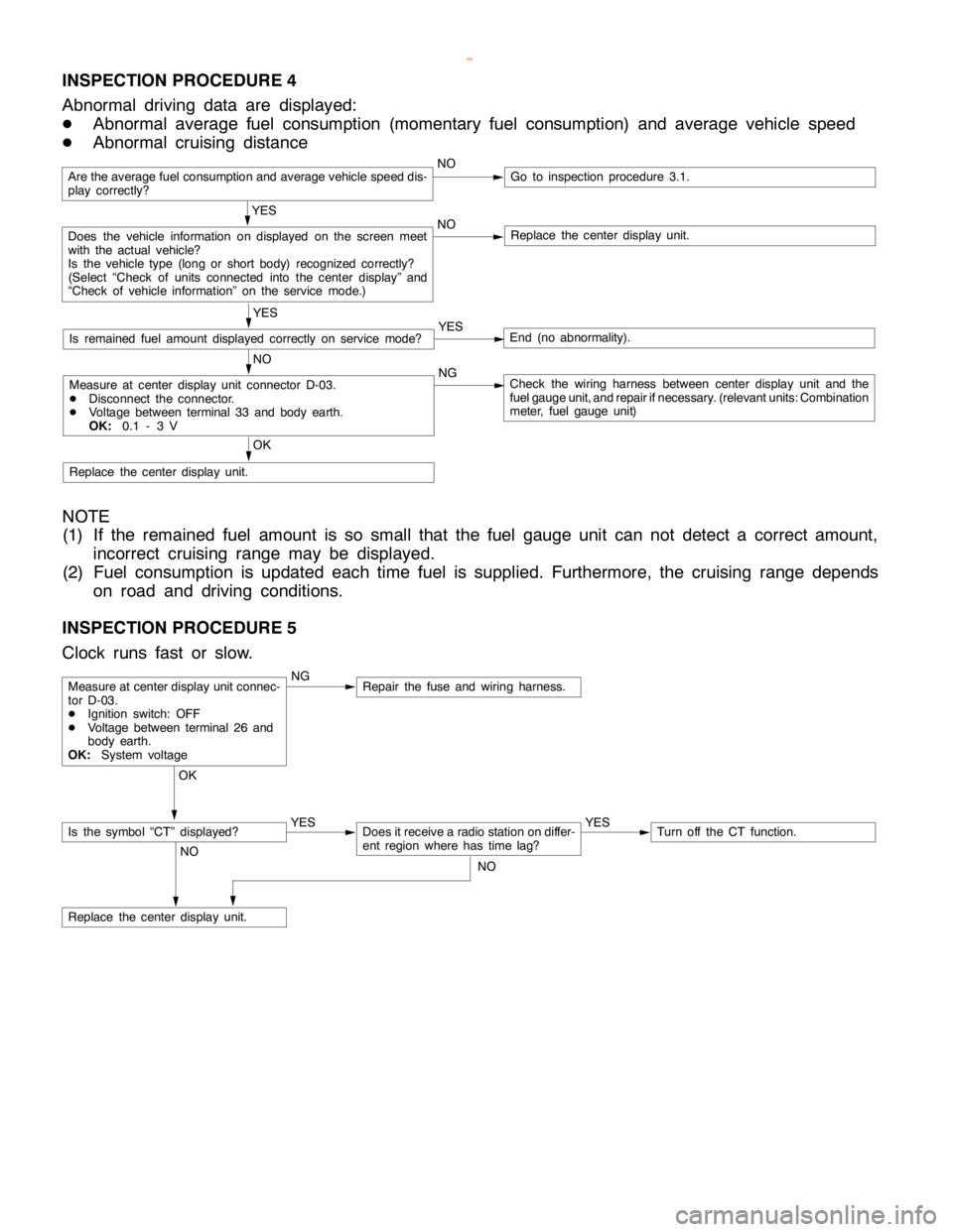
INSPECTION PROCEDURE 4
Abnormal driving data are displayed:
DAbnormal average fuel consumption (momentary fuel consumption) and average vehicle speed
DAbnormal cruising distance
Are the average fuel consumption and average vehicle speed dis-
play correctly?NOGo to inspection procedure 3.1.
YES
Does the vehicle information on displayed on the screen meet
with the actual vehicle?
Is the vehicle type (long or short body) recognized correctly?
(Select “Check of units connected into the center display” and
“Check of vehicle information” on the service mode.)NOReplace the center display unit.
YES
Is remained fuel amount displayed correctly on servicemode?YESEnd (no abnormality).
NO
Measure at center display unit connector D-03.
DDisconnect the connector.
DVoltage between terminal 33 and body earth.
OK:0.1 - 3 VNGCheck the wiring harness between center display unit and the
fuel gauge unit, and repair ifnecessary. (relevant units: Combination
meter, fuel gauge unit)
OK
Replace the center display unit.
NOTE
(1) If the remained fuel amount is so small that the fuel gauge unit can not detect a correct amount,
incorrect cruising range may be displayed.
(2) Fuel consumption is updated each time fuel is supplied. Furthermore, the cruising range depends
on road and driving conditions.
INSPECTION PROCEDURE 5
Clock runs fast or slow.
NGRepair the fuse and wiring harness.
OK
YES
Does it receive a radio station on differ-
ent region where has timelag?YESTurn off the CT function.
NO
Replace the center display unit.
Measure at center display unit connec-
tor D-03.
DIgnition switch: OFF
DVoltage between terminal 26 and
body earth.
OK:System voltage
Is the symbol “CT” displayed?
NO
www.WorkshopManuals.co.uk
Purchased from www.WorkshopManuals.co.uk
Page 1635 of 1839
CHASSIS ELECTRICAL -Clock or Center Display54A-65
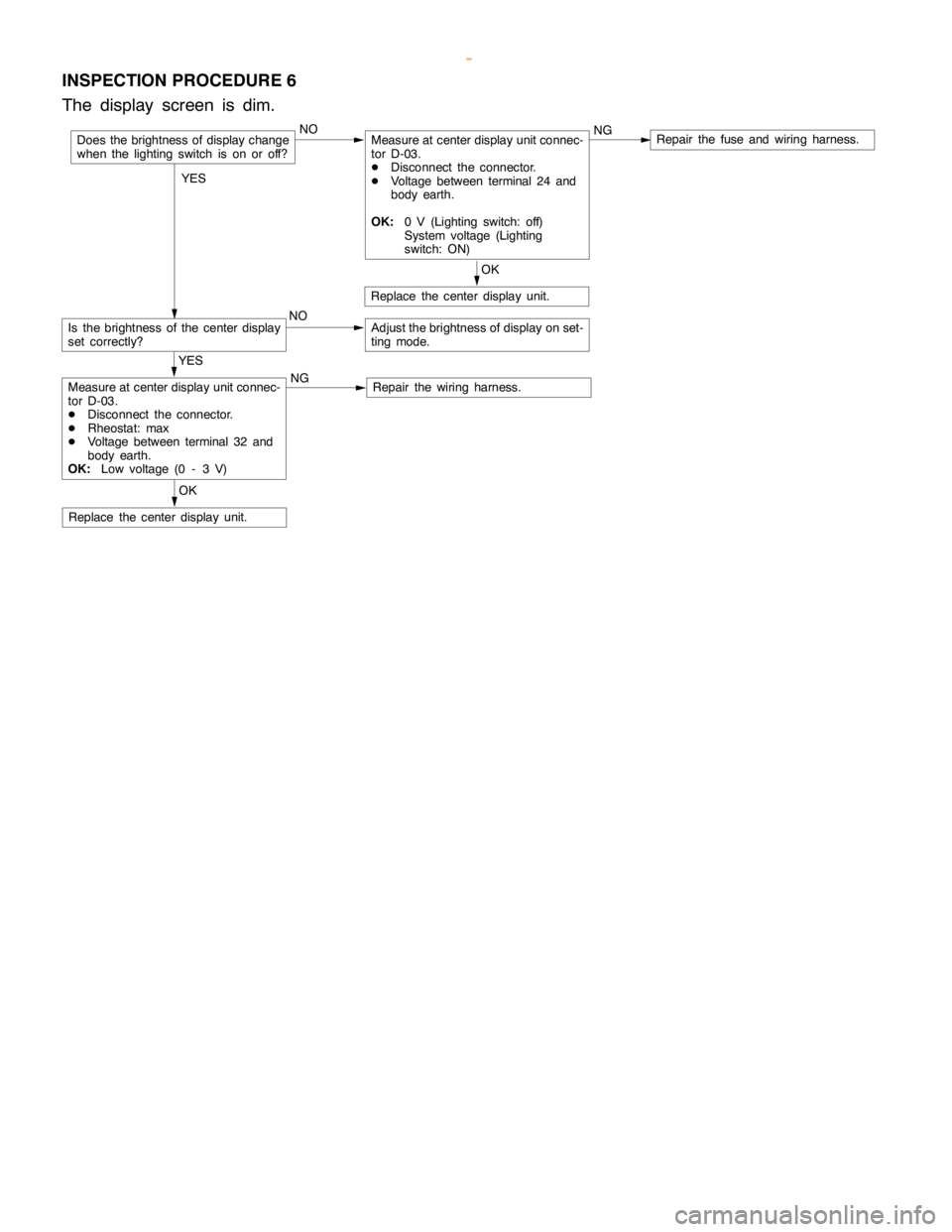
INSPECTION PROCEDURE 6
The display screen is dim.
NOMeasure at center display unit connec-
tor D-03.
DDisconnect the connector.
DVoltage between terminal 24 and
body earth.
OK:0 V (Lighting switch: off)
System voltage (Lighting
switch: ON)NGRepair the fuse and wiring harness.
Is the brightness of the center display
set correctly?NOAdjust the brightness of display on set-
ting mode.
OK
Replace the center display unit.
OK
Replace the center display unit.
YES
Measure at center display unit connec-
tor D-03.
DDisconnect the connector.
DRheostat: max
DVoltage between terminal 32 and
body earth.
OK:Low voltage (0 - 3 V)NGRepair the wiring harness.
Does the brightness of display change
when the lighting switch is on or off?
YES
www.WorkshopManuals.co.uk
Purchased from www.WorkshopManuals.co.uk
Page 1636 of 1839
CHASSIS ELECTRICAL -Clock or Center Display54A-66
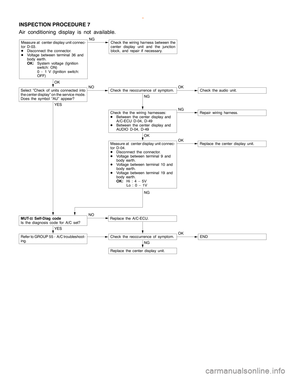
INSPECTION PROCEDURE 7
Air conditioning display is not available.
Measure at center display unit connec-
tor D-03.
DDisconnect the connector.
DVoltage between terminal 36 and
body earth.
OK:System voltage (Ignition
switch: ON)
0 - 1 V (Ignition switch:
OFF)NGCheck the wiring harness between the
center display unit and the junction
block, and repair if necessary.
OK
NO OK
Check theaudio unit.
NG
NG
Repair wiring harness.
OK
OK
Replace the center display unit.
YES
Replace the A/C-ECU.
YES
Refer to GROUP 55 - A/C troubleshoot-
ing.Check the reoccurrence of symptom.OKEND
NG
Replace the center display unit.
Measure at center display unit connec-
tor D-04.
DDisconnect the connector.
DVoltage between terminal 9 and
body earth.
DVoltage between terminal 10 and
body earth.
DVoltage between terminal 19 and
body earth.
OK:Hi:4–5V
Lo:0–1V
Check the the wiring harnesses:
DBetween the center display and
A/C-ECU D-04, D-49
DBetween the center display and
AUDIO D-04, D-49
Check the reoccurrence of symptom.Select “Check of units connected into
the center display” on the service mode.
Does the symbol “AU” appear?
MUT-
IISelf-Diag code
Is the diagnosis code for A/C set?NG
NO
www.WorkshopManuals.co.uk
Purchased from www.WorkshopManuals.co.uk
Page 1678 of 1839

CHASSIS ELECTRICAL -RV Meter54A-17
Termi-Input/out-
t
Signal sym-
bl
Terminal
lt
Harness problemTrouble symptoms when there is a
hblnal No.
p
put
gy
bolvoltage
(V)Open
circuitshort-cir-
cuit
yp
harness problem
11 - 1 4––––––
15Input/out-
putK (engine
K-LINE
signal)Hi: Sys-
tem volt-
age
Lo:0 - 1ExistsExistsDWiring communication error
DCommunication between the
engine-A/T-ECU
DAbnormal driving information
numerical display
16––––––
17Input/out-
putM-BUSY
(AUDIO)Hi:System
voltage
Lo:0 - 1ExistsExistsDAudio information does not
appear on the screen.
18–SHIELD-
EARTH
(AUDIO)––––
19Input/out-
putM-BUSY
(A/C)Hi:System
voltage
Lo:0 - 1ExistsExistsDAir conditioner information does
not appear on the screen.
DAmbient temperature is not
displayed.
20–SHIELD-
EARTH––––
22 - 21––––––
23InputAmbient
temperature
sensor–ExistsExistsDAmbient temperature is not
displayed.
24InputILL + (Light-
ing switch)Hi:System
voltage
Lo:0 - 1ExistsExistsDoes not illuminate.
25InputACC (ACC
power sup-
l)
System
voltageExists–Screen does not appear. No
operations are possible.
pp
ply)
g
–ExistsBlown multi-purpose fuse
26Input+BSystem
voltageExists–Screen does not appear. No
operations are possible.
g
–ExistsBlown multi-purpose fuse
27InputVSS (Vehicle
speed pulse
signal)Hi:System
voltage
Lo:0 - 1ExistsExistsDAbnormal “Distance km after
replacement” display in mainte-
nance screen
DSwitches which are not
supposed to operate during
driving do operate.
(Example:clock adjustment
screen, maintenance settings,
etc.)
DAmbient temperature display is
abnormally high.
28–Earth–Exists–Screen does not appear.
www.WorkshopManuals.co.uk
Purchased from www.WorkshopManuals.co.uk
Page 1688 of 1839
SWS -General InformationSWS -General Information54B-2
GENERAL INFORMATION
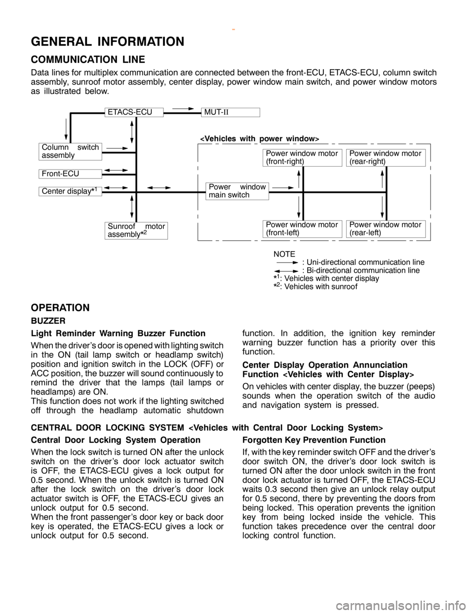
COMMUNICATION LINE
Data lines for multiplex communication are connected between the front-ECU, ETACS-ECU, column switch
assembly, sunroof motor assembly, center display, power window main switch, and power window motors
as illustrated below.
ETACS-ECUMUT-II
Column switch
assembly
Front-ECU
Power window
main switch
Power window motor
(front-right)
Center display*1
Sunroof motor
assembly*2Power window motor
(front-left)
Power window motor
(rear-right)
Power window motor
(rear-left)
NOTE
: Uni-directional communication line
: Bi-directional communication line
*
1: Vehicles with center display
*2: Vehicles with sunroof
OPERATION
BUZZER
Light Reminder Warning Buzzer Function
When the driver’s door is opened with lighting switch
in the ON (tail lamp switch or headlamp switch)
position and ignition switch in the LOCK (OFF) or
ACC position, the buzzer will sound continuously to
remind the driver that the lamps (tail lamps or
headlamps) are ON.
This function does not work if the lighting switched
off through the headlamp automatic shutdownfunction. In addition, the ignition key reminder
warning buzzer function has a priority over this
function.
Center Display Operation Annunciation
Function
On vehicles with center display, the buzzer (peeps)
sounds when the operation switch of the audio
and navigation system is pressed.
CENTRAL DOOR LOCKING SYSTEM
Central Door Locking System Operation
When the lock switch is turned ON after the unlock
switch on the driver’s door lock actuator switch
is OFF, the ETACS-ECU gives a lock output for
0.5 second. When the unlock switch is turned ON
after the lock switch on the driver’s door lock
actuator switch is OFF, the ETACS-ECU gives an
unlock output for 0.5 second.
When the front passenger’s door key or back door
key is operated, the ETACS-ECU gives a lock or
unlock output for 0.5 second.Forgotten Key Prevention Function
If, with the key reminder switch OFF and the driver’s
door switch ON, the driver’s door lock switch is
turned ON after the door unlock switch in the front
door lock actuator is turned OFF, the ETACS-ECU
waits 0.3 second then give an unlock relay output
for 0.5 second, there by preventing the doors from
being locked. This operation prevents the ignition
key from being locked inside the vehicle. This
function takes precedence over the central door
locking control function.
www.WorkshopManuals.co.uk
Purchased from www.WorkshopManuals.co.uk
Page 1689 of 1839

SWS -General Information54B-3
POWER WINDOWS
Power Windows Operation
A signal line dedicated for transmission of multiplex
communication data is connected between the
power window main switches and the power window
motor-ECU.
Communication is uni-directional. The power
window main switches have a transmitting circuit
only, whereas the power window sub switches have
a receiving circuit only.
Power Window Timer Function
With the ignition switch in the ON position, the power
window relay and power window switch receipt
permission signal (a SWS signal transmitted from
the ETACS-ECU) are turned ON [the power windowswitch receipt permission signal remains ON for 30
seconds after the ignition switch is turned LOCK
(OFF)], enabling opening and closing of the
windows. The power window relay goes ON for
additional 30 seconds. If the driver’s door is
subsequently closed during this period, the receipt
permission signal goes OFF. The power window
relay goes OFF 10 seconds after the receipt
permission signal goes OFF.
If the driver’s door is opened during timer operation,
the receipt permission signal goes ON for additional
30 seconds. If the driver’s door is subsequently
closed during this period, the receipt permission
signal goes OFF ten seconds after the receipt
permission signal goes OFF.
KEYLESS ENTRY SYSTEM
Keyless Entry System Operation
If the transmitter LOCK or UNLOCK switch is
pressed while the ignition key is removed and all
of the doors are closed, the doors can be locked
or unlocked.
Keyless Entry Answerback Function
The keyless entry hazard answerable function
facilitates confirmation of door locking and unlock-
ing operations even in daylight. When a LOCKsignal from the keyless entry transmitter is applied
to the ETACS-ECU, all of the turn-signal lamps flash
twice. When an UNLOCK signal from the keyless
entry transmitter is applied to the ETACS-ECU, all of
the turn-signal lamps flash four times. Note that an
unlock switch has change from OFF to ON.
NOTE
The hazard answer back is enabled or disabled
by the configuration function.
SUNROOF
Sunroof Operation
All of the slide open/close, tilt up/down, and stop
operations can be performed by a single switch.
When the roof lid glass is tilted up, the sunshade
opens approximately 98 mm in combined operation
with the roof lid glass for better ventilation.
A jam preventing mechanism has been adopted.
When a slide-close or tilt-down operation is blocked
by an external force, the roof lid glass moves back
and stops.Sunroof Timer Function
When the ignition switch is turned from ON position
to LOCK (OFF) or ACC position, the sunroof will
be ready to work for 30 seconds.
If the driver’s door is opened during the timer
operation, the timer operates for another
30
seconds starting from that point. However, the
timer operation discontinues if the door is closed
during that period.
www.WorkshopManuals.co.uk
Purchased from www.WorkshopManuals.co.uk