Page 65 of 280

SEATS AND SEATBELTS
3–37
WARNING
If any of the following conditions
occur, the SRS is not working proper-
ly and you should immediately have it
inspected by an authorized MITSUBI-
SHI dealer.
The SRS warning lamp does not
illuminate when you start the ve-
hicle.
The SRS warning lamp does not
go out after several seconds.
The SRS warning lamp illumi-
nates while driving.
SRS servicingEG29G-A
The entire SRS including air bag and pre-
tensioner seat belt must be inspected by an
authorized MITSUBISHI dealer after
10 years.
WARNING
(1) Any maintenance performed on
or near the components of the
SRS must be performed only by
an authorized MITSUBISHI
dealer. Do not permit anyone else
to do service, inspection, main-
tenance or repair on any SRS
components or wiring; similarly,
no part of the SRS should ever be
handled or disposed of by any-
one except an authorized MITSU-
BISHI dealer.
Improper work on the SRS com-
ponents or wiring could result in
inadvertent deployment of the air
bags or could render the SRS in-
operative; either situation could
result in serious injury.
WARNING
(2) Do not modify your steering
wheel, seat belt retractor or any
other SRS components. For
example, replacement of the
steering wheel or modifications
to the front bumper or body struc-
ture can adversely affect SRS
performance and lead to possible
injury.
(3) If your vehicle has received any
front-end damage, you should
have the SRS inspected by an
authorized MITSUBISHI dealer to
ensure it is in proper working
order.
(4) On vehicles with the side air
bags, do not modify your front
seats, centre pillar and centre
console.
It can adversely affect SRS per-
formance and lead to possible in-
jury.
Also, if you have found any tear or
open seam in the seat fabric at the
portion near the side air bag, have
the seat inspected at an author-
ized MITSUBISHI dealer.
Page 66 of 280
SEATS AND SEATBELTS
3–38
WARNING
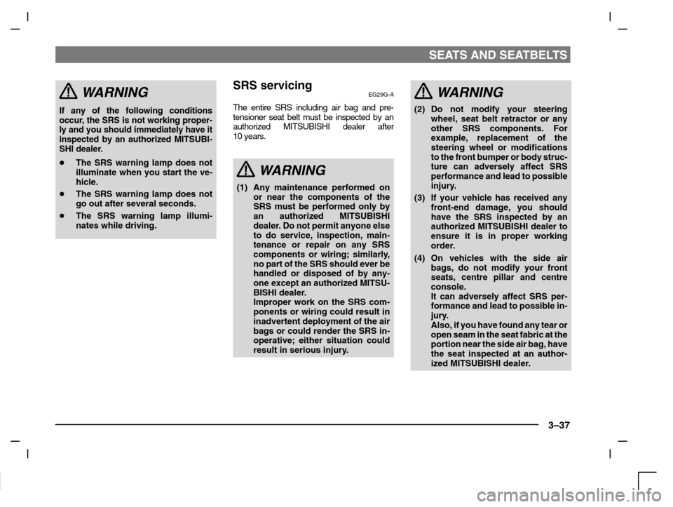
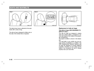
(5) On vehicles with side air bags, if
your vehicle has received any
damage to either side, you should
have the SRS inspected by an
authorized MITSUBISHI dealer to
ensure it is in proper working
order.
NOTE
(1) When you transfer ownership of the ve-
hicle to some other person, we urge you
to alert the new owner that it is equipped
with the SRS and refer that owner to the
applicable section in this owner’s man-
ual.
(2) If you junk or scrap the vehicle, we urge
you to first take the vehicle to an author-
ized MITSUBISHI dealer so that the
SRS can be rendered safe.
G28G062a
Caution labelEG29H-Aa
Passenger restraint warning/caution labels
are attached as shown in the illustration.
Page 67 of 280

Instruments and controls
Instruments 4–2. . . . . . . . . . . . . . . . . . . . . . . . . . . . . .
Speedometer 4–2. . . . . . . . . . . . . . . . . . . . . . . . . . . . .
Odometer/Tripmeter 4–3. . . . . . . . . . . . . . . . . . . . . . .
Tachometer 4–4. . . . . . . . . . . . . . . . . . . . . . . . . . . . . . .
Fuel gauge 4–4. . . . . . . . . . . . . . . . . . . . . . . . . . . . . . .
Water temperature gauge 4–5. . . . . . . . . . . . . . . . . .
Indication and warning lamps 4–6. . . . . . . . . . . . . .
Combination headlamps, dipper and turn
signal switch 4–12. . . . . . . . . . . . . . . . . . . . . . . . . . . .
Headlamp levelling switch 4–13. . . . . . . . . . . . . . . . .
Windscreen wiper and washer switch 4–15. . . . . .
Rear window wiper and washer switch
(Hatchback) 4–16. . . . . . . . . . . . . . . . . . . . . . . . . . . . .
Headlamp washer switch* 4–17. . . . . . . . . . . . . . . . .
Hazard warning flasher switch 4–18. . . . . . . . . . . . .
Rear window demister switch 4–19. . . . . . . . . . . . .
Front fog lamp switch* 4–20. . . . . . . . . . . . . . . . . . . .
Rear fog lamp switch 4–21. . . . . . . . . . . . . . . . . . . . .
Rheostat
(meter illumination control) 4–21. . . . . . . . . . . . . . . .
Horn switch 4–22. . . . . . . . . . . . . . . . . . . . . . . . . . . . .
Room lamps 4–22. . . . . . . . . . . . . . . . . . . . . . . . . . . . .
Multi centre display 4–24. . . . . . . . . . . . . . . . . . . . . .
Digital clock 4–26. . . . . . . . . . . . . . . . . . . . . . . . . . . . .
Page 68 of 280
INSTRUMENTS AND CONTROLS
4–2
Type 1
D01A231a
InstrumentsED01AMKb
1-Fuel gauge
2-Speedometer
3-Tachometer*
4-Water temperature gauge
5-Tripmeter reset button
6-Tripmeter
7-Odometer
Type 2
D01A232a
Type 1
D03A082a
SpeedometerED03A-Ca
Type 1The speedometer indicates the vehicle’s
speed in kilometres per hour (km/h).
Page 69 of 280

INSTRUMENTS AND CONTROLS
4–3
Type 2
D03A083a
Type 2The speedometer indicates the vehicle’s
speed in miles per hour (mph) and kilo-
metres per hour (km/h).
D03F036a
Odometer/TripmeterED03FANb
When the ignition switch is turned “ON”, the
odometer display is given in the lower dis-
play window (1). The upper display window
(2) shows the tripmeter A and tripmeter B
distances in that sequence. It then shows
the distance that was displayed before the
ignition switch was last turned to the “OFF”.
Every time the reset button (3) is pressed
lightly (less than one second), the upper dis-
play is changed as below.
D03F055a
OdometerThe odometer indicates the total distance
the vehicle has travelled.
TripmeterThere are two tripmeters: A and B. These
indicate the distance travelled during a par-
ticular trip or period.
4– Tripmeter A indicates the distance tra-
velled since the current trip begins.
5– Tripmeter B indicates the distance from
an intermediate location.
To r e t u r n the indication to 0, press the
reset button for more than 1 second.
Only the currently displayed value will
be reset.
Page 70 of 280
INSTRUMENTS AND CONTROLS
4–4
NOTE
(1) Display A and B each have a maximum
distance of 999.9 mile (km).
(2) When disconnecting the battery ter-
minal for a long time, the memory of trip-
meter display A and B are cleared, and
the display returns to “0”.
D04A067a
TachometerED04A-Ac
The tachometer indicates the engine speed
(r/min). The tachometer can help you obtain
more economical driving and also warns you
of excessive engine speeds.
CAUTION
During travel, watch the tachometer
making sure that the engine speed in-
dication does not rise to the red zone
(excessive engine rpm).
Type 1
D05A020a
Fuel gaugeED15A-Ea
The fuel gauge indicates the fuel level in the
fuel tank irrespective of the ignition switch
position.
0- Empty
1- Full
CAUTION
Do not drive with an extremely low
fuel level; running out of fuel could
cause damage to the catalytic con-
verter.
Page 71 of 280
INSTRUMENTS AND CONTROLS
4–5
Type 2
D05A024a
NOTE(1) 
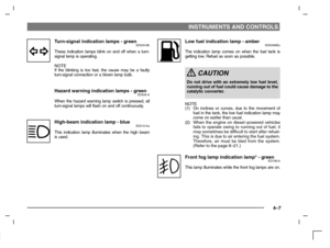
The fuel lid mark (A) indicates the side
where the fuel lid (fuel filler port) is lo-
cated on the vehicle.
Refer to “Fuel usage” on page 5–3.
(2) Just after refueling, it takes time for the
correct fuel level to be indicated after
switching on the ignition.
Type 1
D06A035a
Water temperature gaugeED06A - Ld
The water temperature gauge indicates the
engine coolant temperature when the igni-
tion switch is “ON”.
CAUTION
If the indication needle enters the
overheating zone while the engine is
running, it indicates that the engine is
possibly overheating. Immediately
park your vehicle in a safe place and
make the necessary corrections.
(Refer to “Engine overheating” on
page 8–15.)
While driving, care should always be
taken to maintain the normal operat-
ing temperature.
Type 2
D06A024a
Page 72 of 280

INSTRUMENTS AND CONTROLS
4–6
D50A532d
A: Petrol-powered vehicle
B: Diesel-powered vehicle
Indication and warning lampsED50AMFe1-Turn - signal indication lamps/Hazard warning lamps
2-Automatic transmission indication lamp
(vehicles with A/T only, “N” indicator lamp is used also as A/T
warning lamp.) Page 5–18
3-High - beam indication lamp
4-Low fuel warning lamp
5-Front fog lamp indication lamp*
6-Rear fog lamp indication lamp
7-Door ajar warning lamp
8-ABS warning lamp* Page 5–28
9-Brake warning lamp
10 -HOLD indication lamp (vehicle with automatic transmission IN-
VECS-II 4A/T only) Page 5–20
11-Supplemental restraint (SRS) warning lamp Page 3–36
12 -Oil pressure warning lamp13 -Charge warning lamp
14 -TCL indication lamp* Page 5–34
15 -Check engine indication lamp
16 -Cruise control indication lamp* Page 5–35
17 -Diesel preheat indication lamp
(diesel-powered vehicles only)
18 -Overheating warning lamp
(diesel-powered vehicles only)
NOTE
To find information concerning the indication or warning lamps
marked by the symbol “Page xx”, refer to the specified pages. For
the other indication and warning lamps, refer to the subsequent
pages.