2000 MITSUBISHI CARISMA weight
[x] Cancel search: weightPage 9 of 280

GENERAL INFORMATION
1–9
Modification / alterations to
the electric or fuel systems
EB11A-D
MITSUBISHI has always manufactured
safe, high quality vehicles. In order to main-
tain this safety and quality, it is important that
any accessory that is to be fitted, or any
modifications carried out which involve the
electric or fuel systems, should be carried
out in accordance with MITSUBISHI guide-
lines.
CAUTION
Please consult an authorized MITSU-
BISHI dealer concerning any such fit-
ment or modification.
If the wires interfere with the vehicle
body or improper installation
methods are used (protective fuses
not included, etc.), electronic devices
may be adversely affected, resulting
in a fire or other accident.
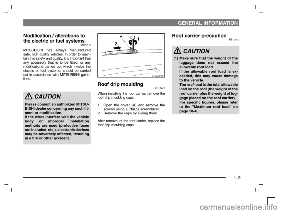
B10A001a
Roof drip mouldingEB10A-T
When installing the roof carrier, remove the
roof drip moulding caps.
1. Open the cover (A) and remove the
screws using a Philips screwdriver.
2. Remove the caps by sliding them.
After removal of the roof carrier, replace the
roof drip moulding caps.
Roof carrier precautionEB10A-U
CAUTION
(1) Make sure that the weight of the
luggage does not exceed the
allowable roof load.
If the allowable roof load is ex-
ceeded, this may cause damage
to the vehicle.
The roof load is the total allowable
load on the roof (the weight of the
roof carrier plus the weight of lug-
gage placed on the roof carrier).
For specific figures, please refer
to the ”Maximum roof load” on
page 10–6.
Page 10 of 280

GENERAL INFORMATION
1–10
CAUTION
(2) When luggage is loaded onto the
vehicle, please make sure to drive
slowly and avoid excessive man-
euvers such as sudden braking or
quick turning.
In addition, place the luggage on
the carrier so that its weight is dis-
tributed evenly with the heaviest
items on the bottom. Do not load
items that are wider than the roof
carrier.
The additional weight on the roof
could heighten the vehicle’s centre
of gravity and affect the vehicle
handling characteristics.
As a result, driving errors or emerg-
ency maneuvers could lead to a
loss of control and result in an acci-
dent.
CAUTION
(3) Before driving and after travelling a
short distance, always check the
load to make sure it is securely fas-
tened to the roof carrier.
Check periodically during your
travel that the load remains secure.
If the load is not secure, it could fall
from the vehicle and damage your
vehicle, another vehicle or create
road hazard.
NOTE
(1) To prevent wind noise or reduction in
gas mileage, remove the roof carrier
when not in use.
(2) Before using an automatic car wash,
check with the attendant to determine if
the roof carrier should be removed.
(3) Be sure that adequate clearance is
maintained for raising the sunroof (For
vehicles with sunroof) and tailgate
(hatchback) when installing a roof
carrier.
Genuine partsEB05A-Fi
Don’t play around with substitutes.
MITSUBISHI has gone to great lengths to
bring you a superbly crafted vehicle offering
the highest quality and dependability. Don’t
reduce that quality and dependability by us-
ing substitute parts.
Always use MITSUBISHI Genuine Parts de-
signed and manufactured to maintain your
MITSUBISHI vehicle at top performance.
The operation of vehicle components can be
less efficient in case of using Non-Genuine
Parts.
Failure to use Genuine Parts may invalidate
any future warranty claim. MITSUBISHI will
not be liable for any malfunction of your ve-
hicle that may have been caused by the use
of substitute parts in place of MITSUBISHI
Genuine Parts.
At the MITSUBISHI dealer you can also get
appropriate advice and the assembling of
Genuine Parts will be handled professional-
ly.
MITSUBISHI Genuine Parts are identified by
this mark and are available at all authorized
MITSUBISHI dealers.
Page 45 of 280

SEATS AND SEATBELTS
3–17
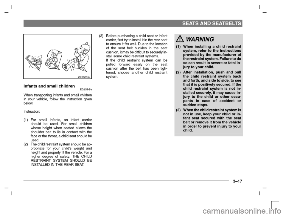
G28B005a
Infants and small childrenEG20B-Ba
When transporting infants and small children
in your vehicle, follow the instruction given
below.
Instruction:
(1) For small infants, an infant carrier
should be used. For small children
whose height when seated allows the
shoulder belt to lie in contact with the
face or the throat, a child seat should be
used.
(2) The child restraint system should be ap-
propriate for your child’s weight and
height and properly fit the vehicle. For a
higher degree of safety: THE CHILD
RESTRAINT SYSTEM SHOULD BE
INSTALLED IN THE REAR SEAT.(3) Before purchasing a child seat or infant
carrier, first try to install it in the rear seat
to ensure it fits well. Due to the location
of the seat belt buckles in the seat
cushion, it may be difficult to securely in-
stall some child restraint systems.
If the child restraint system can be
pulled forward easily on the seat
cushion after the belt has been tigh-
tened, choose another child restraint
system.
WARNING
(1) When installing a child restraint
system, refer to the instructions
provided by the manufacturer of
the restraint system. Failure to do
so can result in severe or fatal in-
jury to your child.
(2) After installation, push and pull
the child restraint system back
and forth, and side to side, to see
that it is positively secured. If the
child restraint system is not in-
stalled securely, it may cause in-
jury to the child or other occu-
pants in case of accident or
sudden stops.
(3) When the child restraint system is
not in use, keep your child or in-
fant seat secured with the seat
belt or remove it from the vehicle
in order to prevent injury to your
child.
Page 48 of 280

SEATS AND SEATBELTS
3–20
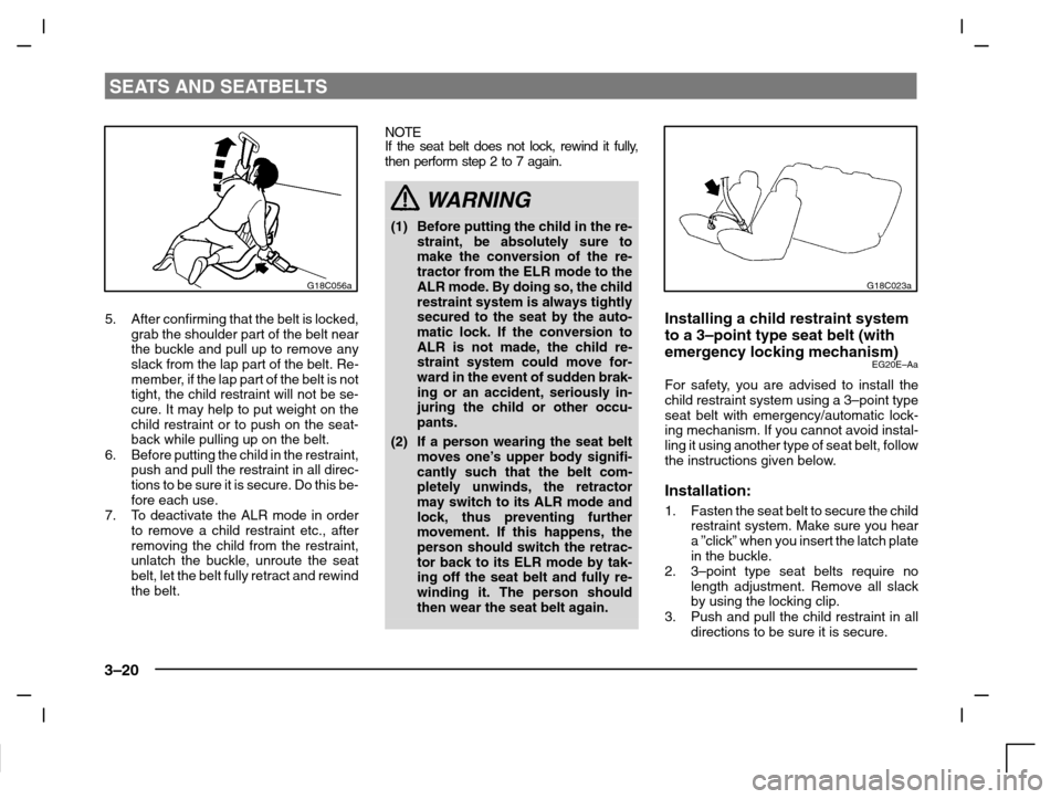
G18C056a
5. After confirming that the belt is locked,
grab the shoulder part of the belt near
the buckle and pull up to remove any
slack from the lap part of the belt. Re-
member, if the lap part of the belt is not
tight, the child restraint will not be se-
cure. It may help to put weight on the
child restraint or to push on the seat-
back while pulling up on the belt.
6. Before putting the child in the restraint,
push and pull the restraint in all direc-
tions to be sure it is secure. Do this be-
fore each use.
7. To deactivate the ALR mode in order
to remove a child restraint etc., after
removing the child from the restraint,
unlatch the buckle, unroute the seat
belt, let the belt fully retract and rewind
the belt.NOTE
If the seat belt does not lock, rewind it fully,
then perform step 2 to 7 again.
WARNING
(1) Before putting the child in the re-
straint, be absolutely sure to
make the conversion of the re-
tractor from the ELR mode to the
ALR mode. By doing so, the child
restraint system is always tightly
secured to the seat by the auto-
matic lock. If the conversion to
ALR is not made, the child re-
straint system could move for-
ward in the event of sudden brak-
ing or an accident, seriously in-
juring the child or other occu-
pants.
(2) If a person wearing the seat belt
moves one’s upper body signifi-
cantly such that the belt com-
pletely unwinds, the retractor
may switch to its ALR mode and
lock, thus preventing further
movement. If this happens, the
person should switch the retrac-
tor back to its ELR mode by tak-
ing off the seat belt and fully re-
winding it. The person should
then wear the seat belt again.
G18C023a
Installing a child restraint system
to a 3–point type seat belt (with
emergency locking mechanism)
EG20E–Aa
For safety, you are advised to install the
child restraint system using a 3–point type
seat belt with emergency/automatic lock-
ing mechanism. If you cannot avoid instal-
ling it using another type of seat belt, follow
the instructions given below.
Installation:
1. Fasten the seat belt to secure the child
restraint system. Make sure you hear
a ”click” when you insert the latch plate
in the buckle.
2. 3–point type seat belts require no
length adjustment. Remove all slack
by using the locking clip.
3. Push and pull the child restraint in all
directions to be sure it is secure.
Page 107 of 280

STARTING AND DRIVING
5–7
(3)City traffic
Frequent starting and stopping in-
creases the average fuel consumption.
Use roads with smooth traffic flow
whenever possible. When driving on
congested roads, avoid use of a low
gear at high engine speeds.
(4) Idling
The vehicle consumes fuel even during
idling. Avoid extended idling whenever
possible.
(5)Speed
The higher the vehicle speed, the more
fuel consumed. Avoid driving at full
speed. Even a slight release of the ac-
celerator pedal will save a significant
amount of fuel.
(6)Tyre inflation pressure
Check the tyre inflation pressures at
regular intervals. Low tyre inflation pres-
sure increases road resistance and fuel
consumption. In addition, low tyre pres-
sures adversely affect tyre wear and
driving stability.(7)Load
Do not drive with unnecessary articles in
the luggage compartment. Especially
during city driving where frequent start-
ing and stopping is necessary, the in-
creased weight of the vehicle will greatly
affect fuel consumption. Also avoid driv-
ing with unnecessary luggage, etc., on
the roof; the increased air resistance will
increase fuel consumption.
(8)Cold engine starting
Starting of a cold engine consumes
more fuel.
Unnecessary fuel consumption is also
caused by keeping a hot engine run-
ning. After the engine is started, com-
mence driving as soon as possible.
(9)Air conditioning*
The use of the air conditioning will in-
crease the fuel consumption.Trailer towingEC21AMFg
In order to tow a trailer with your vehicle, a
trailer towing device that meets all relevant
regulations in your area has to be mounted.
The regulations concerning the towing of a
trailer may differ from country to country. You
are advised to obey the regulations in each
area.
CAUTION
Danger of accident!
A towing bar should be fitted by an
authorized MITSUBISHI dealer.
Page 108 of 280

STARTING AND DRIVING
5–8
NOTE
Fitting of a towing bar requires specialized
skills and equipment. Contact an authorized
MITSUBISHI dealer for details.
If you are going to tow a trailer, pay careful
attention to the following points.
Maximum towable weight with brake
and maximum trailer-nose weight
Never exceed the maximum towable weight
with brake and the maximum trailer-nose
weight as listed in the specifications. (Refer
to pages from 10–6 to 10–9)
If you tow a trailer at an altitude of more than
1000m above sea-level, reduce your weight
by 10% of the gross combination weight for
every increase of 1000m above sea-level,
as the engine output is lowered owing to de-
crease in atmospheric pressure.C21A015a
Towing bar mounting
specifications
See the following table for fixing points (A) for
the towing bar.
mm
12345
1,0908051908580
678910
30518515535
1112131415
288187.5439501940
161718
4709401,002
C21A014a
Operating hints
(1) Do not let the clutch slip (vehicles with a
manual transmission only) and do not
increase the engine speed more than
necessary when starting.
(2)Be sure that the driving speed does not
exceed the 100 km/h for trailer oper-
ation.
It is also recommended that you obey
the local regulations in case driving
speed with a trailer is limited to less than
100 km/h.
(3)To prevent shocks from the overrun
brake, depress the brake pedal lightly at
first and then more strongly.
(4) To make full use of engine braking,
change to a lower gear before descend-
ing a slope.
(5) The body, brakes, clutch, and chassis
will be under additional strain when tow-
ing a trailer.
Page 109 of 280

STARTING AND DRIVING
5–9
(6) The heavier weight and higher rolling
and air resistance will increase fuel con-
sumption.
Additional precautions for vehicles
equipped with an automatic
transmission
The “2” position (INVECS–II 4A/T) or 2nd
gear (INVECS–II Sport Mode 4A/T) is re-
commended on slopes or at low speed. Use
the “L” position (INVECS–II 4A/T) or 1st gear
(INVECS–II Sport Mode 4A/T) in mountain-
ous areas in order to make better use of en-
gine braking and to assist the brake system.
However, be sure that the speed does not
exceed the maximum speed limit for the se-
lected gear.
For maximum speed of the vehicles
equipped with INVECS–II 4A/T, refer to the
description of the “Possible driving speed”
on page 5–24.Vehicles with automatic transmission
I21A070a
Ignition switchEI21AAGe
1-The engine is stopped, and the steer-
ing wheel is locked. The key can only
be inserted and removed only when
the switch is in this position.
2-The engine is stopped, but the radio,
cigarette lighter and other electrical
devices can be operated.
3-The engine is running and all the ve-
hicle’s electrical devices can be oper-
ated.
4-The starter motor operates. After the
engine has started, release the key
and it will automatically return to the
“ON” position.
Vehicles with manual transmission
I21A031a
Page 206 of 280

FOR EMERGENCIES
8–6
N22A086a
7. Insert the bar (E) into the wheel nut
wrench (F). Then set the end of the bar
to the shaft’s jack end, as shown in the
illustration.
Slowly rotate the wheel nut wrench
until the tyre is slightly off the ground.
WARNING
(1) Raise the vehicle so the tyre just
clears the ground. It is dangerous
to raise the vehicle any higher.
(2) Never get under the vehicle while
using the jack. Avoid jarring the
raised vehicle or leaving it sup-
ported on the jack for any long
time. Both are very dangerous.
(3) Do not start or run the engine
while the vehicle is on the jack.
The vehicle might start moving
and the jack might get out of the
body.
(4) Do not turn the jacked up wheels.
The tyres remaining on the
ground may turn, causing the ve-
hicle body to fall down from the
jack.
(5) No one should stay in the vehicle
while the jack is used.
CAUTION
Use only the jack included with the
vehicle, and use it only for changing
wheels.
N03A064a
Spare wheelEN03ABBaCheck the air pressure in the spare tyre
weekly, making sure it is ready for emerg-
ency use. Maintaining the spare wheel at the
highest specified air pressure will ensure that
it can always be used under any conditions
(city/high–speed driving, varying load
weight, etc.).
WARNING
When used, set to the correct tyre
pressure.