2000 DODGE NEON ESP
[x] Cancel search: ESPPage 91 of 1285
If the vacuum supply is 12 inches Hg (40.5 kPa) or
more, the power brake booster is defective and must
be replaced. If the vacuum supply is below 12 inches,
continue on with this BASIC TEST.
(6) Shut off the engine.
(7) Connect the vacuum gauge to the vacuum ref-
erence port on the engine intake manifold.
(8)
Start the engine and observe the vacuum gauge.
If the vacuum is still low, check the engine tune
and repair as necessary. If the vacuum is above 12
inches, the hose or check to the booster has a restric-
tion or leak.
Once an adequate vacuum supply is obtained,
repeat the BASIC TEST.
VACUUM LEAK TEST
(1) Disconnect the vacuum hose on the side of the
power brake booster vacuum check valve that leads
to the speed control, then connect a vacuum gauge to
the open vacuum port on the valve.
(2) Remove the remaining hose on the vacuum
check valve that is not the vacuum supply hose com-
ing from the intake manifold. Cap off the open port
on the check valve.
(3) Start the engine.
(4) Allow the engine to warm up to normal operat-
ing temperature and engine idle.
(5) Using vacuum line pliers, close off the vacuum
supply hose near the booster and observe the vacuum
gauge.
If the vacuum drop exceeds 1.0 inch Hg (3.3 kPa)
in one minute, repeat the above steps to confirm the
reading. The vacuum loss should be less than 1.0
inch Hg in one minute time span. If the loss is more
than 1.0 inch Hg, replace the power brake booster. If
it is not, continue on with this test.
(6) Remove the pliers from the hose temporarily.
(7) Apply light effort (approximately 15 lbs. of
force) to the brake pedal and hold the pedal steady.
Do not move the pedal once the pressure is applied
or the test results may vary.
(8) Have an assistant reattach the pliers to the
vacuum supply hose.
(9) Allow 5 seconds for stabilization, then observe
the vacuum gauge.
If the vacuum drop exceeds 3.0 inches Hg (10 kPa)
in 15 seconds, repeat the above steps to confirm the
reading. The vacuum loss should be less than 3.0
inches Hg in 15 seconds time span. If the loss is
more than 3.0 inches Hg, replace the power brake
booster. If it is not, the booster is not defective.
DRUM BRAKE AUTOMATIC ADJUSTER
To properly test the drum brake automatic
adjuster, the aide of a helper inside the vehicle to
apply the brakes will be necessary.(1) Raise the vehicle. Refer to HOISTING in the
LUBRICATION AND MAINTENANCE group for the
proper lifting procedure.
(2) Remove the access plug from the rear adjust-
ment slot in each brake support plate.
(3) Insert a thin screwdriver in the adjustment
slot and push back the adjustment lever. With the
lever in this position, back the star wheel adjustment
off approximately 10 notches. This will eliminate the
possibility that the brake is at full adjustment, and
can be adjusted no further.
(4)
Remove the screwdriver from the adjustment slot.
(5) Watch the star wheel through the adjustment
slot, while a helper applies the brake pedal. As the
brake shoes apply, the adjustment lever should move
downward, turning the star wheel. A definite rotation
of the adjuster star wheel can be observed if the
automatic adjuster is working properly.
If the star wheel does not move as indicated, the
brake drum needs to be removed and further inspec-
tion of the rear brakes is necessary.
(6) If the star wheel is operating properly, readjust
the brakes. Refer to ADJUSTMENTS in this section
of this service manual group.
(7) Reinstall the adjustment slot access plug.
(8) Lower the vehicle.
BRAKE ROTOR
Any servicing of the rotor requires extreme care to
maintain the rotor within service tolerances to
ensure proper brake action.
Excessive runout or wobble in a rotor can increase
pedal travel due to piston knock-back. This increases
guide pin sleeve wear due to the tendency of the cal-
iper to follow the rotor wobble.
When diagnosing a brake noise or pulsation, the
machined disc braking surface should be checked and
inspected.
BRAKING SURFACE INSPECTION
Light braking surface scoring and wear is accept-
able. If heavy scoring or warping is evident, the rotor
must be refaced or replaced. Refer to SERVICE PRO-
CEDURES in this section of this group for informa-
tion on brake rotor machining.
Excessive wear and scoring of the rotor can cause
improper lining contact on the rotor's braking sur-
face. If the ridges on the rotor are not removed before
new brake shoes are installed, improper wear of the
shoes will result.
If a vehicle has not been driven for a period of
time, the rotor's braking surface will rust in the
areas not covered by the brake shoes at that time.
Once the vehicle is driven, noise and chatter from
the disc brakes can result when the brakes are
applied.
5 - 12 BRAKESPL
DIAGNOSIS AND TESTING (Continued)
Page 93 of 1285
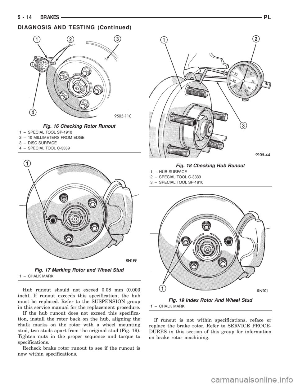
Hub runout should not exceed 0.08 mm (0.003
inch). If runout exceeds this specification, the hub
must be replaced. Refer to the SUSPENSION group
in this service manual for the replacement procedure.
If the hub runout does not exceed this specifica-
tion, install the rotor back on the hub, aligning the
chalk marks on the rotor with a wheel mounting
stud, two studs apart from the original stud (Fig. 19).
Tighten nuts in the proper sequence and torque to
specifications.
Recheck brake rotor runout to see if the runout is
now within specifications.If runout is not within specifications, reface or
replace the brake rotor. Refer to SERVICE PROCE-
DURES in this section of this group for information
on brake rotor machining.
Fig. 16 Checking Rotor Runout
1 ± SPECIAL TOOL SP-1910
2 ± 10 MILLIMETERS FROM EDGE
3 ± DISC SURFACE
4 ± SPECIAL TOOL C-3339
Fig. 17 Marking Rotor and Wheel Stud
1 ± CHALK MARK
Fig. 18 Checking Hub Runout
1 ± HUB SURFACE
2 ± SPECIAL TOOL C-3339
3 ± SPECIAL TOOL SP-1910
Fig. 19 Index Rotor And Wheel Stud
1 ± CHALK MARK
5 - 14 BRAKESPL
DIAGNOSIS AND TESTING (Continued)
Page 95 of 1285
The in-line proportioning valves used on this vehi-
cle require special pressure fittings to test the pro-
portioning valves for proper proportioning valve
function. The pressure fittings are installed before
and after the proportioning valve being tested to ver-
ify proportioning valve is maintaining the required
hydraulic pressure to the rear wheel brake which it
controls.
The testing of proportioning valves for this vehicle,
if equipped with ABS, can be found in the
ANTILOCK BRAKE SYSTEM section.
PROPORTIONING VALVE TEST
The test procedure is the same for either rear pro-
portioning valve. After road testing the vehicle to
determine which wheel skids first, follow the proce-
dure below for testing the suspect proportioning
valve.
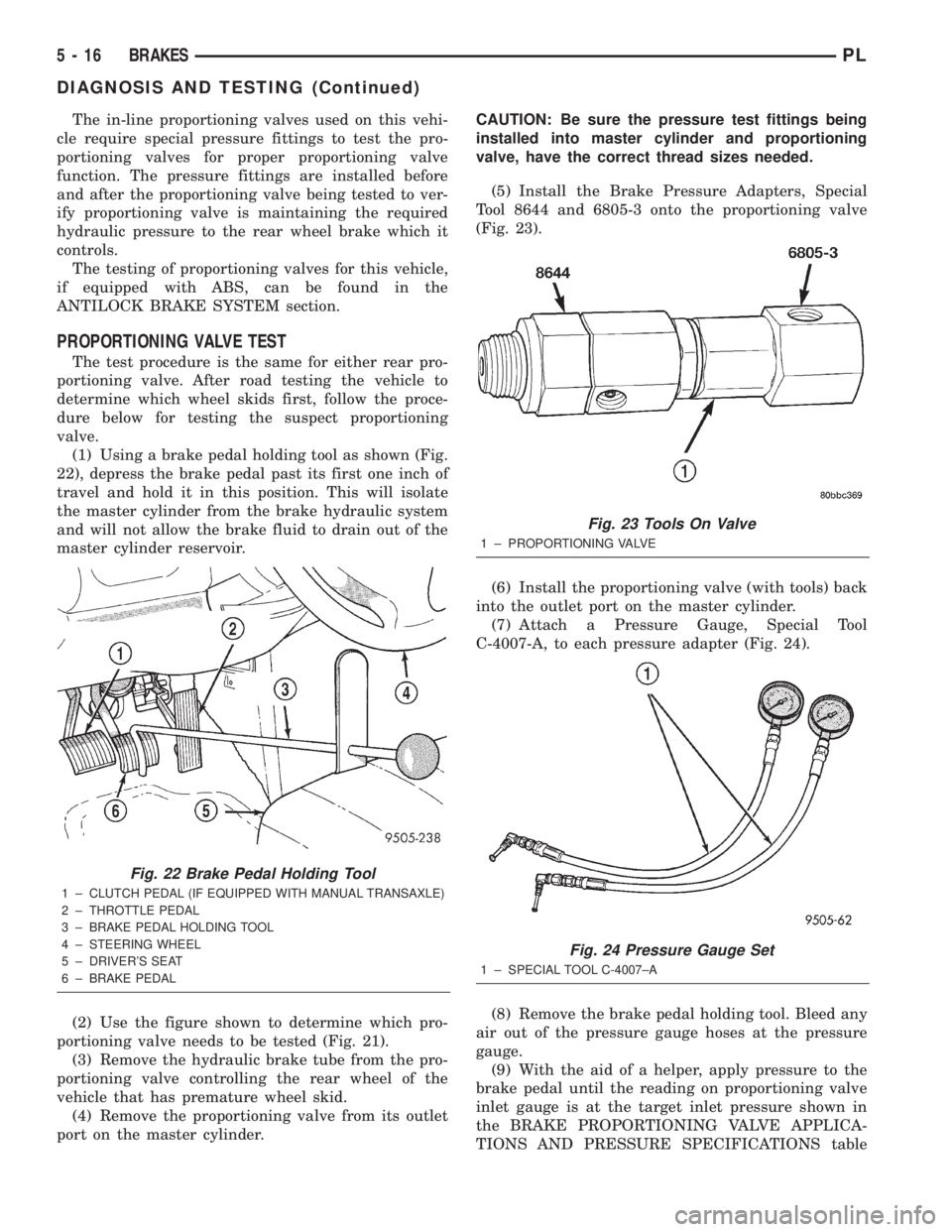
(1) Using a brake pedal holding tool as shown (Fig.
22), depress the brake pedal past its first one inch of
travel and hold it in this position. This will isolate
the master cylinder from the brake hydraulic system
and will not allow the brake fluid to drain out of the
master cylinder reservoir.
(2) Use the figure shown to determine which pro-
portioning valve needs to be tested (Fig. 21).
(3) Remove the hydraulic brake tube from the pro-
portioning valve controlling the rear wheel of the
vehicle that has premature wheel skid.
(4) Remove the proportioning valve from its outlet
port on the master cylinder.CAUTION: Be sure the pressure test fittings being
installed into master cylinder and proportioning
valve, have the correct thread sizes needed.
(5) Install the Brake Pressure Adapters, Special
Tool 8644 and 6805-3 onto the proportioning valve
(Fig. 23).
(6) Install the proportioning valve (with tools) back
into the outlet port on the master cylinder.
(7) Attach a Pressure Gauge, Special Tool
C-4007-A, to each pressure adapter (Fig. 24).
(8) Remove the brake pedal holding tool. Bleed any
air out of the pressure gauge hoses at the pressure
gauge.
(9) With the aid of a helper, apply pressure to the
brake pedal until the reading on proportioning valve
inlet gauge is at the target inlet pressure shown in
the BRAKE PROPORTIONING VALVE APPLICA-
TIONS AND PRESSURE SPECIFICATIONS table
Fig. 22 Brake Pedal Holding Tool
1 ± CLUTCH PEDAL (IF EQUIPPED WITH MANUAL TRANSAXLE)
2 ± THROTTLE PEDAL
3 ± BRAKE PEDAL HOLDING TOOL
4 ± STEERING WHEEL
5 ± DRIVER'S SEAT
6 ± BRAKE PEDAL
Fig. 23 Tools On Valve
1 ± PROPORTIONING VALVE
Fig. 24 Pressure Gauge Set
1 ± SPECIAL TOOL C-4007±A
5 - 16 BRAKESPL
DIAGNOSIS AND TESTING (Continued)
Page 97 of 1285
CAUTION: Before removing the master cylinder
cap, wipe it clean to prevent dirt and other foreign
matter from dropping into the master cylinder res-
ervoir.
CAUTION: Use only MoparTbrake fluid or an equiv-
alent from a fresh, tightly sealed container. Brake
fluid must conform to DOT 3 specifications.
Do not pump the brake pedal at any time while
having a bleeder screw open during the bleeding pro-
cess. This will only increase the amount of air in the
system and make additional bleeding necessary.
Do not allow the master cylinder reservoir to run
out of brake fluid while bleeding the system. An
empty reservoir will allow additional air into the
brake system. Check the fluid level frequently and
add fluid as needed.
The following wheel circuit sequence for bleeding
the brake hydraulic system should be used to ensure
adequate removal of all trapped air from the hydrau-
lic system.
²Left rear wheel
²Right front wheel
²Right rear wheel
²Left front wheel
MANUAL BLEEDING
NOTE: To bleed the brakes manually, the aid of a
helper will be required.
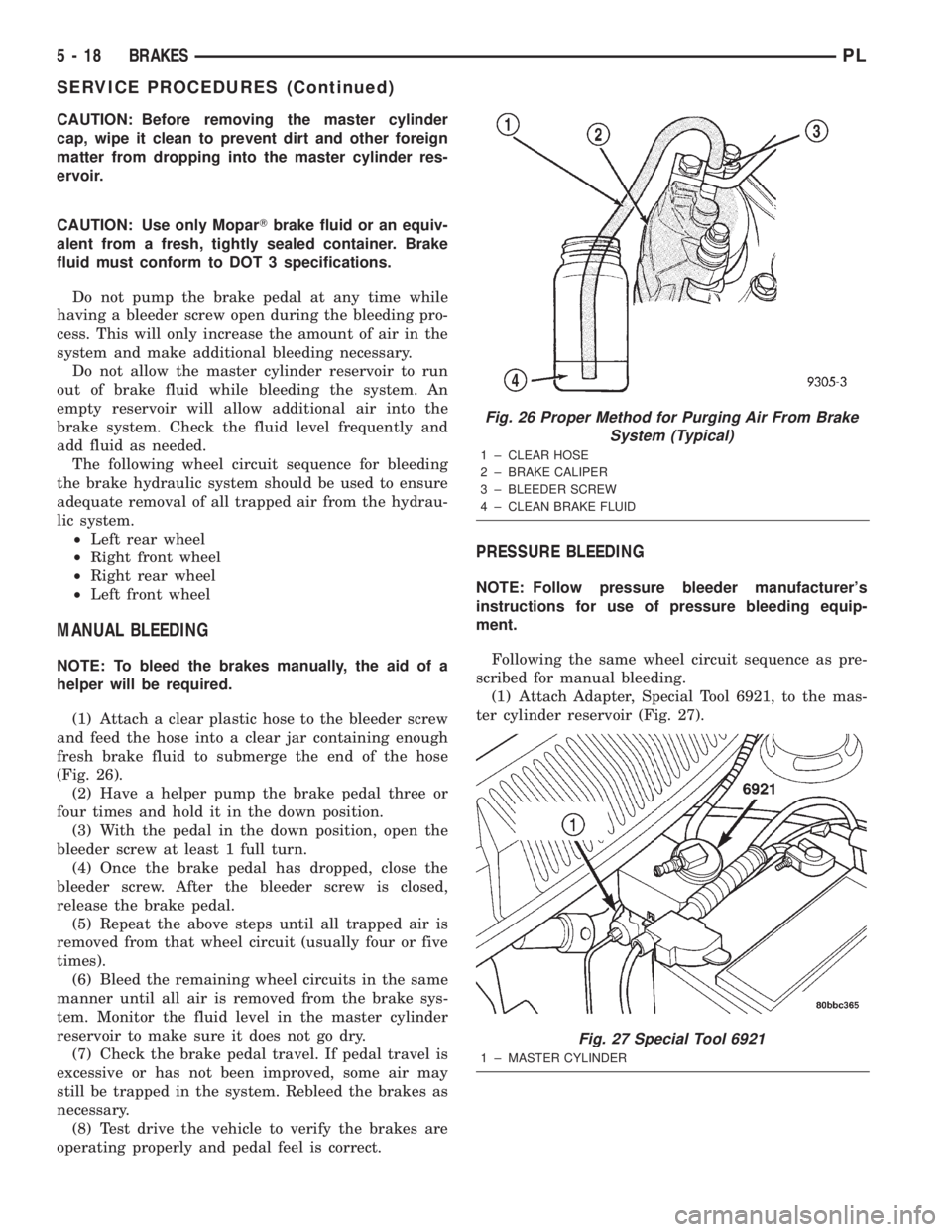
(1) Attach a clear plastic hose to the bleeder screw
and feed the hose into a clear jar containing enough
fresh brake fluid to submerge the end of the hose
(Fig. 26).
(2) Have a helper pump the brake pedal three or
four times and hold it in the down position.
(3) With the pedal in the down position, open the
bleeder screw at least 1 full turn.
(4) Once the brake pedal has dropped, close the
bleeder screw. After the bleeder screw is closed,
release the brake pedal.
(5) Repeat the above steps until all trapped air is
removed from that wheel circuit (usually four or five
times).
(6) Bleed the remaining wheel circuits in the same
manner until all air is removed from the brake sys-
tem. Monitor the fluid level in the master cylinder
reservoir to make sure it does not go dry.
(7) Check the brake pedal travel. If pedal travel is
excessive or has not been improved, some air may
still be trapped in the system. Rebleed the brakes as
necessary.
(8) Test drive the vehicle to verify the brakes are
operating properly and pedal feel is correct.
PRESSURE BLEEDING
NOTE: Follow pressure bleeder manufacturer's
instructions for use of pressure bleeding equip-
ment.
Following the same wheel circuit sequence as pre-
scribed for manual bleeding.
(1) Attach Adapter, Special Tool 6921, to the mas-
ter cylinder reservoir (Fig. 27).
Fig. 26 Proper Method for Purging Air From Brake
System (Typical)
1 ± CLEAR HOSE
2 ± BRAKE CALIPER
3 ± BLEEDER SCREW
4 ± CLEAN BRAKE FLUID
Fig. 27 Special Tool 6921
1 ± MASTER CYLINDER
5 - 18 BRAKESPL
SERVICE PROCEDURES (Continued)
Page 99 of 1285
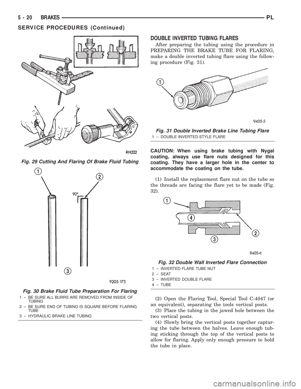
DOUBLE INVERTED TUBING FLARES
After preparing the tubing using the procedure in
PREPARING THE BRAKE TUBE FOR FLARING,
make a double inverted tubing flare using the follow-
ing procedure (Fig. 31).
CAUTION: When using brake tubing with Nygal
coating, always use flare nuts designed for this
coating. They have a larger hole in the center to
accommodate the coating on the tube.
(1) Install the replacement flare nut on the tube so
the threads are facing the flare yet to be made (Fig.
32).
(2) Open the Flaring Tool, Special Tool C-4047 (or
an equivalent), separating the tools vertical posts.
(3) Place the tubing in the jawed hole between the
two vertical posts.
(4) Slowly bring the vertical posts together captur-
ing the tube between the halves. Leave enough tub-
ing sticking through the top of the vertical posts to
allow for flaring. Apply only enough pressure to hold
the tube in place.
Fig. 29 Cutting And Flaring Of Brake Fluid Tubing
Fig. 30 Brake Fluid Tube Preparation For Flaring
1 ± BE SURE ALL BURRS ARE REMOVED FROM INSIDE OF
TUBING
2 ± BE SURE END OF TUBING IS SQUARE BEFORE FLARING
TUBE
3 ± HYDRAULIC BRAKE LINE TUBING
Fig. 31 Double Inverted Brake Line Tubing Flare
1 ± DOUBLE INVERTED-STYLE FLARE
Fig. 32 Double Wall Inverted Flare Connection
1 ± INVERTED FLARE TUBE NUT
2 ± SEAT
3 ± INVERTED DOUBLE FLARE
4 ± TUBE
5 - 20 BRAKESPL
SERVICE PROCEDURES (Continued)
Page 101 of 1285
BRAKE ROTOR LIMITS
Braking Rotor Rotor ThicknessMinimum
Rotor
ThicknessRotor
Thickness
VariationRotor Run
Out*Rotor Micro
Finish
Front Rotor21.87±22.13 mm
0.861-0.871 in.20.4 mm
0.803 in.0.013 mm
0.0005 in.0.08 mm
0.003 in.15-80 RMS
Rear Rotor8.75±9.25 mm
0.344 -0.364 in.7.25 mm
0.285 in.0.013 mm
0.0005 in.0.08 mm
0.003 in.15-80 RMS
* TIR Total Indicator Reading (Measured On Vehicle)
BRAKE DRUM MACHINING
If a brake drum is deeply scored or warped, it can
be machined on a brake lathe equipped to machine
brake drums. Follow the manufacturers instructions
on the machining procedure.
Measure the brake drum diameter before machin-
ing. If machining the drum will cause the drum to
exceed maximum allowable diameter, do not machine
the brake drum. It needs to be replaced.
CAUTION: Do not machine the brake drum if it will
cause the drum to exceed maximum allowable
diameter.
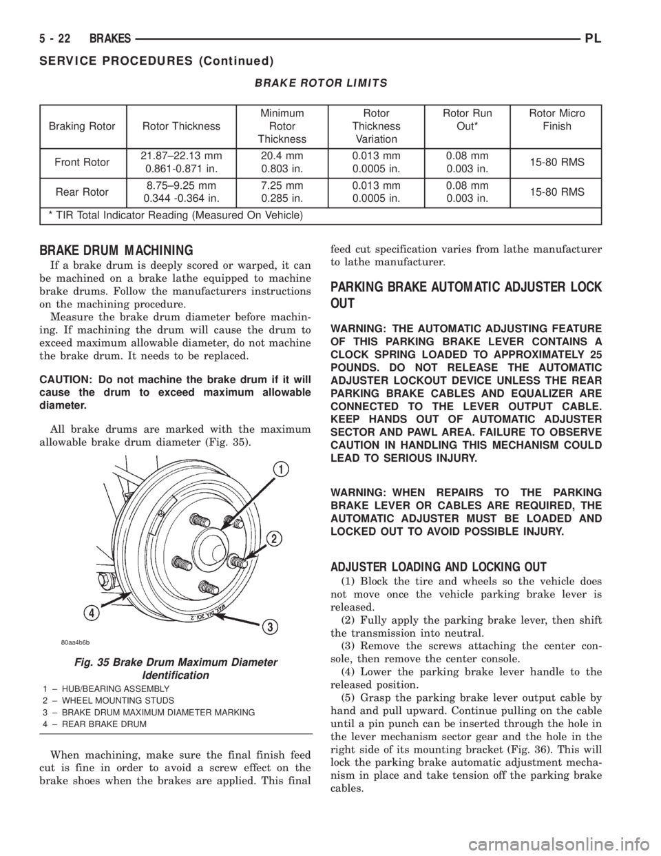
All brake drums are marked with the maximum
allowable brake drum diameter (Fig. 35).
When machining, make sure the final finish feed
cut is fine in order to avoid a screw effect on the
brake shoes when the brakes are applied. This finalfeed cut specification varies from lathe manufacturer
to lathe manufacturer.
PARKING BRAKE AUTOMATIC ADJUSTER LOCK
OUT
WARNING: THE AUTOMATIC ADJUSTING FEATURE
OF THIS PARKING BRAKE LEVER CONTAINS A
CLOCK SPRING LOADED TO APPROXIMATELY 25
POUNDS. DO NOT RELEASE THE AUTOMATIC
ADJUSTER LOCKOUT DEVICE UNLESS THE REAR
PARKING BRAKE CABLES AND EQUALIZER ARE
CONNECTED TO THE LEVER OUTPUT CABLE.
KEEP HANDS OUT OF AUTOMATIC ADJUSTER
SECTOR AND PAWL AREA. FAILURE TO OBSERVE
CAUTION IN HANDLING THIS MECHANISM COULD
LEAD TO SERIOUS INJURY.
WARNING: WHEN REPAIRS TO THE PARKING
BRAKE LEVER OR CABLES ARE REQUIRED, THE
AUTOMATIC ADJUSTER MUST BE LOADED AND
LOCKED OUT TO AVOID POSSIBLE INJURY.
ADJUSTER LOADING AND LOCKING OUT
(1) Block the tire and wheels so the vehicle does
not move once the vehicle parking brake lever is
released.
(2) Fully apply the parking brake lever, then shift
the transmission into neutral.
(3) Remove the screws attaching the center con-
sole, then remove the center console.
(4) Lower the parking brake lever handle to the
released position.
(5) Grasp the parking brake lever output cable by
hand and pull upward. Continue pulling on the cable
until a pin punch can be inserted through the hole in
the lever mechanism sector gear and the hole in the
right side of its mounting bracket (Fig. 36). This will
lock the parking brake automatic adjustment mecha-
nism in place and take tension off the parking brake
cables.
Fig. 35 Brake Drum Maximum Diameter
Identification
1 ± HUB/BEARING ASSEMBLY
2 ± WHEEL MOUNTING STUDS
3 ± BRAKE DRUM MAXIMUM DIAMETER MARKING
4 ± REAR BRAKE DRUM
5 - 22 BRAKESPL
SERVICE PROCEDURES (Continued)
Page 102 of 1285
ADJUSTER UNLOADING (UNLOCKING)
NOTE: The parking brake lever can only be in the
released position when releasing the automatic
adjuster locking pin or pin punch.
(1) Be sure the rear parking brake cables are both
properly installed in the equalizer.
(2) Keeping your hands clear of the automatic
adjuster sector and pawl area, firmly grasp the park-
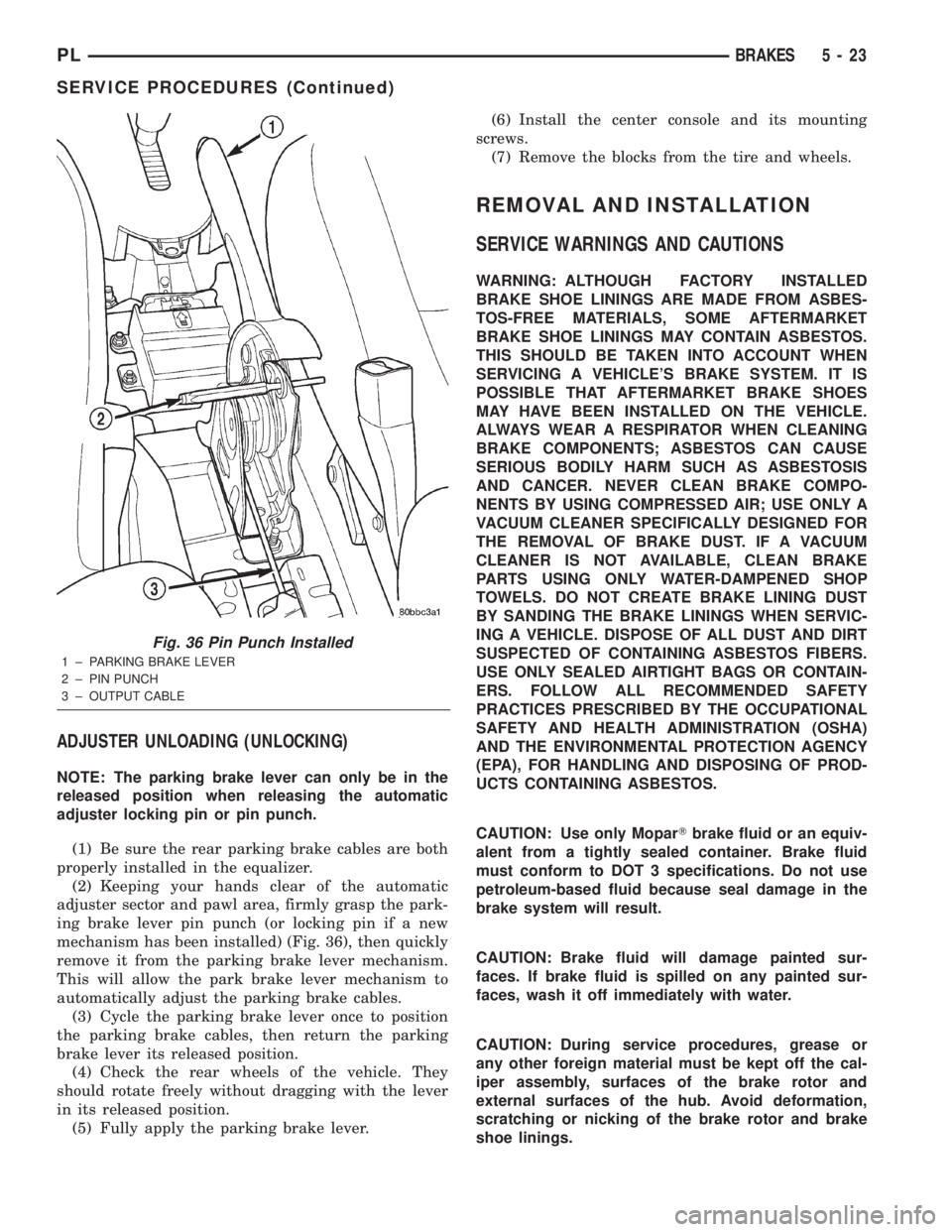
ing brake lever pin punch (or locking pin if a new
mechanism has been installed) (Fig. 36), then quickly
remove it from the parking brake lever mechanism.
This will allow the park brake lever mechanism to
automatically adjust the parking brake cables.
(3) Cycle the parking brake lever once to position
the parking brake cables, then return the parking
brake lever its released position.
(4) Check the rear wheels of the vehicle. They
should rotate freely without dragging with the lever
in its released position.
(5) Fully apply the parking brake lever.(6) Install the center console and its mounting
screws.
(7) Remove the blocks from the tire and wheels.
REMOVAL AND INSTALLATION
SERVICE WARNINGS AND CAUTIONS
WARNING: ALTHOUGH FACTORY INSTALLED
BRAKE SHOE LININGS ARE MADE FROM ASBES-
TOS-FREE MATERIALS, SOME AFTERMARKET
BRAKE SHOE LININGS MAY CONTAIN ASBESTOS.
THIS SHOULD BE TAKEN INTO ACCOUNT WHEN
SERVICING A VEHICLE'S BRAKE SYSTEM. IT IS
POSSIBLE THAT AFTERMARKET BRAKE SHOES
MAY HAVE BEEN INSTALLED ON THE VEHICLE.
ALWAYS WEAR A RESPIRATOR WHEN CLEANING
BRAKE COMPONENTS; ASBESTOS CAN CAUSE
SERIOUS BODILY HARM SUCH AS ASBESTOSIS
AND CANCER. NEVER CLEAN BRAKE COMPO-
NENTS BY USING COMPRESSED AIR; USE ONLY A
VACUUM CLEANER SPECIFICALLY DESIGNED FOR
THE REMOVAL OF BRAKE DUST. IF A VACUUM
CLEANER IS NOT AVAILABLE, CLEAN BRAKE
PARTS USING ONLY WATER-DAMPENED SHOP
TOWELS. DO NOT CREATE BRAKE LINING DUST
BY SANDING THE BRAKE LININGS WHEN SERVIC-
ING A VEHICLE. DISPOSE OF ALL DUST AND DIRT
SUSPECTED OF CONTAINING ASBESTOS FIBERS.
USE ONLY SEALED AIRTIGHT BAGS OR CONTAIN-
ERS. FOLLOW ALL RECOMMENDED SAFETY
PRACTICES PRESCRIBED BY THE OCCUPATIONAL
SAFETY AND HEALTH ADMINISTRATION (OSHA)
AND THE ENVIRONMENTAL PROTECTION AGENCY
(EPA), FOR HANDLING AND DISPOSING OF PROD-
UCTS CONTAINING ASBESTOS.
CAUTION: Use only MoparTbrake fluid or an equiv-
alent from a tightly sealed container. Brake fluid
must conform to DOT 3 specifications. Do not use
petroleum-based fluid because seal damage in the
brake system will result.
CAUTION: Brake fluid will damage painted sur-
faces. If brake fluid is spilled on any painted sur-
faces, wash it off immediately with water.
CAUTION: During service procedures, grease or
any other foreign material must be kept off the cal-
iper assembly, surfaces of the brake rotor and
external surfaces of the hub. Avoid deformation,
scratching or nicking of the brake rotor and brake
shoe linings.
Fig. 36 Pin Punch Installed
1 ± PARKING BRAKE LEVER
2 ± PIN PUNCH
3 ± OUTPUT CABLE
PLBRAKES 5 - 23
SERVICE PROCEDURES (Continued)
Page 103 of 1285
BRAKE PEDAL
NOTE: Before proceeding with this procedure,
review SERVICE WARNINGS AND CAUTIONS at the
beginning of REMOVAL AND INSTALLATION in this
section.
WITH AUTOMATIC TRANSAXLE
REMOVAL
(1) Disconnect and isolate the battery negative
cable from its post on the battery.
(2) Place the steering wheel and tires in the
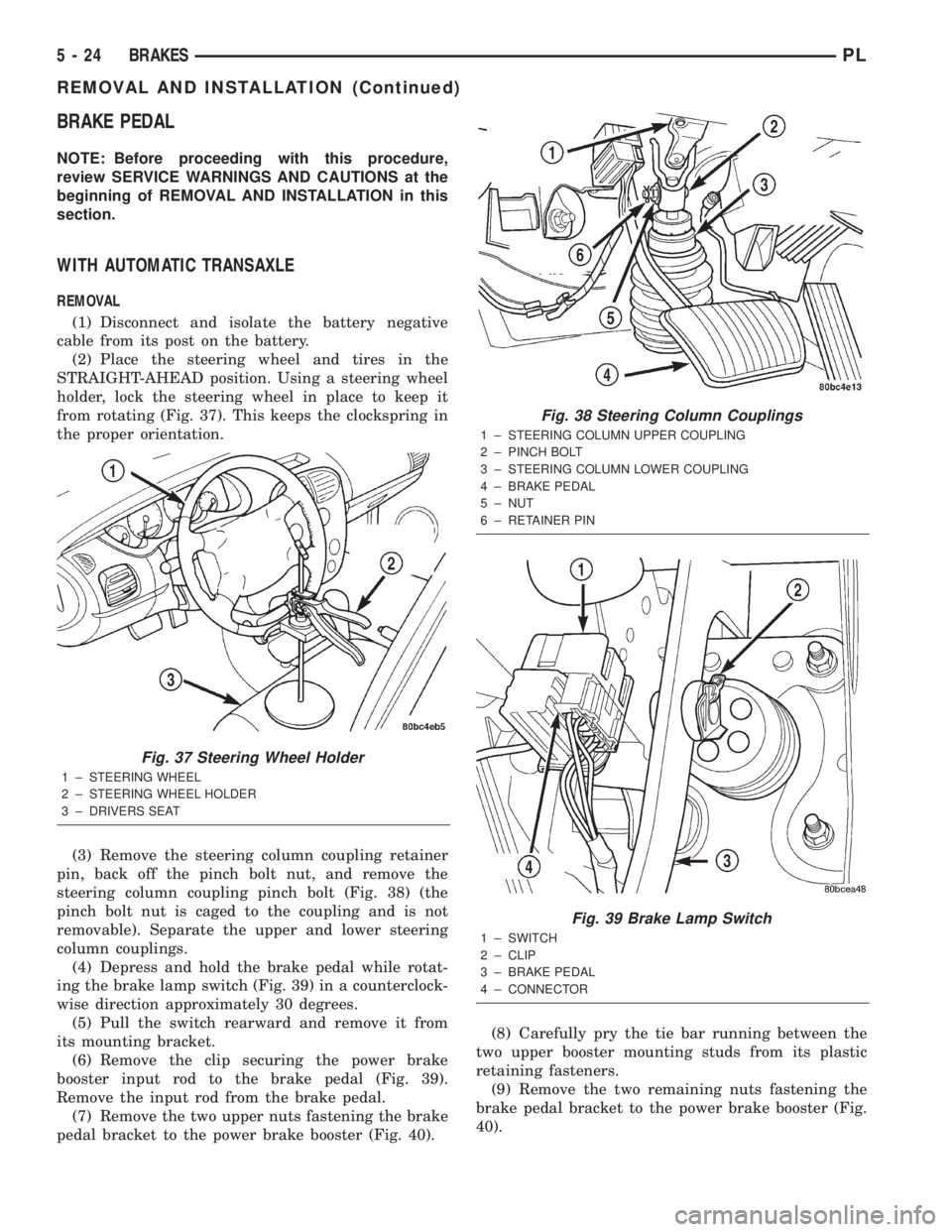
STRAIGHT-AHEAD position. Using a steering wheel
holder, lock the steering wheel in place to keep it
from rotating (Fig. 37). This keeps the clockspring in
the proper orientation.
(3) Remove the steering column coupling retainer
pin, back off the pinch bolt nut, and remove the
steering column coupling pinch bolt (Fig. 38) (the
pinch bolt nut is caged to the coupling and is not
removable). Separate the upper and lower steering
column couplings.
(4) Depress and hold the brake pedal while rotat-
ing the brake lamp switch (Fig. 39) in a counterclock-
wise direction approximately 30 degrees.
(5) Pull the switch rearward and remove it from
its mounting bracket.
(6) Remove the clip securing the power brake
booster input rod to the brake pedal (Fig. 39).
Remove the input rod from the brake pedal.
(7) Remove the two upper nuts fastening the brake
pedal bracket to the power brake booster (Fig. 40).(8) Carefully pry the tie bar running between the
two upper booster mounting studs from its plastic
retaining fasteners.
(9) Remove the two remaining nuts fastening the
brake pedal bracket to the power brake booster (Fig.
40).
Fig. 37 Steering Wheel Holder
1 ± STEERING WHEEL
2 ± STEERING WHEEL HOLDER
3 ± DRIVERS SEAT
Fig. 38 Steering Column Couplings
1 ± STEERING COLUMN UPPER COUPLING
2 ± PINCH BOLT
3 ± STEERING COLUMN LOWER COUPLING
4 ± BRAKE PEDAL
5 ± NUT
6 ± RETAINER PIN
Fig. 39 Brake Lamp Switch
1 ± SWITCH
2 ± CLIP
3 ± BRAKE PEDAL
4 ± CONNECTOR
5 - 24 BRAKESPL
REMOVAL AND INSTALLATION (Continued)