2000 DODGE NEON mounts
[x] Cancel search: mountsPage 22 of 1285
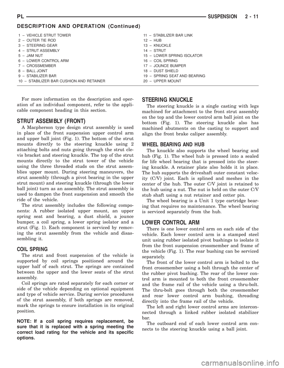
For more information on the description and oper-
ation of an individual component, refer to the appli-
cable component heading in this section.
STRUT ASSEMBLY (FRONT)
A Macpherson type design strut assembly is used
in place of the front suspension upper control arm
and upper ball joint (Fig. 1). The bottom of the strut
mounts directly to the steering knuckle using 2
attaching bolts and nuts going through the strut cle-
vis bracket and steering knuckle. The top of the strut
mounts directly to the strut tower of the vehicle
using the three threaded studs on the strut assem-
blies upper mount. During steering maneuvers, the
strut assembly (through a pivot bearing in the upper
strut mount) and steering knuckle (through the lower
ball joint) turn as an assembly. The strut assembly is
used to dampen the front suspension and smooth the
ride of the vehicle.
The strut assembly includes the following compo-
nents: A rubber isolated upper mount, an upper
spring seat and bearing, a dust shield, a jounce
bumper, a coil spring, a lower spring isolator and a
strut (Fig. 1). Each component is serviced by remov-
ing the strut assembly from the vehicle and disas-
sembling it.
COIL SPRING
The strut and front suspension of the vehicle is
supported by coil springs positioned around the
upper half of each strut. The springs are contained
between the upper and the lower seats of the strut
assembly.
Coil springs are rated separately for each corner or
side of the vehicle depending on optional equipment
and type of vehicle service. During service procedures
of the strut assembly, if both springs are removed,
mark the springs to ensure installation in its original
position.
NOTE: If a coil spring requires replacement, be
sure that it is replaced with a spring meeting the
correct load rating for the vehicle and its specific
options.
STEERING KNUCKLE
The steering knuckle is a single casting with legs
machined for attachment to the front strut assembly
on the top and the lower control arm ball joint on the
bottom (Fig. 1). The steering knuckle also has
machined abutments on the casting to support and
align the front brake caliper assembly.
WHEEL BEARING AND HUB
The knuckle also supports the wheel bearing and
hub (Fig. 1). The wheel hub is pressed into a sealed
for life wheel bearing that is pressed into the steer-
ing knuckle. A retainer plate also holds it in place.
The hub supports the driveshaft outer constant veloc-
ity (C/V) joint. Each is splined and meshes in the
center of the hub. The outer C/V joint is retained to
the hub using a nut. The nut is held on the outer C/V
stub shaft using a nut retainer and cotter pin.
The wheel bearing is a Unit 1 type cartridge bear-
ing that requires no maintenance. The wheel bearing
is serviced separately from the hub.
LOWER CONTROL ARM
There is one lower control arm on each side of the
vehicle. Each lower control arm is a stamped steel
unit using rubber isolated pivot bushings to isolate it
from the front suspension crossmember and frame of
the vehicle (Fig. 1). The rear bushing can be serviced
separately.
The front of the lower control arm is bolted to the
front crossmember using a bolt through the center of
the rubber pivot bushing. The rear of the lower con-
trol arm is mounted to both the front crossmember
and the frame rail of the vehicle using a thru-bolt.
The thru-bolt goes through both the crossmember
and rear lower control arm bushing, threading
directly into the frame rail of the vehicle.
The left and right lower control arms are intercon-
nected through a linked rubber isolated stabilizer
bar.
The outboard end of each lower control arm con-
nects to the steering knuckle using a ball joint.
1 ± VEHICLE STRUT TOWER
2 ± OUTER TIE ROD
3 ± STEERING GEAR
4 ± STRUT ASSEMBLY
5 ± JAM NUT
6 ± LOWER CONTROL ARM
7 ± CROSSMEMBER
8 ± BALL JOINT
9 ± STABILIZER BAR
10 ± STABILIZER BAR CUSHION AND RETAINER11 ± STABILIZER BAR LINK
12 ± HUB
13 ± KNUCKLE
14 ± STRUT
15 ± LOWER SPRING ISOLATOR
16 ± COIL SPRING
17 ± JOUNCE BUMPER
18 ± DUST SHIELD
19 ± SPRING SEAT AND BEARING
20 ± UPPER MOUNT
PLSUSPENSION 2 - 11
DESCRIPTION AND OPERATION (Continued)
Page 60 of 1285
²Check the upper mount for cracks and distortion
and its retaining studs for any sign of damage.
²Inspect the dust shield for rips and deteriora-
tion.
²Inspect the upper and lower spring isolators for
material deterioration and distortion.
²Inspect the coil spring for any sign of damage to
the coating.
ASSEMBLY
NOTE: If the coil spring has been removed from the
spring compressor, proceed with the next step, oth-
erwise, proceed with step 3.
(1) Place the coil spring in the compressor follow-
ing the manufacturers instructions. Before compress-
ing the spring, rotate the spring to the position
determined in the note prior to step 9 in disassembly.
(2) Slowly compress the coil spring until enough
room is available for strut assembly reassembly.
(3) Install the lower spring isolator on the lower
spring seat of the strut matching the step built intothe isolator with the step in the lower spring seat on
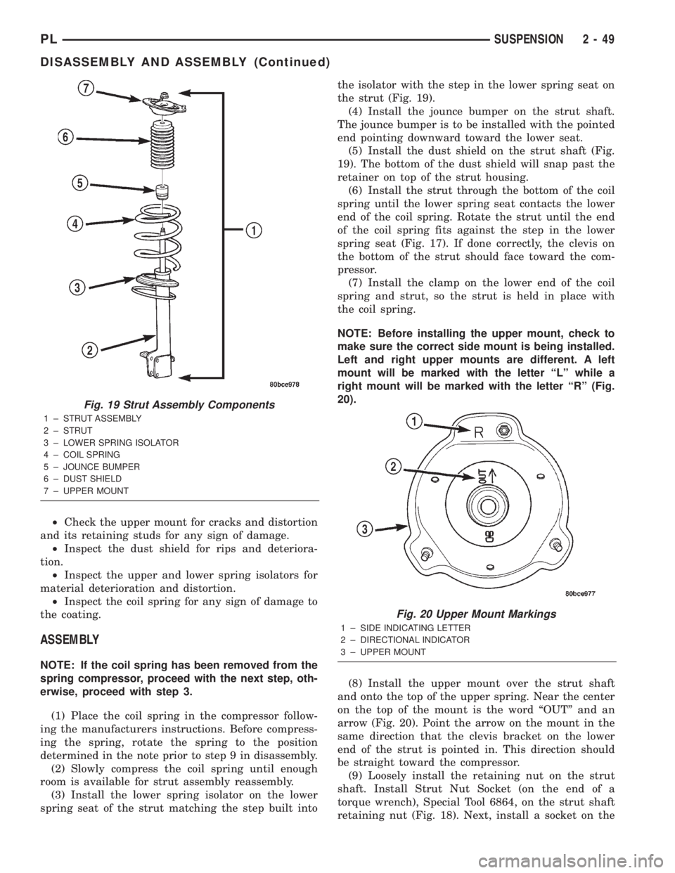
the strut (Fig. 19).
(4) Install the jounce bumper on the strut shaft.
The jounce bumper is to be installed with the pointed
end pointing downward toward the lower seat.
(5) Install the dust shield on the strut shaft (Fig.
19). The bottom of the dust shield will snap past the
retainer on top of the strut housing.
(6) Install the strut through the bottom of the coil
spring until the lower spring seat contacts the lower
end of the coil spring. Rotate the strut until the end
of the coil spring fits against the step in the lower
spring seat (Fig. 17). If done correctly, the clevis on
the bottom of the strut should face toward the com-
pressor.
(7) Install the clamp on the lower end of the coil
spring and strut, so the strut is held in place with
the coil spring.
NOTE: Before installing the upper mount, check to
make sure the correct side mount is being installed.
Left and right upper mounts are different. A left
mount will be marked with the letter ªLº while a
right mount will be marked with the letter ªRº (Fig.
20).
(8) Install the upper mount over the strut shaft
and onto the top of the upper spring. Near the center
on the top of the mount is the word ªOUTº and an
arrow (Fig. 20). Point the arrow on the mount in the
same direction that the clevis bracket on the lower
end of the strut is pointed in. This direction should
be straight toward the compressor.
(9) Loosely install the retaining nut on the strut
shaft. Install Strut Nut Socket (on the end of a
torque wrench), Special Tool 6864, on the strut shaft
retaining nut (Fig. 18). Next, install a socket on the
Fig. 19 Strut Assembly Components
1 ± STRUT ASSEMBLY
2 ± STRUT
3 ± LOWER SPRING ISOLATOR
4 ± COIL SPRING
5 ± JOUNCE BUMPER
6 ± DUST SHIELD
7 ± UPPER MOUNT
Fig. 20 Upper Mount Markings
1 ± SIDE INDICATING LETTER
2 ± DIRECTIONAL INDICATOR
3 ± UPPER MOUNT
PLSUSPENSION 2 - 49
DISASSEMBLY AND ASSEMBLY (Continued)
Page 82 of 1285
The power brake vacuum booster assembly mounts
on the engine side of the dash panel. The booster
input push rod connects to the brake pedal. A vac-
uum line connects the power booster to the intake
manifold. The master cylinder is bolted to the front
of the power brake booster.
MASTER CYLINDER
The base brakes on a vehicle not equipped with
ABS use a standard compensating port master cylin-
der, while vehicles equipped with ABS use a center
valve design master cylinder. The information pro-
vided here applies only to the non-ABS master cylin-
der. For information on the master cylinder used on
vehicles with ABS, refer to the ANTILOCK BRAKE
SYSTEM section in this service manual group.
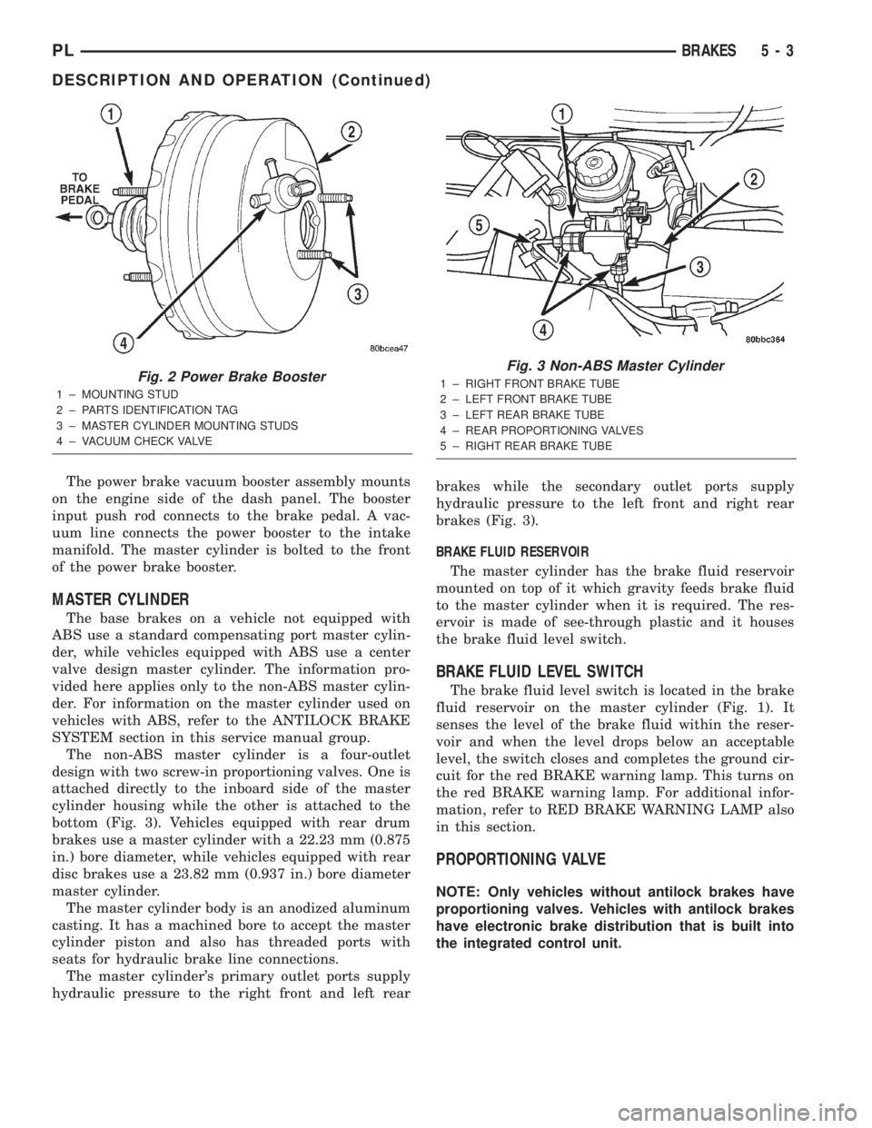
The non-ABS master cylinder is a four-outlet
design with two screw-in proportioning valves. One is
attached directly to the inboard side of the master
cylinder housing while the other is attached to the
bottom (Fig. 3). Vehicles equipped with rear drum
brakes use a master cylinder with a 22.23 mm (0.875
in.) bore diameter, while vehicles equipped with rear
disc brakes use a 23.82 mm (0.937 in.) bore diameter
master cylinder.
The master cylinder body is an anodized aluminum
casting. It has a machined bore to accept the master
cylinder piston and also has threaded ports with
seats for hydraulic brake line connections.
The master cylinder's primary outlet ports supply
hydraulic pressure to the right front and left rearbrakes while the secondary outlet ports supply
hydraulic pressure to the left front and right rear
brakes (Fig. 3).
BRAKE FLUID RESERVOIR
The master cylinder has the brake fluid reservoir
mounted on top of it which gravity feeds brake fluid
to the master cylinder when it is required. The res-
ervoir is made of see-through plastic and it houses
the brake fluid level switch.
BRAKE FLUID LEVEL SWITCH
The brake fluid level switch is located in the brake
fluid reservoir on the master cylinder (Fig. 1). It
senses the level of the brake fluid within the reser-
voir and when the level drops below an acceptable
level, the switch closes and completes the ground cir-
cuit for the red BRAKE warning lamp. This turns on
the red BRAKE warning lamp. For additional infor-
mation, refer to RED BRAKE WARNING LAMP also
in this section.
PROPORTIONING VALVE
NOTE: Only vehicles without antilock brakes have
proportioning valves. Vehicles with antilock brakes
have electronic brake distribution that is built into
the integrated control unit.
Fig. 2 Power Brake Booster
1 ± MOUNTING STUD
2 ± PARTS IDENTIFICATION TAG
3 ± MASTER CYLINDER MOUNTING STUDS
4 ± VACUUM CHECK VALVE
Fig. 3 Non-ABS Master Cylinder
1 ± RIGHT FRONT BRAKE TUBE
2 ± LEFT FRONT BRAKE TUBE
3 ± LEFT REAR BRAKE TUBE
4 ± REAR PROPORTIONING VALVES
5 ± RIGHT REAR BRAKE TUBE
PLBRAKES 5 - 3
DESCRIPTION AND OPERATION (Continued)
Page 86 of 1285
The adapter is used to mount the brake caliper to the
vehicle (Fig. 9). The adapter has two machined abut-
ments, which are used to position and align the cal-
iper and brake pads for movement inboard and
outboard. The adapter also mounts the parking brake
shoes and actuating cables to the vehicle.
PARKING BRAKES
The parking brakes (Fig. 4) consist of the following
components:
²Hand-operated park brake lever - automatic-ad-
justing
²Parking brake cables
²Actuation levers and struts
²Duo-servo parking brake assembly (rear disc
only)
PARKING BRAKE LEVER
All vehicles are equipped with a center-mounted,
hand-operated parking brake lever mounted between
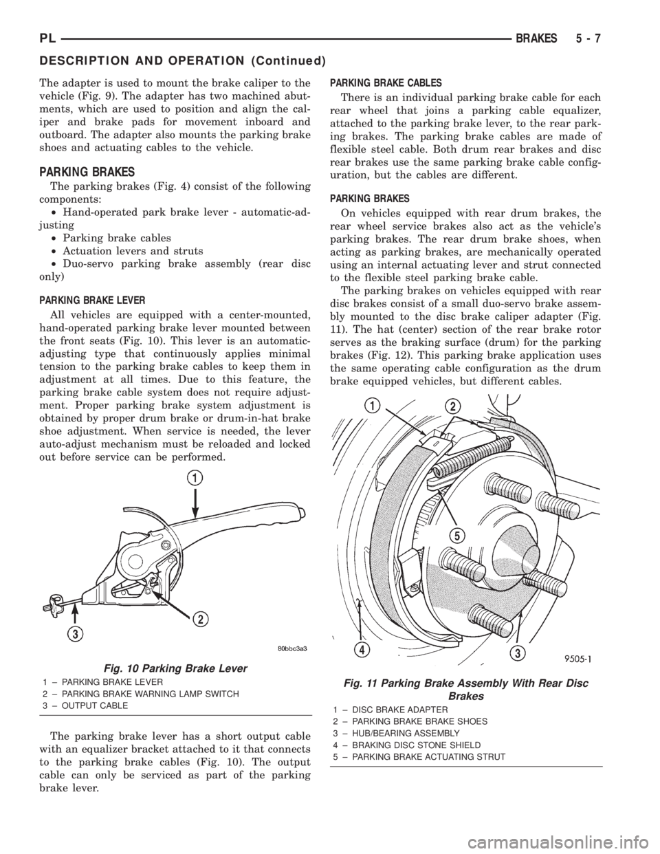
the front seats (Fig. 10). This lever is an automatic-
adjusting type that continuously applies minimal
tension to the parking brake cables to keep them in
adjustment at all times. Due to this feature, the
parking brake cable system does not require adjust-
ment. Proper parking brake system adjustment is
obtained by proper drum brake or drum-in-hat brake
shoe adjustment. When service is needed, the lever
auto-adjust mechanism must be reloaded and locked
out before service can be performed.
The parking brake lever has a short output cable
with an equalizer bracket attached to it that connects
to the parking brake cables (Fig. 10). The output
cable can only be serviced as part of the parking
brake lever.PARKING BRAKE CABLES
There is an individual parking brake cable for each
rear wheel that joins a parking cable equalizer,
attached to the parking brake lever, to the rear park-
ing brakes. The parking brake cables are made of
flexible steel cable. Both drum rear brakes and disc
rear brakes use the same parking brake cable config-
uration, but the cables are different.
PARKING BRAKES
On vehicles equipped with rear drum brakes, the
rear wheel service brakes also act as the vehicle's
parking brakes. The rear drum brake shoes, when
acting as parking brakes, are mechanically operated
using an internal actuating lever and strut connected
to the flexible steel parking brake cable.
The parking brakes on vehicles equipped with rear
disc brakes consist of a small duo-servo brake assem-
bly mounted to the disc brake caliper adapter (Fig.
11). The hat (center) section of the rear brake rotor
serves as the braking surface (drum) for the parking
brakes (Fig. 12). This parking brake application uses
the same operating cable configuration as the drum
brake equipped vehicles, but different cables.
Fig. 10 Parking Brake Lever
1 ± PARKING BRAKE LEVER
2 ± PARKING BRAKE WARNING LAMP SWITCH
3 ± OUTPUT CABLEFig. 11 Parking Brake Assembly With Rear Disc
Brakes
1 ± DISC BRAKE ADAPTER
2 ± PARKING BRAKE BRAKE SHOES
3 ± HUB/BEARING ASSEMBLY
4 ± BRAKING DISC STONE SHIELD
5 ± PARKING BRAKE ACTUATING STRUT
PLBRAKES 5 - 7
DESCRIPTION AND OPERATION (Continued)
Page 145 of 1285
NOISE AND BRAKE PEDAL FEEL
During ABS braking, some brake pedal movement
may be felt. In addition, ABS braking will create
ticking, popping, or groaning noises heard by the
driver. This is normal and is due to pressurized fluid
being transferred between the master cylinder and
the brakes. If ABS operation occurs during hard
braking, some pulsation may be felt in the vehicle
body due to fore-and-aft movement of the suspension
as brake pressures are modulated.
At the end of an ABS stop, ABS is turned off when
the vehicle is slowed to a speed of 3±4 mph. There
may be a slight brake pedal drop anytime that the
ABS is deactivated, such as at the end of the stop
when the vehicle speed is less than 3 mph or during
an ABS stop where ABS is no longer required. These
conditions exist when a vehicle is being stopped on a
road surface with patches of ice, loose gravel, or sand
on it. Also, stopping a vehicle on a bumpy road sur-
face activates ABS because of the wheel hop caused
by the bumps.
TIRE NOISE AND MARKS
Although the ABS system prevents complete wheel
lockup, some wheel slip is desired in order to achieve
optimum braking performance. Wheel slip is defined
as follows: 0 percent slip means the wheel is rolling
freely and 100 percent slip means the wheel is fully
locked. During brake pressure modulation, wheel slip
is allowed to reach up to 25±30 percent. This means
that the wheel rolling velocity is 25±30 percent less
than that of a free rolling wheel at a given vehicle
speed. This slip may result in some tire chirping,
depending on the road surface. This sound should not
be interpreted as total wheel lockup.
Complete wheel lockup normally leaves black tire
marks on dry pavement. The ABS will not leave dark
black tire marks since the wheel never reaches a
fully locked condition. However, tire marks may be
noticeable as light patched marks.
START-UP CYCLE
When the ignition is turned on, a popping sound
and a slight brake pedal movement may be noticed.
The ABS warning lamp will also be on for up to 5
seconds after the ignition is turned on. When the
vehicle is first driven off, a humming may be heard
or felt by the driver at approximately 20±40 kph
(12±25 mph). All of these conditions are a normal
function of ABS as the system is performing a diag-
nosis check.
PREMATURE ABS CYCLING
Symptoms of premature ABS cycling include: click-
ing sounds from the solenoid valves; pump/motor
running; and pulsations in the brake pedal. Prema-ture ABS cycling can occur at any braking rate of the
vehicle and on any type of road surface. Neither the
red BRAKE warning lamp, nor the amber ABS warn-
ing lamp, illuminate and no fault codes are stored in
the CAB.
Premature ABS cycling is a condition that needs to
be correctly assessed when diagnosing problems with
the antilock brake system. It may be necessary to use
a DRB scan tool to detect and verify premature ABS
cycling.
Check the following common causes when diagnos-
ing premature ABS cycling: damaged tone wheels;
incorrect tone wheels; damaged steering knuckle
wheel speed sensor mounting bosses; loose wheel
speed sensor mounting bolts; excessive tone wheel
runout; or an excessively large tone wheel-to-wheel
speed sensor air gap. Give special attention to these
components when diagnosing a vehicle exhibiting
premature ABS cycling.
After diagnosing the defective component, repair or
replace it as required. When the component repair or
replacement is completed, test drive the vehicle to
verify that premature ABS cycling has been cor-
rected.
ANTILOCK BRAKE SYSTEM COMPONENTS
The following is a detailed description of the
antilock brake system components. For information
on servicing base brake system components used in
conjunction with these components, see the BASE
BRAKE SYSTEM found at the beginning of this ser-
vice manual group.
MASTER CYLINDER
A vehicle equipped with ABS uses a different mas-
ter cylinder than a vehicle that is not equipped with
ABS. Vehicles equipped with ABS use a center port
master cylinder with only two outlet ports (Fig. 1).
The brake tubes from the primary and secondary
outlet ports on the master cylinder go directly to the
integrated control unit (ICU).
The master cylinder mounts to the power brake
booster in the same manner a non-ABS master cylin-
der does.
INTEGRATED CONTROL UNIT (ICU)
The hydraulic control unit (HCU) and the control-
ler antilock brake (CAB) used with this antilock
brake system are combined (integrated) into one
unit, which is called the integrated control unit (ICU)
(Fig. 2). The ICU is located on the driver's side of the
vehicle, and is mounted to the left front frame rail
below the master cylinder (Fig. 1).
5 - 66 BRAKESPL
DESCRIPTION AND OPERATION (Continued)
Page 168 of 1285
SERVICE DIAGNOSISÐCLUTCH GRAB/CHATTER
CONDITION POSSIBLE CAUSES CORRECTION
CLUTCH DISC
FACING COVERED
WITH OIL OR
GREASEOil leak at engine rear main or transaxle
input shaft sealCorrect leak and replace modular clutch
assembly
Too much grease applied to splines of disc
and input shaftApply lighter coating of grease to splines
NO FAULT FOUND
WITH CLUTCH
COMPONENTSProblem actually related to suspension or
driveline componentFurther diagnosis required. Check
engine/transmission mounts, suspension
attaching parts and other driveline
components as needed.
Engine related problems Check EFI and ignition systems
PARTIAL
ENGAGEMENT OF
CLUTCH DISCClutch cover, spring, or release fingers
bent, distorted (rough handling, improper
assembly)Replace modular clutch assembly
Clutch disc damaged or distorted Replace modular clutch assembly
Clutch misalignment Check alignment and runout of flywheel,
disc, or cover. Check clutch housing to
engine dowels and dowel holes for damage.
Correct as necessary.
SERVICE DIAGNOSISÐCLUTCH SLIPS
CONDITION POSSIBLE CAUSES CORRECTION
DISC FACING
WORN OUTNormal wear. Replace modular clutch assembly.
Driver frequently rides (slips) clutch, results
in rapid wear overheating.Replace modular clutch assembly
Insufficient clutch cover diaphragm spring
tensionReplace modular clutch assembly
CLUTCH DISC
FACING
CONTAMINATED
WITH OIL OR
GREASELeak at rear main oil seal or transaxle input
shaft sealReplace leaking seals. Replace modular
clutch assembly.
Excessive amount of grease applied to
input shaft splinesApply less grease to input shaft. Replace
modular clutch assembly
Road splash, water entering housing Seal housing. Inspect clutch assembly.
CLUTCH IS
RUNNING
PARTIALLY
DISENGAGEDRelease bearing sticking or binding, does
not return to normal running position.Verify that bearing is actually binding. Then,
replace bearing and transmission front
bearing retainer if sleeve surface is
damaged.
Cable self-adjuster mechanism sticking or
binding causing high preloadVerify that self-adjuster is free to move
PLCLUTCH 6 - 3
DIAGNOSIS AND TESTING (Continued)
Page 170 of 1285
DRIVE PLATE MISALIGNMENT
Common causes of misalignment are:
²Heat warping
²Mounting drive plate on a dirty crankshaft
flange
²Incorrect bolt tightening
²Improper seating on the crankshaft shoulder
²Loose crankshaft bolts
Clean the crankshaft flange before mounting the
drive plate. Dirt and grease on the flange surface
may misalign the flywheel, causing excessive runout.
Use new bolts when mounting drive plate to crank-
shaft. Tighten drive plate bolts to specified torque
only. Over-tightening can distort the drive plate hub
causing excessive runout.
CLUTCH CHATTER COMPLAINTS
For all clutch chatter complaints, do the following:
(1) Check for loose, misaligned, or broken engine
and transmission mounts. If present, they should be
corrected at this time. Test vehicle for chatter. If
chatter is gone, there is no need to go any further. If
chatter persists:
(2) Check to see if clutch cable routing is correct
and operates smoothly.
(3) Check for loose connections in drive train. Cor-
rect any problems and determine if clutch chatter
complaints have been satisfied. If not:
(4) Remove transaxle. See Group 21, Manual Tran-
saxle for procedure.
(5) Check to see if the release bearing is sticky or
binding. Replace bearing, if needed.
(6) Check linkage for excessive wear on the pivot
stud and fork fingers. Replace all worn parts.
(7) Check clutch assembly for contamination (dirt,
oil). Replace clutch assembly, if required.
(8) Check to see if the clutch disc hub splines are
damaged. Replace with new clutch assembly, if nec-
essary.
(9) Check input shaft splines for damage. Replace,
if necessary.
(10) Check for uneven wear on clutch fingers.
(11) Check for broken clutch cover diaphragm
spring fingers. Replace with new clutch assembly, if
necessary.
CLASH±INTO±REVERSE COMPLAINTS
Certain NV T350 (A-578) manual transaxles are
equipped with a reverse brake. It prevents clash
when shifting into reverse, but only if the vehicle is
not moving. See Group 21, Transaxle for further
diagnosis.
(1) Depress clutch pedal to floor and hold. After
three seconds, shift to reverse. If clash is present,
clutch has excessive spin time, and the reverse brake
may not be functioning.(2) Remove transaxle. See Group 21, Manual Tran-
saxle for procedure.
(3) Check the input shaft spline, clutch disc
splines, and release bearing for dry rust. If present,
clean rust off and apply a light coat of bearing grease
to the input shaft splines. Apply grease on the input
shaft splines only where the clutch disc slides. Verify
that the clutch disc slides freely along the input shaft
spline.
(4) Check to see if the clutch disc hub splines are
damaged, and replace with new clutch assembly if
required.
(5) Check the input shaft for damaged splines.
Replace as necessary.
(6) Check for broken clutch cover diaphragm
spring fingers.
(7) Install clutch assembly and transaxle.
CLUTCH INTERLOCK/UPSTOP SWITCH
The clutch interlock/upstop switch is an assembly
consisting of two switches: an engine starter inhibit
switch (clutch interlock) and a clutch pedal upstop
switch (Fig. 5). The switch assembly is located in the
clutch/brake pedal bracket assembly (Fig. 6), each
switch being fastened by four plastic wing tabs.
CLUTCH INTERLOCK SWITCH
Mechanical Test
(1) With the park brake set and the transaxleIN
NEUTRAL,turn the ignition key to the start posi-
tion. The engine starter should not crank with the
clutch pedal at rest (not depressed). If the starter
cranks, proceed to the electrical test to determine
whether the switch is defective or the circuit is
shorted. If the vehicle does not crank, proceed to the
next step.
(2) With the park brake set and the transaxleIN
NEUTRAL,fully depress the clutch pedal and turn
Fig. 5 Clutch Interlock/Upstop Switch
1 ± UPSTOP SWITCH
2 ± INTERLOCK SWITCH
3 ± CONNECTOR
PLCLUTCH 6 - 5
DIAGNOSIS AND TESTING (Continued)
Page 182 of 1285
protection. MopartAntifreeze or the equivalent is
recommended for best engine cooling without corro-
sion. When mixed only to a freeze point of -37ÉC
(-35ÉF) to -59ÉC (-50ÉF). If it looses color or becomes
contaminated, drain, flush, and replace with fresh
properly mixed solution.
COOLANT RECOVERY SYSTEM
This system works in conjunction with the radiator
pressure cap to utilize thermal expansion and con-
traction of the coolant to keep the coolant free of
trapped air. The system provides space for expansion
and contraction. Also, the system provides a conve-
nient and safe method for checking and adjusting the
coolant level at atmospheric pressure without remov-
ing the pressure cap. It also provides some reserve
coolant to compensate for minor leaks and evapora-
tion or boiling losses. All vehicles are equipped with
this system (Fig. 2).
Refer to Coolant Level Check, Deaeration, and
Pressure Cap sections for operation and service.
ENGINE THERMOSTAT
The engine thermostat is located on the front of
the engine (radiator side) in the thermostat housing/
engine outlet connector. The thermostat has an air
bleed (vent) located in the flange and a O-ring for
sealing incorporate on it. There is a relief in the ther-
mostat housing/outlet connector for the O-ring.
The engine thermostat is a wax pellet driven,
reverse poppet choke type. It is designed to provide
the fastest warm up possible by preventing leakage
through it and to guarantee a minimum engine oper-
ating temperature of 88 to 93ÉC (192 to 199ÉF). Also,
the thermostat will automatically reach wide open, to
accommodate unrestricted flow to the radiator astemperature of the coolant rises in hot weather to
around 104ÉC (220ÉF). Above this temperature the
coolant temperature is controlled by the radiator, fan,
and ambient temperatureÐnot the thermostat.
A thermostats primary purpose is to maintain
engine temperature in a range that will provide sat-
isfactory engine performance and emission levels
under all expected driving conditions. It also provides
hot water (coolant) for heater performance. It does
this by transferring heat from engine metal and
automatic transmission oil cooler (if equipped) to
coolant, moving this heated coolant to the heater core
and radiator, and then transferring this heat to the
ambient air.
RADIATOR
The radiator is a down-flow type (vertical tubes)
with design features that provide greater strength,
as well as sufficient heat transfer capabilities to keep
the engine coolant within operating temperatures.
The radiator functions as a heat exchanger, using
air flow across the exterior of the radiator tubes. This
heat is then transferred from the coolant and into
the passing air.
The radiator has an aluminum core with plastic
tanks. Although stronger than brass, plastic tanks
are subject to damage by impact. Always handle radi-
ator with care.
RADIATOR COOLING FAN MODULE
The radiator cooling fan is a single speed electric
motor driven fan. The fan module includes an electric
motor, fan blade, and a support shroud that is
attached to the radiator (Fig. 3).
Fig. 2 Coolant Recovery System
1 ± RECOVERY HOSE
2 ± ENGINE COOLANT RECOVERY CONTAINER
3 ± PRESSURE CAP
Fig. 3 Radiator Fan
1 ± SCREWS
2 ± LOWER MOUNTS
3 ± FAN MOTOR ELECTRICAL CONNECTOR
PLCOOLING SYSTEM 7 - 3
DESCRIPTION AND OPERATION (Continued)