2000 DODGE NEON mounts
[x] Cancel search: mountsPage 851 of 1285
signal to the PCM, allowing engine starter operation.
The interlock switch is not adjustable.
Clutch Pedal Upstop Switch
With the clutch pedal at rest, the clutch pedal
upstop switch is closed, allowing speed control oper-
ation. When the clutch pedal is depressed, the upstop
switch opens and signals the PCM to cancel speed
control operation, and enter a modified engine cali-
bration schedule to improve driveability during gear-
to-gear shifts. The upstop switch is not adjustable.
CRANKSHAFT POSITION SENSORÐPCM
INPUT
DESCRIPTION
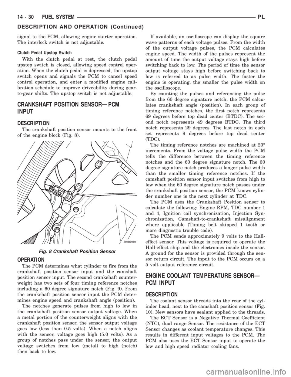
The crankshaft position sensor mounts to the front
of the engine block (Fig. 8).
OPERATION
The PCM determines what cylinder to fire from the
crankshaft position sensor input and the camshaft
position sensor input. The second crankshaft counter-
weight has two sets of four timing reference notches
including a 60 degree signature notch (Fig. 9). From
the crankshaft position sensor input the PCM deter-
mines engine speed and crankshaft angle (position).
The notches generate pulses from high to low in
the crankshaft position sensor output voltage. When
a metal portion of the counterweight aligns with the
crankshaft position sensor, the sensor output voltage
goes low (less than 0.5 volts). When a notch aligns
with the sensor, voltage goes high (5.0 volts). As a
group of notches pass under the sensor, the output
voltage switches from low (metal) to high (notch)
then back to low.If available, an oscilloscope can display the square
wave patterns of each voltage pulses. From the width
of the output voltage pulses, the PCM calculates
engine speed. The width of the pulses represent the
amount of time the output voltage stays high before
switching back to low. The period of time the sensor
output voltage stays high before switching back to
low is referred to as pulse width. The faster the
engine is operating, the smaller the pulse width on
the oscilloscope.
By counting the pulses and referencing the pulse
from the 60 degree signature notch, the PCM calcu-
lates crankshaft angle (position). In each group of
timing reference notches, the first notch represents
69 degrees before top dead center (BTDC). The sec-
ond notch represents 49 degrees BTDC. The third
notch represents 29 degrees. The last notch in each
set represents 9 degrees before top dead center
(TDC).
The timing reference notches are machined at 20É
increments. From the voltage pulse width the PCM
tells the difference between the timing reference
notches and the 60 degree signature notch. The 60
degree signature notch produces a longer pulse width
than the smaller timing reference notches. If the
camshaft position sensor input switches from high to
low when the 60 degree signature notch passes under
the crankshaft position sensor, the PCM knows cylin-
der number one is the next cylinder at TDC.
The PCM uses the Crankshaft Position sensor to
calculate the following: Engine RPM, TDC number 1
and 4, Ignition coil synchronization, Injection Syn-
chronization, Camshaft-to-crankshaft misalignment
where applicable (Timing belt skipped 1 tooth or
more diagnostic trouble code).
The PCM sends approximately 9 volts to the Hall-
effect sensor. This voltage is required to operate the
Hall-effect chip and the electronics inside the sensor.
A ground for the sensor is provided through the sen-
sor return circuit. The input to the PCM occurs on a
5 volt output reference circuit.
ENGINE COOLANT TEMPERATURE SENSORÐ
PCM INPUT
DESCRIPTION
The coolant sensor threads into the rear of the cyl-
inder head, next to the camshaft position sensor (Fig.
10). New sensors have sealant applied to the threads.
The ECT Sensor is a Negative Thermal Coefficient
(NTC), dual range Sensor. The resistance of the ECT
Sensor changes as coolant temperature changes. This
results in different input voltages to the PCM. The
PCM also uses the ECT Sensor input to operate the
low and high speed radiator cooling fans.
Fig. 8 Crankshaft Position Sensor
14 - 30 FUEL SYSTEMPL
DESCRIPTION AND OPERATION (Continued)
Page 856 of 1285
OPERATION
When the knock sensor detects a knock in one of
the cylinders, it sends an input signal to the PCM. In
response, the PCM retards ignition timing for all cyl-
inders by a scheduled amount.
Knock sensors contain a piezoelectric material
which sends an input voltage (signal) to the PCM. As
the intensity of the engine knock vibration increases,
the knock sensor output voltage also increases.
The voltage signal produced by the knock sensor
increases with the amplitude of vibration. The PCM
receives as an input the knock sensor voltage signal.
If the signal rises above a predetermined level, the
PCM will store that value in memory and retard
ignition timing to reduce engine knock. If the knock
sensor voltage exceeds a preset value, the PCM
retards ignition timing for all cylinders. It is not a
selective cylinder retard.
The PCM ignores knock sensor input during engine
idle conditions. Once the engine speed exceeds a
specified value, knock retard is allowed.
Knock retard uses its own short term and long
term memory program.
Long term memory stores previous detonation
information in its battery-backed RAM. The maxi-
mum authority that long term memory has over tim-
ing retard can be calibrated.
Short term memory is allowed to retard timing up
to a preset amount under all operating conditions (as
long as rpm is above the minimum rpm) except WOT.
The PCM, using short term memory, can respond
quickly to retard timing when engine knock is
detected. Short term memory is lost any time the
ignition key is turned off.
MANIFOLD ABSOLUTE PRESSURE (MAP)
SENSORÐPCM INPUT
DESCRIPTION
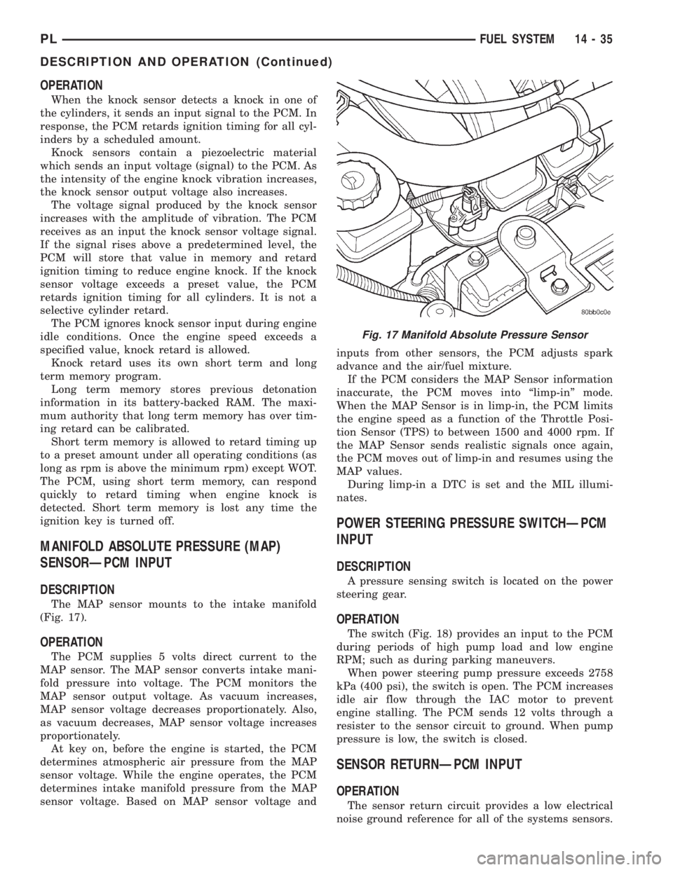
The MAP sensor mounts to the intake manifold
(Fig. 17).
OPERATION
The PCM supplies 5 volts direct current to the
MAP sensor. The MAP sensor converts intake mani-
fold pressure into voltage. The PCM monitors the
MAP sensor output voltage. As vacuum increases,
MAP sensor voltage decreases proportionately. Also,
as vacuum decreases, MAP sensor voltage increases
proportionately.
At key on, before the engine is started, the PCM
determines atmospheric air pressure from the MAP
sensor voltage. While the engine operates, the PCM
determines intake manifold pressure from the MAP
sensor voltage. Based on MAP sensor voltage andinputs from other sensors, the PCM adjusts spark
advance and the air/fuel mixture.
If the PCM considers the MAP Sensor information
inaccurate, the PCM moves into ªlimp-inº mode.
When the MAP Sensor is in limp-in, the PCM limits
the engine speed as a function of the Throttle Posi-
tion Sensor (TPS) to between 1500 and 4000 rpm. If
the MAP Sensor sends realistic signals once again,
the PCM moves out of limp-in and resumes using the
MAP values.
During limp-in a DTC is set and the MIL illumi-
nates.
POWER STEERING PRESSURE SWITCHÐPCM
INPUT
DESCRIPTION
A pressure sensing switch is located on the power
steering gear.
OPERATION
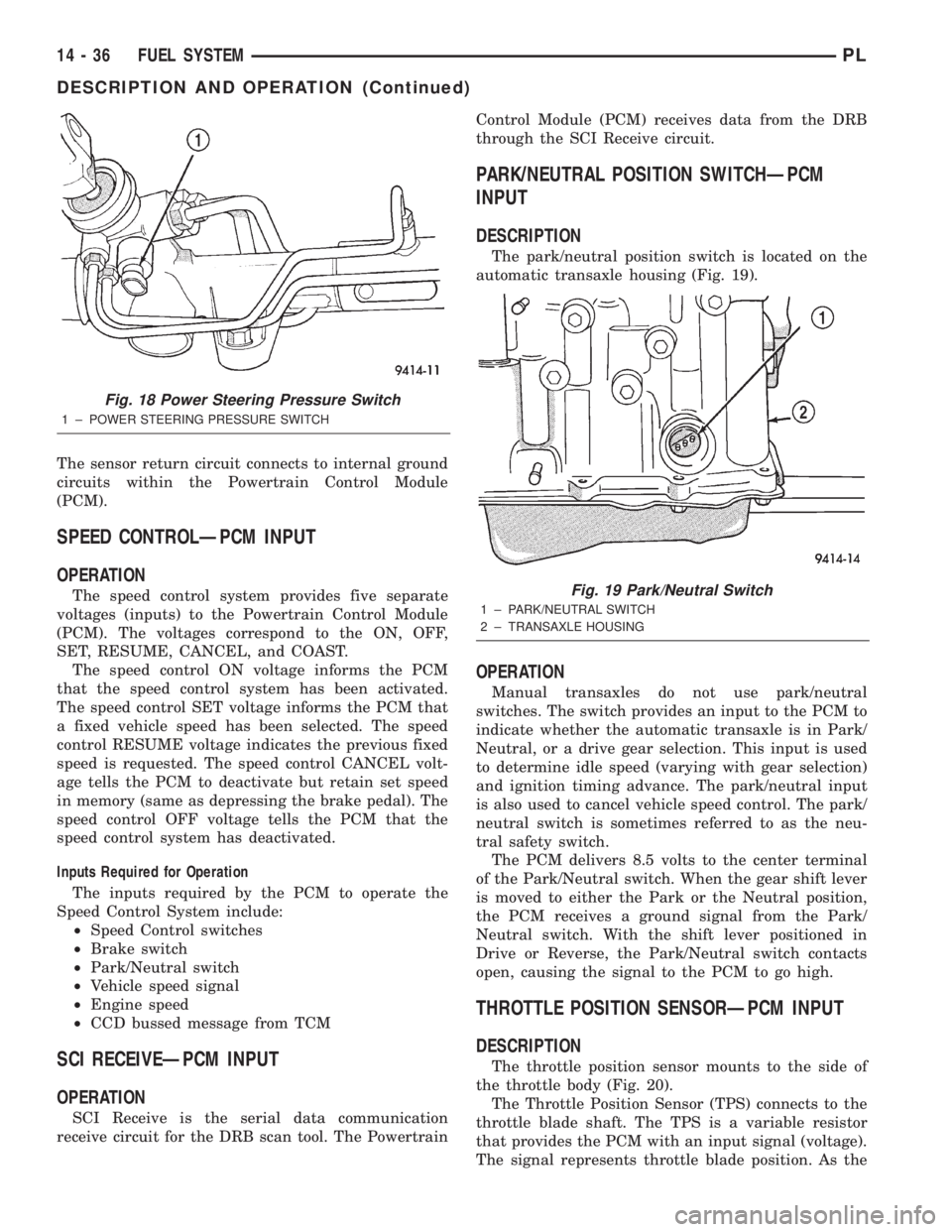
The switch (Fig. 18) provides an input to the PCM
during periods of high pump load and low engine
RPM; such as during parking maneuvers.
When power steering pump pressure exceeds 2758
kPa (400 psi), the switch is open. The PCM increases
idle air flow through the IAC motor to prevent
engine stalling. The PCM sends 12 volts through a
resister to the sensor circuit to ground. When pump
pressure is low, the switch is closed.
SENSOR RETURNÐPCM INPUT
OPERATION
The sensor return circuit provides a low electrical
noise ground reference for all of the systems sensors.
Fig. 17 Manifold Absolute Pressure Sensor
PLFUEL SYSTEM 14 - 35
DESCRIPTION AND OPERATION (Continued)
Page 857 of 1285
The sensor return circuit connects to internal ground
circuits within the Powertrain Control Module
(PCM).
SPEED CONTROLÐPCM INPUT
OPERATION
The speed control system provides five separate
voltages (inputs) to the Powertrain Control Module
(PCM). The voltages correspond to the ON, OFF,
SET, RESUME, CANCEL, and COAST.
The speed control ON voltage informs the PCM
that the speed control system has been activated.
The speed control SET voltage informs the PCM that
a fixed vehicle speed has been selected. The speed
control RESUME voltage indicates the previous fixed
speed is requested. The speed control CANCEL volt-
age tells the PCM to deactivate but retain set speed
in memory (same as depressing the brake pedal). The
speed control OFF voltage tells the PCM that the
speed control system has deactivated.
Inputs Required for Operation
The inputs required by the PCM to operate the
Speed Control System include:
²Speed Control switches
²Brake switch
²Park/Neutral switch
²Vehicle speed signal
²Engine speed
²CCD bussed message from TCM
SCI RECEIVEÐPCM INPUT
OPERATION
SCI Receive is the serial data communication
receive circuit for the DRB scan tool. The PowertrainControl Module (PCM) receives data from the DRB
through the SCI Receive circuit.
PARK/NEUTRAL POSITION SWITCHÐPCM
INPUT
DESCRIPTION
The park/neutral position switch is located on the
automatic transaxle housing (Fig. 19).
OPERATION
Manual transaxles do not use park/neutral
switches. The switch provides an input to the PCM to
indicate whether the automatic transaxle is in Park/
Neutral, or a drive gear selection. This input is used
to determine idle speed (varying with gear selection)
and ignition timing advance. The park/neutral input
is also used to cancel vehicle speed control. The park/
neutral switch is sometimes referred to as the neu-
tral safety switch.
The PCM delivers 8.5 volts to the center terminal
of the Park/Neutral switch. When the gear shift lever
is moved to either the Park or the Neutral position,
the PCM receives a ground signal from the Park/
Neutral switch. With the shift lever positioned in
Drive or Reverse, the Park/Neutral switch contacts
open, causing the signal to the PCM to go high.
THROTTLE POSITION SENSORÐPCM INPUT
DESCRIPTION
The throttle position sensor mounts to the side of
the throttle body (Fig. 20).
The Throttle Position Sensor (TPS) connects to the
throttle blade shaft. The TPS is a variable resistor
that provides the PCM with an input signal (voltage).
The signal represents throttle blade position. As the
Fig. 18 Power Steering Pressure Switch
1 ± POWER STEERING PRESSURE SWITCH
Fig. 19 Park/Neutral Switch
1 ± PARK/NEUTRAL SWITCH
2 ± TRANSAXLE HOUSING
14 - 36 FUEL SYSTEMPL
DESCRIPTION AND OPERATION (Continued)
Page 903 of 1285
REMOVAL
(1) Disconnect the negative (-) cable from the bat-
tery and isolate the cable.
(2) Before beginning removal of the steering col-
umn, be sure the front wheels of vehicle are in the
STRAIGHT-AHEAD position.
(3) Remove the screw securing the left end of the
top cover to the instrument panel. It is located just
above the left instrument panel end cap.
(4) Starting on the driver's end, push upward on
the instrument panel top cover, disengaging its
retainer clips along the face of the instrument panel.
Disengage just enough clips to allow access to the
upper ends of the instrument cluster bezel.
(5) Disengage the clips along the outer edge of the
instrument cluster bezel and remove the bezel from
the vehicle.
(6) Remove the two screws along the bottom of the
steering column cover that mounts below the steering
column on the instrument panel. Disengage the clips
on the upper end of the steering column cover and
remove the cover by pulling it straight away from the
instrument panel.
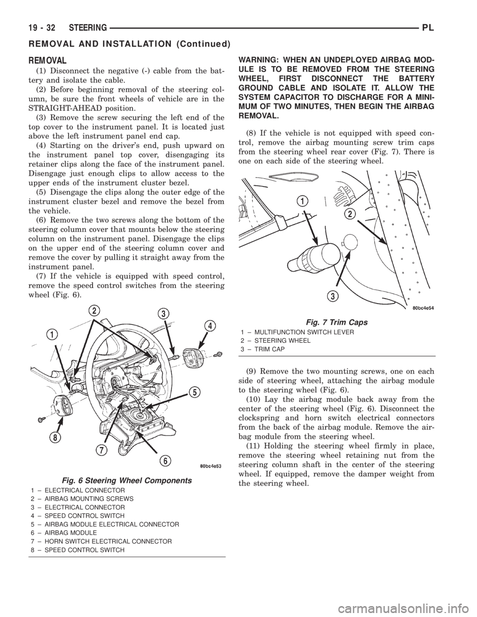
(7) If the vehicle is equipped with speed control,
remove the speed control switches from the steering
wheel (Fig. 6).WARNING: WHEN AN UNDEPLOYED AIRBAG MOD-
ULE IS TO BE REMOVED FROM THE STEERING
WHEEL, FIRST DISCONNECT THE BATTERY
GROUND CABLE AND ISOLATE IT. ALLOW THE
SYSTEM CAPACITOR TO DISCHARGE FOR A MINI-
MUM OF TWO MINUTES, THEN BEGIN THE AIRBAG
REMOVAL.
(8) If the vehicle is not equipped with speed con-
trol, remove the airbag mounting screw trim caps
from the steering wheel rear cover (Fig. 7). There is
one on each side of the steering wheel.
(9) Remove the two mounting screws, one on each
side of steering wheel, attaching the airbag module
to the steering wheel (Fig. 6).
(10) Lay the airbag module back away from the
center of the steering wheel (Fig. 6). Disconnect the
clockspring and horn switch electrical connectors
from the back of the airbag module. Remove the air-
bag module from the steering wheel.
(11) Holding the steering wheel firmly in place,
remove the steering wheel retaining nut from the
steering column shaft in the center of the steering
wheel. If equipped, remove the damper weight from
the steering wheel.
Fig. 6 Steering Wheel Components
1 ± ELECTRICAL CONNECTOR
2 ± AIRBAG MOUNTING SCREWS
3 ± ELECTRICAL CONNECTOR
4 ± SPEED CONTROL SWITCH
5 ± AIRBAG MODULE ELECTRICAL CONNECTOR
6 ± AIRBAG MODULE
7 ± HORN SWITCH ELECTRICAL CONNECTOR
8 ± SPEED CONTROL SWITCH
Fig. 7 Trim Caps
1 ± MULTIFUNCTION SWITCH LEVER
2 ± STEERING WHEEL
3 ± TRIM CAP
19 - 32 STEERINGPL
REMOVAL AND INSTALLATION (Continued)
Page 908 of 1285
bolt nut to a torque of 28 N´m (250 in. lbs.). Install
the pinch bolt retainer pin.
(11) Install the upper and lower steering column
shrouds onto the steering column (Fig. 9). Snap the
two shrouds together and then install and tighten
the two screws securing the shrouds to the column.
(12) Install the steering column cover that mounts
below the steering column on the instrument panel
by first aligning the retainer clips and snapping the
cover into place. Install the two screws along the bot-
tom of the steering column cover.
(13) Align the clips along the outer edge of the
instrument cluster bezel with the mounting holes in
the instrument panel and install the bezel.
(14) Align the clips on the bottom of the instru-
ment panel top cover with the mounting holes in the
instrument panel and install the top cover by push-
ing it down into place.
(15) Install the screw securing the left end of the
top cover to the instrument panel.
CAUTION: If there is any question as to whether
the clockspring is in the centered position, the
clock spring needs to be recentered before install-
ing the steering wheel. If the clockspring is not cen-
tered, it may be overextended, causing the
clockspring to become inoperative.
(16) Center the clockspring using the following
procedure:
²Using your fingers, rotate the clockspring rotor
in the CLOCKWISE DIRECTION to the end of the
travel. Do not apply excessive torque.
²From the end of travel, rotate the rotor two full
turns and an additional half turn in the counter-
clockwise direction. (The wires should end up at the
bottom of the clockspring).
CAUTION: Do not install the steering wheel onto
the shaft of the steering column by driving it onto
the shaft.
(17) Feed the clockspring wiring leads through the
hole in the steering wheel (Fig. 6). Align the steering
wheel's wide mounting spline with the steering col-
umn shaft missing spline area and push the wheel
onto the shaft. Make sure the clockspring squares up
with the back of the wheel and does not bind.
(18) Install the steering wheel retaining nut and
tighten it until the steering wheel is fully installed
on shaft. Tighten the steering wheel retaining nut to
a torque of 61 N´m (45 ft. lbs.).
(19) Connect the clockspring electrical leads to the
speed control switches and reinstall the switches on
the steering wheel (Fig. 6).
(20) Install the airbag electrical lead from the
clockspring into the connector on the back of the air-bag module (Fig. 6). Be sure electrical connector from
clockspring is securely latched into airbag module
connector.
(21) Connect the horn switch electrical lead to the
connector on the back of the airbag module (Fig. 6).
CAUTION: The fasteners originally used for the air-
bag components are specifically designed for the
airbag system. They must never be replaced with
any substitutes. Anytime a new fastener is needed,
replace it with only the correct fastener listed in the
parts book.
(22) Install the airbag module into the center of
the steering wheel. Align the airbag module mount-
ing holes with the bolt holes in steering wheel (Fig.
6). Install only the two original or identical replace-
ment airbag module mounting screws. Tighten the
two air bag module attaching bolts to a torque of 10
N´m (90 in. lbs.).
(23) Install the airbag mounting screw trim caps
on the steering wheel rear cover (Fig. 7). One belongs
on each side of the steering wheel.
NOTE: When reconnecting the battery on a vehicle
that has had the airbag module removed, the fol-
lowing procedure should be used.
(24) Reconnect the ground cable to the negative
post of the battery in the following manor:
²Connect a scan tool (DRBIIIt) to the data link
diagnostic connector located below the steering col-
umn.
²Turn the ignition key to the ON position. Exit
the vehicle with the scan tool leaving the scan tool
harness plugged in.
²Ensuring that there are no occupants in the
vehicle, connect the ground (-) cable to the negative
post of the battery.
²Using the scan tool, read and record any fault
codes. Refer to the DRIVER AND PASSENGER AIR-
BAG SYSTEM diagnostic manual if any faults are
found.
²Erase any stored faults if there are no active
fault codes. If a problem exists, the fault code will
not erase.
²Reach around the back of the steering wheel (in
front of the instrument cluster) and turn the ignition
key to OFF, then back ON while observing the
instrument cluster airbag lamp. It should go on for
six to eight seconds, then go out. This will indicate
that the airbag system is functioning normally. If air-
bag warning lamp fails to light, blinks on and off, or
goes on and stays on, there is an airbag system mal-
function. Refer to the BODY DIAGNOSTIC PROCE-
DURES manual to diagnose the system malfunction.
PLSTEERING 19 - 37
REMOVAL AND INSTALLATION (Continued)
Page 1235 of 1285
SAFETY PRECAUTIONS AND WARNINGS
WARNING: WEAR EYE PROTECTION WHEN SER-
VICING THE AIR CONDITIONING REFRIGERANT
SYSTEM. SERIOUS EYE INJURY CAN RESULT
FROM EYE CONTACT WITH REFRIGERANT. IF EYE
CONTACT IS MADE, SEEK MEDICAL ATTENTION
IMMEDIATELY.
DO NOT EXPOSE REFRIGERANT TO OPEN
FLAME. POISONOUS GAS IS CREATED WHEN
REFRIGERANT IS BURNED. AN ELECTRONIC TYPE
LEAK DETECTOR IS RECOMMENDED.
LARGE AMOUNTS OF REFRIGERANT RELEASED
IN A CLOSED WORK AREA WILL DISPLACE THE
OXYGEN AND CAUSE SUFFOCATION.
THE EVAPORATION RATE OF REFRIGERANT AT
AVERAGE TEMPERATURE AND ALTITUDE IS
EXTREMELY HIGH. AS A RESULT, ANYTHING THAT
COMES IN CONTACT WITH THE REFRIGERANT
WILL FREEZE. ALWAYS PROTECT SKIN OR DELI-
CATE OBJECTS FROM DIRECT CONTACT WITH
REFRIGERANT. R-134a SERVICE EQUIPMENT OR
VEHICLE A/C SYSTEM SHOULD NOT BE PRES-
SURE TESTED OR LEAK TESTED WITH COM-
PRESSED AIR.
SOME MIXTURES OF AIR and R-134a HAVE BEEN
SHOWN TO BE COMBUSTIBLE AT ELEVATED
PRESSURES. THESE MIXTURES ARE POTENTIALLY
DANGEROUS AND MAY RESULT IN FIRE OR
EXPLOSION CAUSING INJURY OR PROPERTY
DAMAGE.
ANTIFREEZE IS AN ETHYLENE GLYCOL BASE
COOLANT AND IS HARMFUL IF SWALLOWED OR
INHALED. SEEK MEDICAL ATTENTION IMMEDI-
ATELY IF SWALLOWED OR INHALED. DO NOT
STORE IN OPEN OR UNMARKED CONTAINERS.
WASH SKIN AND CLOTHING THOROUGHLY AFTER
COMING IN CONTACT WITH ETHYLENE GLYCOL.
KEEP OUT OF REACH OF CHILDREN AND PETS.
DO NOT OPEN A COOLING SYSTEM WHEN THE
ENGINE IS AT RUNNING TEMPERATURE. PER-
SONAL INJURY CAN RESULT.
CAUTION: The engine cooling system is designed
to develop internal pressure of 97 to 123 kPa (14 to
18 psi). Allow the vehicle to cool a minimum of 15
minutes before opening the cooling system. Refer
to Group 7, Cooling System.
DESCRIPTION AND OPERATION
A/C REFRIGERANT LINES
DISCHARGE LINE
The discharge line is the line that goes from the
compressor to the condenser (Fig. 3). It has no ser-
viceable parts except the rubber O-rings. If the line
is found to be leaking or is damaged it must be
replaced as an assembly.
LIQUID LINE
The liquid line is the line that goes from the con-
denser to drier (Fig. 3). It has no serviceable parts
except the rubber O-rings. If the line is found to be
leaking or is damaged it must be replaced as an
assembly.
SUCTION LINE
The suction line is the large line that connects to
the expansion valve and goes to the compressor (Fig.
3). It also has a small line that goes to the filter/
drier. The suction line uses a gasket on the expan-
sion valve side and rubber O-rings on all other
connections.
There are no serviceable parts on the suction line
other than the rubber O-rings and expansion valve
gasket. If the line is found to be leaking or is dam-
aged it must be replaced as an assembly.
Fig. 3 A/C Compressor Lines
1 ± CONDENSER LIQUID LINE
2 ± SUCTION LINE
3 ± COMPRESSOR MANIFOLD SCREWS
4 ± COMPRESSOR
5 ± DISCHARGE LINE
24 - 4 HEATING AND AIR CONDITIONINGPL
GENERAL INFORMATION (Continued)
Page 1237 of 1285
COMPRESSOR FRONT SHAFT SEAL
The compressor front shaft seal is not serviceable.
If a leak is detected at the shaft seal, the compressor
must be replaced as a unit.
CONDENSATION DRAIN TUBE
Condensation that accumulates in the evaporator
housing is drained from a tube through the dash and
on to the ground. This tube must be kept open to
prevent condensate water from collecting in the bot-
tom of the housing.
The tapered end of the drain tube is designed to
keep contaminants from entering the heater A/C unit
housing. If the tube is pinched or blocked, condensate
cannot drain, causing water to back up and spill into
the passenger compartment. It is normal to see con-
densate drainage below the vehicle. If the tube is
damaged, it should be replaced.
ENGINE COOLING SYSTEM REQUIREMENTS
To maintain ample temperature levels from the
heating-A/C system, the cooling system must be in
proper working order. Refer to Group 0, Lubrication
and Maintenance or Group 7, Cooling System of this
manual.
The use of a bug screen is not recommended. Any
obstructions forward of the condenser can reduce the
effectiveness of the air conditioning system.
EVAPORATOR PROBE
The evaporator probe can be replaced without hav-
ing to remove the unit housing from the vehicle.
The evaporator probe is located in the unit housing
and placed in the evaporator fins. The probe prevents
evaporator freeze-up. This is done by cycling the com-
pressor clutch OFF when evaporator temperature
drops below freeze point. It cycles ON when the
evaporator temperature rises above freeze point. The
evaporator probe uses a thermistor probe in a capil-
lary tube. The tube is inserted between the evapora-
tor fins in the heater-A/C unit housing.
HANDLING TUBING AND FITTINGS
Kinks in the refrigerant tubing or sharp bends in
the refrigerant hose lines will greatly reduce the
capacity of the entire system. High pressures are pro-
duced in the system when it is operating. Extreme
care must be exercised to make sure that all connec-
tions are pressure tight. Dirt and moisture can enter
the system when it is opened for repair or replace-
ment of lines or components. The refrigerant oil will
absorb moisture readily out of the air. This moisture
will convert into acids within a closed system.CAUTION: The system must be completely empty
before opening any fitting or connection in the
refrigeration system. Open fittings with caution
even after the system has been emptied. If any
pressure is noticed as a fitting is loosened,
retighten fitting and evacuate the system again.
A good rule for the flexible hose lines is to keep
the radius of all bends at least 10 times the diame-
ter of the hose. Sharper bends will reduce the flow
of refrigerant. The flexible hose lines should be
routed so they are at least 3 inches (80 mm) from
the exhaust manifold. Inspect all flexible hose lines
to make sure they are in good condition and prop-
erly routed.
The use of correct wrenches when making con-
nections is very important. Improper wrenches or
improper use of wrenches can damage the fittings.
The internal parts of the A/C system will remain
stable as long as moisture-free refrigerant and
refrigerant oil is used. Abnormal amounts of dirt,
moisture or air can upset the chemical stability.
This may cause operational troubles or even seri-
ous damage if present in more than very small
quantities.
When opening a refrigeration system, have every-
thing you will need to repair the system ready. This
will minimize the amount of time the system must
be opened. Cap or plug all lines and fittings as
soon as they are opened. This will help prevent the
entrance of dirt and moisture. All new lines and
components should be capped or sealed until they
are ready to be used.
All tools, including the refrigerant dispensing
manifold, the manifold gauge set, and test hoses
should be kept clean and dry.
HIGH PRESSURE CUT OUT SWITCH
The high pressure cut out switch is located on the
rear of the compressor (Fig. 7). It turns off the com-
pressor if the system pressure exceeds 3240 kPa (470
psi).
LOW PRESSURE CUT OFF SWITCH
The Low Pressure Cut Off Switch (Fig. 8) monitors
the refrigerant gas pressure on the suction side of
the system. The low pressure cut off switch is located
on the expansion valve. The low pressure cut off
switch turns off voltage to the compressor clutch coil
when refrigerant gas pressure drops to levels that
could damage the compressor. The low pressure cut
out switch is a sealed factory calibrated unit. It must
be replaced if defective.
24 - 6 HEATING AND AIR CONDITIONINGPL
DESCRIPTION AND OPERATION (Continued)
Page 1242 of 1285
BLOWER MOTOR VIBRATION AND/OR NOISE
DIAGNOSIS
The resistor block supplies the blower motor with
varied voltage (low and middle speeds) or battery
voltage (high speed).
CAUTION: Stay clear of the blower motor and resis-
tor block (Hot). Do not operate the blower motor
with the resistor block removed from the heater-A/C
housing.
Refer to the Blower Motor Vibration/Noise chart
for diagnosis.
COMPRESSOR NOISE DIAGNOSIS
Excessive noise while the A/C is being used, can be
caused by loose mounts, loose clutch, or high operat-
ing pressure. Verify compressor drive belt condition,
proper refrigerant charge and head pressure before
compressor repair is performed.
If the A/C drive belt slips at initial start-up, it does
not necessarily mean the compressor has failed.
With the close tolerances of a compressor it is pos-
sible to experience a temporary lockup. The longer
the A/C system is inactive, the more likely the condi-
tion to occur.
This condition is the result of normal refrigerant
movement within the A/C system caused by temper-
ature changes. The refrigerant movement may wash
the oil out of the compressor.
EVAPORATOR PROBE TEST
The work area and vehicle must be between 16É C
(60É F) and 32É C (90É F) when testing the switch.
(1) Disconnect the three wire connector from the
evaporator probe lead located behind the glove box
(Fig. 12).
(2) Start engine and set A/C to low blower motor
speed, panel, full cool, and RECIRC.
(3) Using a voltmeter, check for battery voltage
between Pin 1 and 2. If no voltage is detected, there
is no power to the switch. Check wiring and fuses.
Refer to Group 8W, Wiring Diagrams for circuit diag-
nosis.
(4) Using a voltmeter, check for battery voltage
between Pin 1 and Pin 3. If no voltage is detected,
there is no voltage from the Powertrain Control Mod-
ule. Refer to Group 8W, Wiring Diagrams. If voltage
is OK, connect a jumper wire between Pin 1 and Pin
3. The compressor clutch should engage. If the clutch
engages, remove the jumper wire immediately and go
to Step 5. If the compressor clutch does not engage,
check the operation of the clutch and repair as nec-
essary.(5) If compressor clutch engages, connect the evap-
orator probe 3-way connector. The compressor clutch
should engage or cycle depending on evaporator tem-
perature. If OK, go to Step 6. If not OK, replace the
clutch cycling switch.
(6) The engine running and the A/C set to:
²Blower motor on low speed
²Panel position
²Full cool
²RECIRC.
Close all doors and windows. Place a thermometer in
the center discharge vent.
(7) If the clutch does not begin to cycle off between
2É C to 7É C (35É F to 45É F), verify that the evapo-
rator probe is fully installed and not loose in evapo-
rator. If it is not properly installed, install probe and
retest outlet temperature. If the evaporator probe is
properly installed, replace the clutch cycling switch.
EXPANSION VALVE
NOTE: Expansion valve tests should be performed
after compressor tests.
Liquid CO2 is required to test the expansion
valve. It is available from most welding supply facil-
ities. CO2 is also available from companies which
service and sell fire extinguishers.
Review Safety Precautions and Warnings in the
General Information section of this Group. The work
area and vehicle must be 21É to 27ÉC (70É to 85ÉF)
when testing expansion valve. To test the expansion
valve:
(1) Connect a charging station or manifold gauge
set to the refrigerant system service ports.
(2) Disconnect wire connector at low pressure cut-
off switch (Fig. 13). Using a jumper wire, jump ter-
minals inside wire connector boot.
(3) Close all doors, windows and vents to the pas-
senger compartment.
(4) Set Heater-A/C control to A/C, full heat, floor,
RECIRC. and high blower.
(5) Start the engine and hold the idle speed (1000
rpm). After the engine has reached running temper-
ature, allow the passenger compartment to heat up.
This will create the need for maximum refrigerant
flow into the evaporator.
(6) If the refrigerant charge is sufficient, discharge
(high pressure) gauge should read 965 to 2620 kPa
(140 to 380 psi). Suction (low pressure) gauge should
read 103 to 2417 kPa (15 to 35 psi). If system cannot
achieve proper pressure readings, replace the expan-
sion valve. If pressure is correct, proceed with test.
PLHEATING AND AIR CONDITIONING 24 - 11
DIAGNOSIS AND TESTING (Continued)