2000 DODGE NEON mounts
[x] Cancel search: mountsPage 200 of 1285
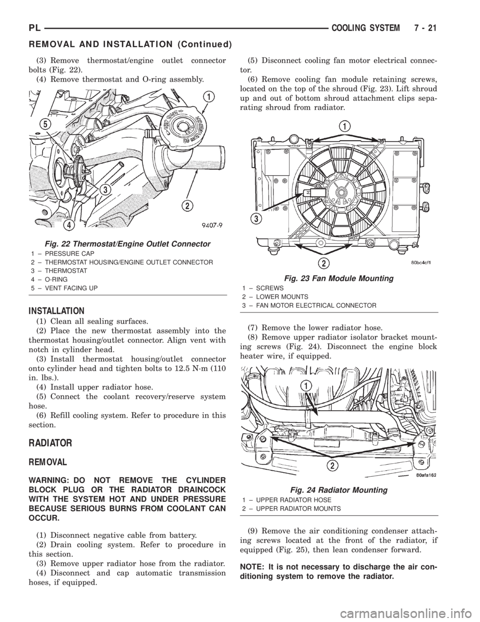
(3) Remove thermostat/engine outlet connector
bolts (Fig. 22).
(4) Remove thermostat and O-ring assembly.
INSTALLATION
(1) Clean all sealing surfaces.
(2) Place the new thermostat assembly into the
thermostat housing/outlet connector. Align vent with
notch in cylinder head.
(3) Install thermostat housing/outlet connector
onto cylinder head and tighten bolts to 12.5 N´m (110
in. lbs.).
(4) Install upper radiator hose.
(5) Connect the coolant recovery/reserve system
hose.
(6) Refill cooling system. Refer to procedure in this
section.
RADIATOR
REMOVAL
WARNING: DO NOT REMOVE THE CYLINDER
BLOCK PLUG OR THE RADIATOR DRAINCOCK
WITH THE SYSTEM HOT AND UNDER PRESSURE
BECAUSE SERIOUS BURNS FROM COOLANT CAN
OCCUR.
(1) Disconnect negative cable from battery.
(2) Drain cooling system. Refer to procedure in
this section.
(3) Remove upper radiator hose from the radiator.
(4) Disconnect and cap automatic transmission
hoses, if equipped.(5) Disconnect cooling fan motor electrical connec-
tor.
(6) Remove cooling fan module retaining screws,
located on the top of the shroud (Fig. 23). Lift shroud
up and out of bottom shroud attachment clips sepa-
rating shroud from radiator.
(7) Remove the lower radiator hose.
(8) Remove upper radiator isolator bracket mount-
ing screws (Fig. 24). Disconnect the engine block
heater wire, if equipped.
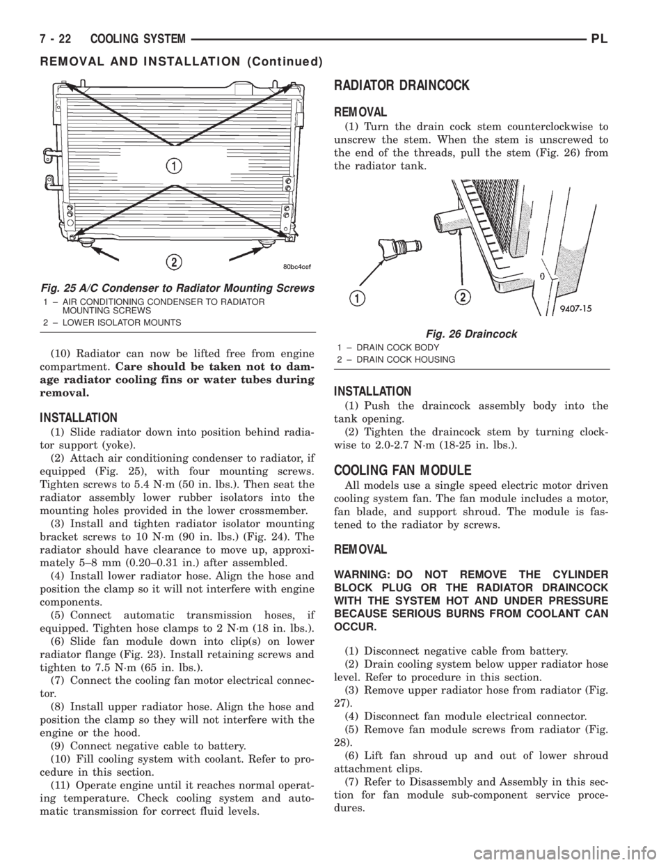
(9) Remove the air conditioning condenser attach-
ing screws located at the front of the radiator, if
equipped (Fig. 25), then lean condenser forward.
NOTE: It is not necessary to discharge the air con-
ditioning system to remove the radiator.
Fig. 22 Thermostat/Engine Outlet Connector
1 ± PRESSURE CAP
2 ± THERMOSTAT HOUSING/ENGINE OUTLET CONNECTOR
3 ± THERMOSTAT
4 ± O-RING
5 ± VENT FACING UP
Fig. 23 Fan Module Mounting
1 ± SCREWS
2 ± LOWER MOUNTS
3 ± FAN MOTOR ELECTRICAL CONNECTOR
Fig. 24 Radiator Mounting
1 ± UPPER RADIATOR HOSE
2 ± UPPER RADIATOR MOUNTS
PLCOOLING SYSTEM 7 - 21
REMOVAL AND INSTALLATION (Continued)
Page 201 of 1285
(10) Radiator can now be lifted free from engine
compartment.Care should be taken not to dam-
age radiator cooling fins or water tubes during
removal.
INSTALLATION
(1) Slide radiator down into position behind radia-
tor support (yoke).
(2) Attach air conditioning condenser to radiator, if
equipped (Fig. 25), with four mounting screws.
Tighten screws to 5.4 N´m (50 in. lbs.). Then seat the
radiator assembly lower rubber isolators into the
mounting holes provided in the lower crossmember.
(3) Install and tighten radiator isolator mounting
bracket screws to 10 N´m (90 in. lbs.) (Fig. 24). The
radiator should have clearance to move up, approxi-
mately 5±8 mm (0.20±0.31 in.) after assembled.
(4) Install lower radiator hose. Align the hose and
position the clamp so it will not interfere with engine
components.
(5) Connect automatic transmission hoses, if
equipped. Tighten hose clamps to 2 N´m (18 in. lbs.).
(6) Slide fan module down into clip(s) on lower
radiator flange (Fig. 23). Install retaining screws and
tighten to 7.5 N´m (65 in. lbs.).
(7) Connect the cooling fan motor electrical connec-
tor.
(8) Install upper radiator hose. Align the hose and
position the clamp so they will not interfere with the
engine or the hood.
(9) Connect negative cable to battery.
(10) Fill cooling system with coolant. Refer to pro-
cedure in this section.
(11) Operate engine until it reaches normal operat-
ing temperature. Check cooling system and auto-
matic transmission for correct fluid levels.
RADIATOR DRAINCOCK
REMOVAL
(1) Turn the drain cock stem counterclockwise to
unscrew the stem. When the stem is unscrewed to
the end of the threads, pull the stem (Fig. 26) from
the radiator tank.
INSTALLATION
(1) Push the draincock assembly body into the
tank opening.
(2) Tighten the draincock stem by turning clock-
wise to 2.0-2.7 N´m (18-25 in. lbs.).
COOLING FAN MODULE
All models use a single speed electric motor driven
cooling system fan. The fan module includes a motor,
fan blade, and support shroud. The module is fas-
tened to the radiator by screws.
REMOVAL
WARNING: DO NOT REMOVE THE CYLINDER
BLOCK PLUG OR THE RADIATOR DRAINCOCK
WITH THE SYSTEM HOT AND UNDER PRESSURE
BECAUSE SERIOUS BURNS FROM COOLANT CAN
OCCUR.
(1) Disconnect negative cable from battery.
(2) Drain cooling system below upper radiator hose
level. Refer to procedure in this section.
(3) Remove upper radiator hose from radiator (Fig.
27).
(4) Disconnect fan module electrical connector.
(5) Remove fan module screws from radiator (Fig.
28).
(6) Lift fan shroud up and out of lower shroud
attachment clips.
(7) Refer to Disassembly and Assembly in this sec-
tion for fan module sub-component service proce-
dures.
Fig. 25 A/C Condenser to Radiator Mounting Screws
1 ± AIR CONDITIONING CONDENSER TO RADIATOR
MOUNTING SCREWS
2 ± LOWER ISOLATOR MOUNTS
Fig. 26 Draincock
1 ± DRAIN COCK BODY
2 ± DRAIN COCK HOUSING
7 - 22 COOLING SYSTEMPL
REMOVAL AND INSTALLATION (Continued)
Page 202 of 1285
INSTALLATION
(1) Install the fan module into the clips on the
lower radiator tank.
(2) Install the fan module retaining screws and
tighten to 7.5 N´m (65 in. lbs.).
(3) Connect fan module electrical connector.For
wiring diagrams of fan motor systems, refer to
Group 8W, Wiring Diagrams.
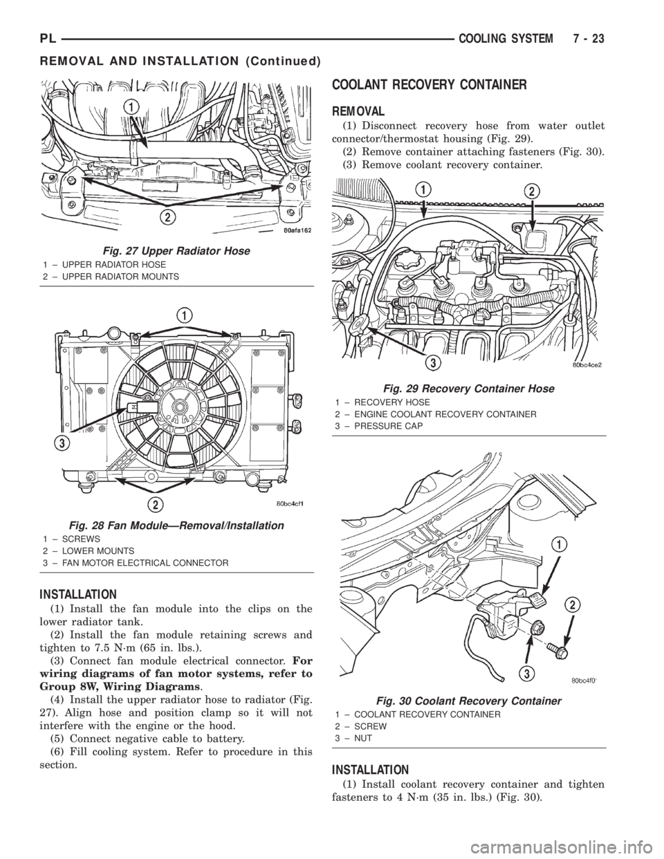
(4) Install the upper radiator hose to radiator (Fig.
27). Align hose and position clamp so it will not
interfere with the engine or the hood.
(5) Connect negative cable to battery.
(6) Fill cooling system. Refer to procedure in this
section.
COOLANT RECOVERY CONTAINER
REMOVAL
(1) Disconnect recovery hose from water outlet
connector/thermostat housing (Fig. 29).
(2) Remove container attaching fasteners (Fig. 30).
(3) Remove coolant recovery container.
INSTALLATION
(1) Install coolant recovery container and tighten
fasteners to 4 N´m (35 in. lbs.) (Fig. 30).
Fig. 27 Upper Radiator Hose
1 ± UPPER RADIATOR HOSE
2 ± UPPER RADIATOR MOUNTS
Fig. 28 Fan ModuleÐRemoval/Installation
1 ± SCREWS
2 ± LOWER MOUNTS
3 ± FAN MOTOR ELECTRICAL CONNECTOR
Fig. 29 Recovery Container Hose
1 ± RECOVERY HOSE
2 ± ENGINE COOLANT RECOVERY CONTAINER
3 ± PRESSURE CAP
Fig. 30 Coolant Recovery Container
1 ± COOLANT RECOVERY CONTAINER
2 ± SCREW
3 ± NUT
PLCOOLING SYSTEM 7 - 23
REMOVAL AND INSTALLATION (Continued)
Page 238 of 1285
OPERATION
The Automatic Shutdown (ASD) relay supplies bat-
tery voltage to the fuel injectors, electronic ignition
coil and the heating elements in the oxygen sensors.
A buss bar in the Power Distribution Center (PDC)
supplies voltage to the solenoid side and contact side
of the relay. The fuse also protects the power circuit
for the fuel pump relay and pump. The fuse is
located in the PDC. Refer to the Wiring Diagrams for
circuit information.
The PCM controls the ASD relay by switching the
ground path for the solenoid side of the relay on and
off. The PCM turns the ground path off when the
ignition switch is in the Off position. When the igni-
tion switch is in On or Start, the PCM monitors the
crankshaft and camshaft position sensor signals to
determine engine speed and ignition timing (coil
dwell). If the PCM does not receive crankshaft and
camshaft position sensor signals when the ignition
switch is in the Run position, it will de-energize the
ASD relay.
CRANKSHAFT POSITION SENSORÐPCM
INPUT
DESCRIPTION
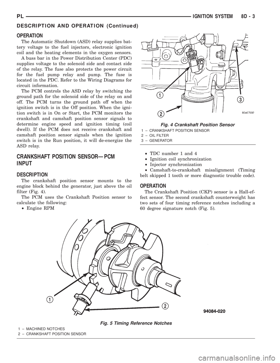
The crankshaft position sensor mounts to the
engine block behind the generator, just above the oil
filter (Fig. 4).
The PCM uses the Crankshaft Position sensor to
calculate the following:
²Engine RPM²TDC number 1 and 4
²Ignition coil synchronization
²Injector synchronization
²Camshaft-to-crankshaft misalignment (Timing
belt skipped 1 tooth or more diagnostic trouble code).
OPERATION
The Crankshaft Position (CKP) sensor is a Hall-ef-
fect sensor. The second crankshaft counterweight has
two sets of four timing reference notches including a
60 degree signature notch (Fig. 5).
Fig. 5 Timing Reference Notches
1 ± MACHINED NOTCHES
2 ± CRANKSHAFT POSITION SENSOR
Fig. 4 Crankshaft Position Sensor
1 ± CRANKSHAFT POSITION SENSOR
2 ± OIL FILTER
3 ± GENERATOR
PLIGNITION SYSTEM 8D - 3
DESCRIPTION AND OPERATION (Continued)
Page 243 of 1285
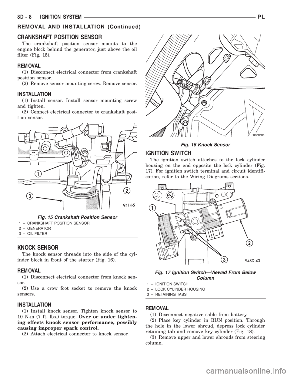
CRANKSHAFT POSITION SENSOR
The crankshaft position sensor mounts to the
engine block behind the generator, just above the oil
filter (Fig. 15).
REMOVAL
(1) Disconnect electrical connector from crankshaft
position sensor.
(2) Remove sensor mounting screw. Remove sensor.
INSTALLATION
(1) Install sensor. Install sensor mounting screw
and tighten.
(2) Connect electrical connector to crankshaft posi-
tion sensor.
KNOCK SENSOR
The knock sensor threads into the side of the cyl-
inder block in front of the starter (Fig. 16).
REMOVAL
(1) Disconnect electrical connector from knock sen-
sor.
(2) Use a crow foot socket to remove the knock
sensors.
INSTALLATION
(1) Install knock sensor. Tighten knock sensor to
10 N´m (7 ft. lbs.) torque.Over or under tighten-
ing effects knock sensor performance, possibly
causing improper spark control.
(2) Attach electrical connector to knock sensor.
IGNITION SWITCH
The ignition switch attaches to the lock cylinder
housing on the end opposite the lock cylinder (Fig.
17). For ignition switch terminal and circuit identifi-
cation, refer to the Wiring Diagrams sections.
REMOVAL
(1) Disconnect negative cable from battery.
(2) Place key cylinder in RUN position. Through
the hole in the lower shroud, depress lock cylinder
retaining tab and remove key cylinder (Fig. 18).
(3) Remove upper and lower shrouds from steering
column.
Fig. 15 Crankshaft Position Sensor
1 ± CRANKSHAFT POSITION SENSOR
2 ± GENERATOR
3 ± OIL FILTER
Fig. 16 Knock Sensor
Fig. 17 Ignition SwitchÐViewed From Below
Column
1 ± IGNITION SWITCH
2 ± LOCK CYLINDER HOUSING
3 ± RETAINING TABS
8D - 8 IGNITION SYSTEMPL
REMOVAL AND INSTALLATION (Continued)
Page 265 of 1285
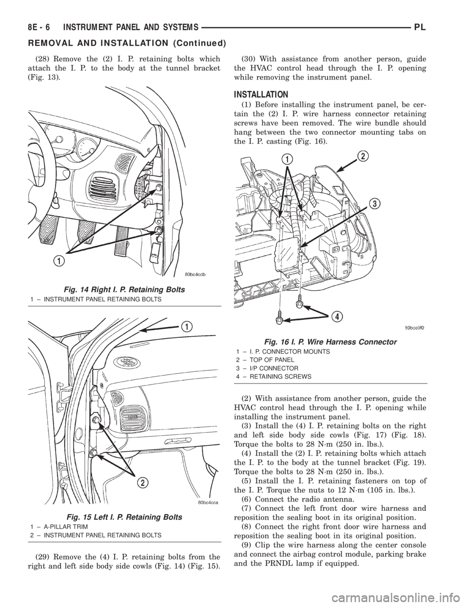
(28) Remove the (2) I. P. retaining bolts which
attach the I. P. to the body at the tunnel bracket
(Fig. 13).
(29) Remove the (4) I. P. retaining bolts from the
right and left side body side cowls (Fig. 14) (Fig. 15).(30) With assistance from another person, guide
the HVAC control head through the I. P. opening
while removing the instrument panel.
INSTALLATION
(1) Before installing the instrument panel, be cer-
tain the (2) I. P. wire harness connector retaining
screws have been removed. The wire bundle should
hang between the two connector mounting tabs on
the I. P. casting (Fig. 16).
(2) With assistance from another person, guide the
HVAC control head through the I. P. opening while
installing the instrument panel.
(3) Install the (4) I. P. retaining bolts on the right
and left side body side cowls (Fig. 17) (Fig. 18).
Torque the bolts to 28 N´m (250 in. lbs.).
(4) Install the (2) I. P. retaining bolts which attach
the I. P. to the body at the tunnel bracket (Fig. 19).
Torque the bolts to 28 N´m (250 in. lbs.).
(5) Install the I. P. retaining fasteners on top of
the I. P. Torque the nuts to 12 N´m (105 in. lbs.).
(6) Connect the radio antenna.
(7) Connect the left front door wire harness and
reposition the sealing boot in its original position.
(8) Connect the right front door wire harness and
reposition the sealing boot in its original position.
(9) Clip the wire harness along the center console
and connect the airbag control module, parking brake
and the PRNDL lamp if equipped.
Fig. 14 Right I. P. Retaining Bolts
1 ± INSTRUMENT PANEL RETAINING BOLTS
Fig. 15 Left I. P. Retaining Bolts
1 ± A-PILLAR TRIM
2 ± INSTRUMENT PANEL RETAINING BOLTS
Fig. 16 I. P. Wire Harness Connector
1 ± I. P. CONNECTOR MOUNTS
2 ± TOP OF PANEL
3 ± I/P CONNECTOR
4 ± RETAINING SCREWS
8E - 6 INSTRUMENT PANEL AND SYSTEMSPL
REMOVAL AND INSTALLATION (Continued)
Page 749 of 1285
(4) Discharge air conditioning system, if equipped.
Refer to Group 24, Heating and Air Conditioning for
procedure.
(5) Disconnect the following: air intake duct at
intake manifold, throttle cables, electrical connectors
from throttle body and air cleaner housing.
(6) Remove air cleaner housing assembly.
(7) Remove upper radiator hose and fan module.
Refer to Group 7, Cooling System for procedure.
(8) Remove lower radiator hose.
(9) Disconnect automatic transmission cooler lines
and plug, if equipped.
(10) Disconnect shift linkage, electrical connectors,
and clutch cable, if equipped with manual transaxle.
(11) Disconnect engine wiring harness.
(12) Disconnect positive cable from Power Distri-
bution Center (PDC) and ground wire from vehicle
body.
(13) Disconnect ground wire from the vehicle body-
to-engine at the right side strut tower.
(14) Disconnect heater hoses.
(15) Disconnect vacuum hose from brake booster.
(16) Disconnect coolant reserve/recovery hose.
(17) Remove accessory drive belts. Refer to Group
7, Cooling System for procedure.
(18) Remove power steering pump and reservoir
and set them aside.
(19) Hoist vehicle and remove right inner splash
shield.
(20) Drain engine oil.
(21) Remove front wheels.
(22) Remove axle shafts. Refer to Group 3, Differ-
ential and Driveline for procedure.
(23) Disconnect exhaust system from manifold.
(24) Disconnect the downstream oxygen sensor
connector.
(25) Remove lower engine torque strut.
(26) Remove structural collar. Refer to procedure
in this section.
(27) Lower vehicle and remove A/C compressor.
(28) Raise vehicle enough to allow engine dolly
and cradle, Special Tools 6135 and 6710 to be
installed under vehicle.
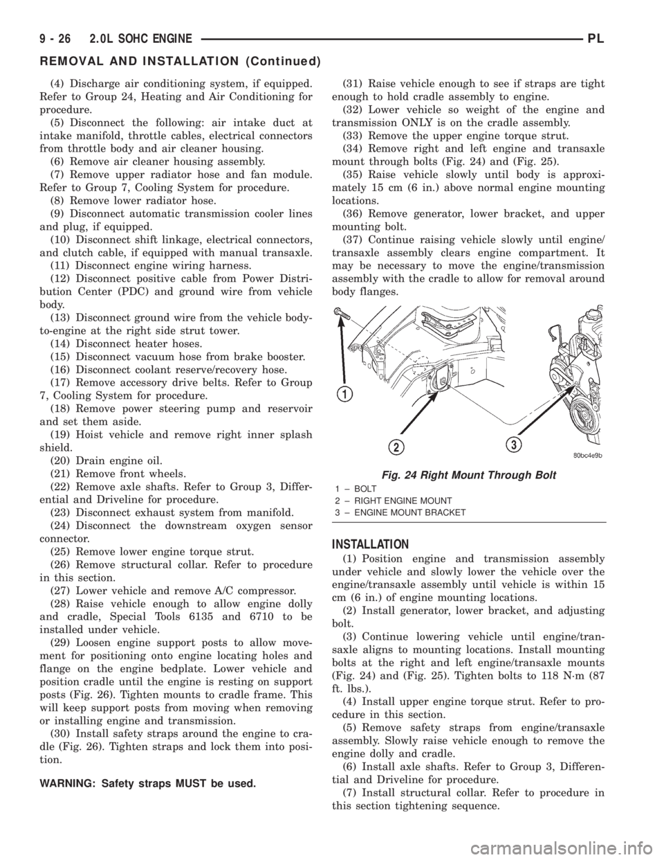
(29) Loosen engine support posts to allow move-
ment for positioning onto engine locating holes and
flange on the engine bedplate. Lower vehicle and
position cradle until the engine is resting on support
posts (Fig. 26). Tighten mounts to cradle frame. This
will keep support posts from moving when removing
or installing engine and transmission.
(30) Install safety straps around the engine to cra-
dle (Fig. 26). Tighten straps and lock them into posi-
tion.
WARNING: Safety straps MUST be used.(31) Raise vehicle enough to see if straps are tight
enough to hold cradle assembly to engine.
(32) Lower vehicle so weight of the engine and
transmission ONLY is on the cradle assembly.
(33) Remove the upper engine torque strut.
(34) Remove right and left engine and transaxle
mount through bolts (Fig. 24) and (Fig. 25).
(35) Raise vehicle slowly until body is approxi-
mately 15 cm (6 in.) above normal engine mounting
locations.
(36) Remove generator, lower bracket, and upper
mounting bolt.
(37) Continue raising vehicle slowly until engine/
transaxle assembly clears engine compartment. It
may be necessary to move the engine/transmission
assembly with the cradle to allow for removal around
body flanges.
INSTALLATION
(1) Position engine and transmission assembly
under vehicle and slowly lower the vehicle over the
engine/transaxle assembly until vehicle is within 15
cm (6 in.) of engine mounting locations.
(2) Install generator, lower bracket, and adjusting
bolt.
(3) Continue lowering vehicle until engine/tran-
saxle aligns to mounting locations. Install mounting
bolts at the right and left engine/transaxle mounts
(Fig. 24) and (Fig. 25). Tighten bolts to 118 N´m (87
ft. lbs.).
(4) Install upper engine torque strut. Refer to pro-
cedure in this section.
(5) Remove safety straps from engine/transaxle
assembly. Slowly raise vehicle enough to remove the
engine dolly and cradle.
(6) Install axle shafts. Refer to Group 3, Differen-
tial and Driveline for procedure.
(7) Install structural collar. Refer to procedure in
this section tightening sequence.
Fig. 24 Right Mount Through Bolt
1 ± BOLT
2 ± RIGHT ENGINE MOUNT
3 ± ENGINE MOUNT BRACKET
9 - 26 2.0L SOHC ENGINEPL
REMOVAL AND INSTALLATION (Continued)
Page 843 of 1285
DESCRIPTION AND OPERATION
INJECTION SYSTEM
All engines used in this section have a sequential
Multi-Port Electronic Fuel Injection system. The MPI
system is computer regulated and provides precise
air/fuel ratios for all driving conditions. The Power-
train Control Module (PCM) operates the fuel injec-
tion system.
The PCM regulates:
²Ignition timing
²Air/fuel ratio
²Emission control devices
²Cooling fan
²Charging system
²Idle speed
²Vehicle speed control
Various sensors provide the inputs necessary for
the PCM to correctly operate these systems. In addi-
tion to the sensors, various switches also provide
inputs to the PCM.
All inputs to the PCM are converted into signals.
The PCM can adapt its programming to meet chang-
ing operating conditions.
Fuel is injected into the intake port above the
intake valve in precise metered amounts through
electrically operated injectors. The PCM fires the
injectors in a specific sequence. Under most operat-
ing conditions, the PCM maintains an air fuel ratio
of 14.7 parts air to 1 part fuel by constantly adjust-
ing injector pulse width. Injector pulse width is the
length of time the injector is open.
The PCM adjusts injector pulse width by opening
and closing the ground path to the injector. Engine
RPM (speed) and manifold absolute pressure (air
density) are the primary inputs that determine injec-
tor pulse width.
MODES OF OPERATION
OPERATION
As input signals to the PCM change, the PCM
adjusts its response to output devices. For example,
the PCM must calculate a different injector pulse
width and ignition timing for idle than it does for
Wide Open Throttle (WOT). There are several differ-
ent modes of operation that determine how the PCM
responds to the various input signals.
There are two different areas of operation, OPEN
LOOP and CLOSED LOOP.
During OPEN LOOP modes the PCM receives
input signals and responds according to preset PCM
programming. Inputs from the upstream and down-
stream heated oxygen sensors are not monitored dur-
ing OPEN LOOP modes, except for heated oxygensensor diagnostics (they are checked for shorted con-
ditions at all times).
During CLOSED LOOP modes the PCM monitors
the inputs from the upstream and downstream
heated oxygen sensors. The upstream heated oxygen
sensor input tells the PCM if the calculated injector
pulse width resulted in the ideal air-fuel ratio of 14.7
to one. By monitoring the exhaust oxygen content
through the upstream heated oxygen sensor, the
PCM can fine tune injector pulse width. Fine tuning
injector pulse width allows the PCM to achieve opti-
mum fuel economy combined with low emissions.
For the PCM to enter CLOSED LOOP operation,
the following must occur:
(1) Engine coolant temperature must be over 35ÉF.
²If the coolant is over 35É the PCM will wait 44
seconds.
²If the coolant is over 50ÉF the PCM will wait 38
seconds.
²If the coolant is over 167ÉF the PCM will wait
11 seconds.
(2) For other temperatures the PCM will interpo-
late the correct waiting time.
(3) O2 sensor must read either greater than 0.745
volts or less than 0.1 volt.
(4) The multi-port fuel injection systems has the
following modes of operation:
²Ignition switch ON (Zero RPM)
²Engine start-up
²Engine warm-up
²Cruise
²Idle
²Acceleration
²Deceleration
²Wide Open Throttle
²Ignition switch OFF
(5) The engine start-up (crank), engine warm-up,
deceleration with fuel shutoff and wide open throttle
modes are OPEN LOOP modes. Under most operat-
ing conditions, the acceleration, deceleration (with
A/C on), idle and cruise modes,with the engine at
operating temperatureare CLOSED LOOP modes.
IGNITION SWITCH ON (ZERO RPM) MODE
When the ignition switch activates the fuel injec-
tion system, the following actions occur:
²The PCM monitors the engine coolant tempera-
ture sensor and throttle position sensor input. The
PCM determines basic fuel injector pulse width from
this input.
²The PCM determines atmospheric air pressure
from the MAP sensor input to modify injector pulse
width.
When the key is in the ON position and the engine
is not running (zero rpm), the Auto Shutdown (ASD)
and fuel pump relays de-energize after approximately
14 - 22 FUEL SYSTEMPL