Page 2790 of 4592
S05938
No.2 Timing Belt
Cover
No.1 Timing Belt
Cover
Crankshaft
Pulley
Crankshaft Position Sensor
Connector
Crankshaft Position Sensor Wire ClampWire
Clamp
N´m (kgf´cm, ft´lbf):Specified torqueGenerator * Gasket
Timing Belt Guide Generator Wire
Generator Connector
Wire ClampWire
Clamp
108 (1,100, 80)
* Gasket
* Replace only if damaged
± IGNITION (5S±FE)CRANKSHAFT POSITION SENSOR
IG±11
1693 Author�: Date�:
Page 2892 of 4592
B06345
No.2 Timing Belt Cover
No.1 Timing Belt Cover* Gasket
Wire
ClampGeneratorGenerator Wire
Generator Connector
Crankshaft Pulley
No.2 Idler Pulley
Oil Pump Pulley
Crankshaft
Timing Pulley
Crankshaft Position SensorTiming Belt Guide
Wire ClampWire
Clamp
Timing Belt
Clamp
No.1 Idler Pulley
Tension Spring � GasketClamp
� Gasket
� GasketHigh±Tension Cord
Spark Plug
Oil Strainer
Drain Plug
N´m (kgf´cm, ft´lbf): Specified torque
� Non±reusable partx 17
* Gasket
* Replace only if damagedOil Pump
x 10
8.8 (90, 78 in.´lbf)5.4 (55, 48 in.´lbf)
5.4 (55, 48 in.´lbf)
24 (245, 18)
42 (425, 31)
108 (1,100, 80)
18 (180, 13)
42 (425, 31)
Oil Pan
± LUBRICATION (5S±FE)OIL PUMP
LU±5
1651 Author�: Date�:
Page 2894 of 4592
OIL PUMP
LU±7
1653 Author�: Date�:
REMOVAL
HINT:
When repairing the oil pump, the oil pan and strainer should be
removed and cleaned.
1.")
LU03K±03
S05311
S05952
SST
SST
S05928
± LUBRICATION (5S±FE)OIL PUMP
LU±7
1653 Author�: Date�:
REMOVAL
HINT:
When repairing the oil pump, the oil pan and strainer should be
removed and cleaned.
1. DRAIN ENGINE OIL
2. REMOVE FRONT EXHAUST PIPE (See page EM±69)
3. REMOVE NO.2 EXHAUST MANIFOLD STAY AND LH
STIFFENER PLATE (See page EM±69)
4. REMOVE EXHAUST PIPE BRACKET, OIL PAN INSU-
LATOR AND NO.2 REAR END PLATE
(See page EM±69)
5. REMOVE OIL PAN
(a) Remove the oil dipstick.
(b) Remove the 17 bolts and 2 nuts.
(c) Insert the blade of SST between the cylinder block and oil
pan, and cut off applied sealer and remove the oil pan.
SST 09032±00100
NOTICE:
�Do not use SST for the oil pump body side and rear oil
seal retainer.
�Be careful not to damage the oil pan flange.
6. REMOVE OIL STRAINER
Remove the bolt, 2 nuts, oil strainer and gasket.
7. REMOVE TIMING BELT (See page EM±17)
8. REMOVE NO.2 IDLER PULLEY
Remove the bolt and idler pulley.
9. REMOVE CRANKSHAFT TIMING PULLEY
(See page EM±17)
10. REMOVE OIL PUMP PULLEY (See page EM±17)
Page 2900 of 4592

± LUBRICATION (5S±FE)OIL PUMP
LU±13
1659 Author�: Date�:
INSTALLATION
1. INSTALL OIL PUMP
Install")
LU03P±03
Z19249
A
BB AA A AA A
A A
A
S05928
LU0420
Seal Width
3 ± 5 mm
A
A
BBC
C
5 mm (0.20 in.)
± LUBRICATION (5S±FE)OIL PUMP
LU±13
1659 Author�: Date�:
INSTALLATION
1. INSTALL OIL PUMP
Install a new gasket and the oil pump with the 12 bolts. Uniformi-
ty tighten the bolts in several passes.
Torque: 8.8 N´m (90 kgf´cm, 78 in.´lbf)
HINT:
Each bolt length is indicated in the illustration.
Bolt length:
25 mm (0.98 in.) for A
35 mm (1.38 in.) for B
2. INSTALL OIL PUMP PULLEY (See page EM±23)
3. INSTALL CRANKSHAFT TIMING PULLEY
(See page EM±23)
4. INSTALL NO.2 IDLER PULLEY (See page EM±23)
5. INSTALL TIMING BELT (See page EM±23)
6. INSTALL OIL STRAINER
Install a new gasket and the oil strainer with the bolt and 2 nuts.
Torque: 5.4 N´m (55 kgf´cm, 48 in.´lbf)
7. INSTALL OIL PAN
(a) Remove any old seal packing (FIPG) material and be
careful not to drop any oil on the contact surfaces of the
oil pan and cylinder block.
�Using a razor blade and gasket scraper, remove all
the old packing (FIPG) material from the gasket sur-
faces and sealing groove.
�Thoroughly clean all components to remove all the
loose material.
�Using a non±residue solvent, clean both sealing
surface.
NOTICE:
Do not use a solvent which will affect the painted surfaces.
(b) Apply seal packing to the oil pan shown in the illustration.
Seal packing: Part No. 08826±00080 or equivalent
�Install a nozzle that has been cut to a 3 ± 5 mm (0.12
± 0.20 in.) opening.
�Parts must be assembled within 5 minutes of ap-
plication. Otherwise the material must be removed
and reapplied.
Page 2911 of 4592
B06384
No.2 Timing Belt CoverTiming Belt
Gasket
Timing Belt Guide
No.2 Generator
Bracket RH Engine Mounting Bracket
Crankshaft
PulleyGasket
Engine Wire
Protector
RH Camshaft Timing Pulley
No.2 Idler Pulley
Crankshaft
Timing PulleyDust Boot
Timing Belt Plate Plate Washer
�
Timing Belt Tensioner
N´m (kgf´cm, ft´lbf) : Specified torque
� Non±reusable part No.1 Timing Belt Cover
LH Camshaft
Timing Pulley
No.1 Idler Pulley
� Precoated part
* For use with SST
28 (290, 21)
215 (2,200, 159)
125 (1,300, 94)*88 (900, 65)43 (440, 32)
34 (350, 25)
27 (280, 20)
125 (1,300, 94)
LU±6
± LUBRICATION (1MZ±FE)OIL PUMP
1670 Author�: Date�:
Page 2912 of 4592
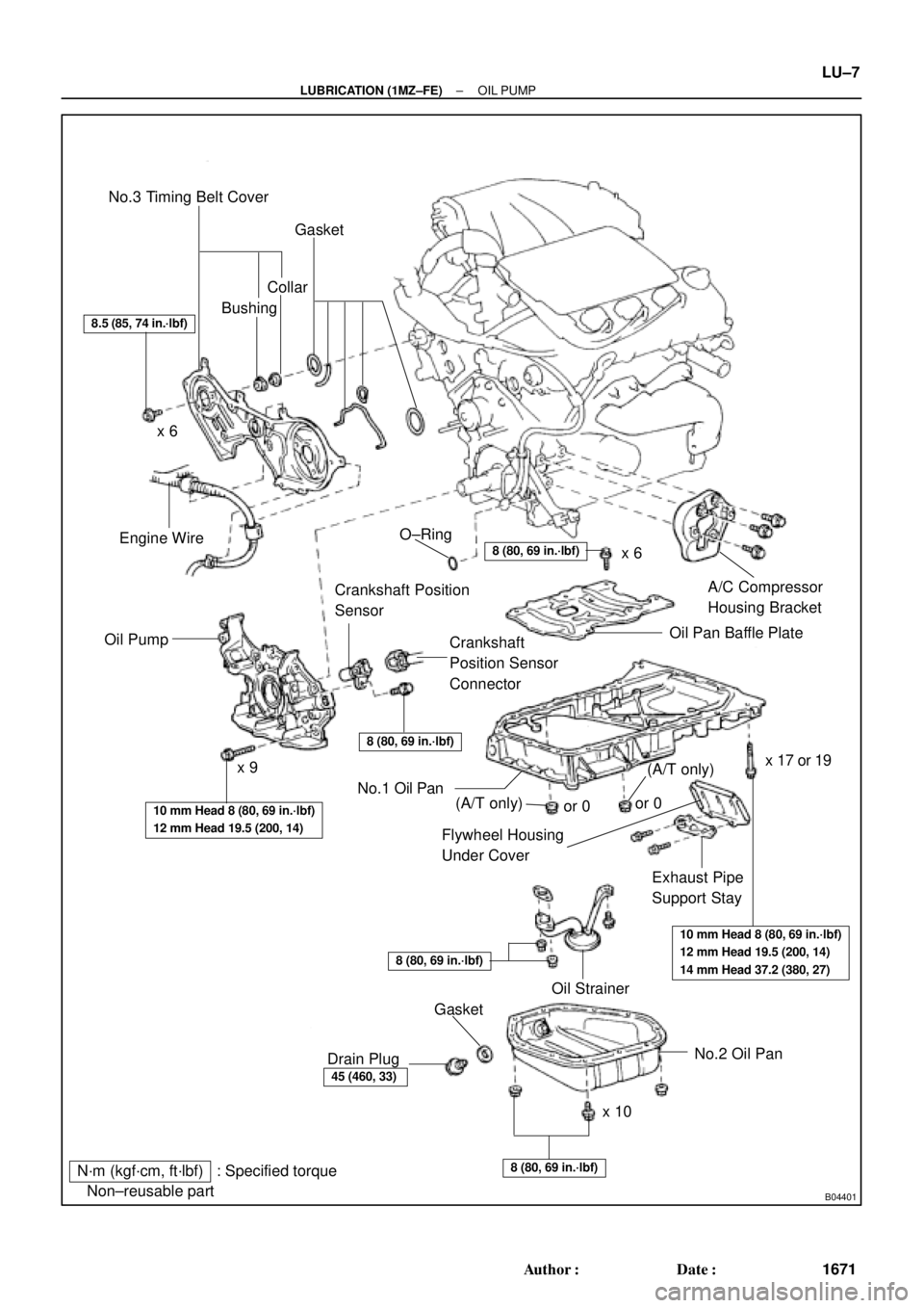
B04401
N´m (kgf´cm, ft´lbf) : Specified torque
� Non±reusable partNo.3 Timing Belt Cover
Gasket
BushingCollar
A/C Compressor
Housing Bracket
Oil Pan Baffle Plate
Crankshaft
Position Sensor
Connector Crankshaft Position
Sensor
Oil PumpEngine Wire
Flywheel Housing
Under Cover
Exhaust Pipe
Support Stay
Oil Strainer
No.2 Oil Pan
x 10x 6
x 9� O±Ring
No.1 Oil Pan
� Gasket
Drain Plug
8.5 (85, 74 in.´lbf)
8 (80, 69 in.´lbf)
8 (80, 69 in.´lbf)
10 mm Head 8 (80, 69 in.´lbf)
12 mm Head 19.5 (200, 14)
10 mm Head 8 (80, 69 in.´lbf)
12 mm Head 19.5 (200, 14)
14 mm Head 37.2 (380, 27)
8 (80, 69 in.´lbf)
45 (460, 33)
8 (80, 69 in.´lbf)
x 6
x 17 or 19
(A/T only)(A/T only)or 0or 0
± LUBRICATION (1MZ±FE)OIL PUMP
LU±7
1671 Author�: Date�:
Page 2914 of 4592
LU028±03
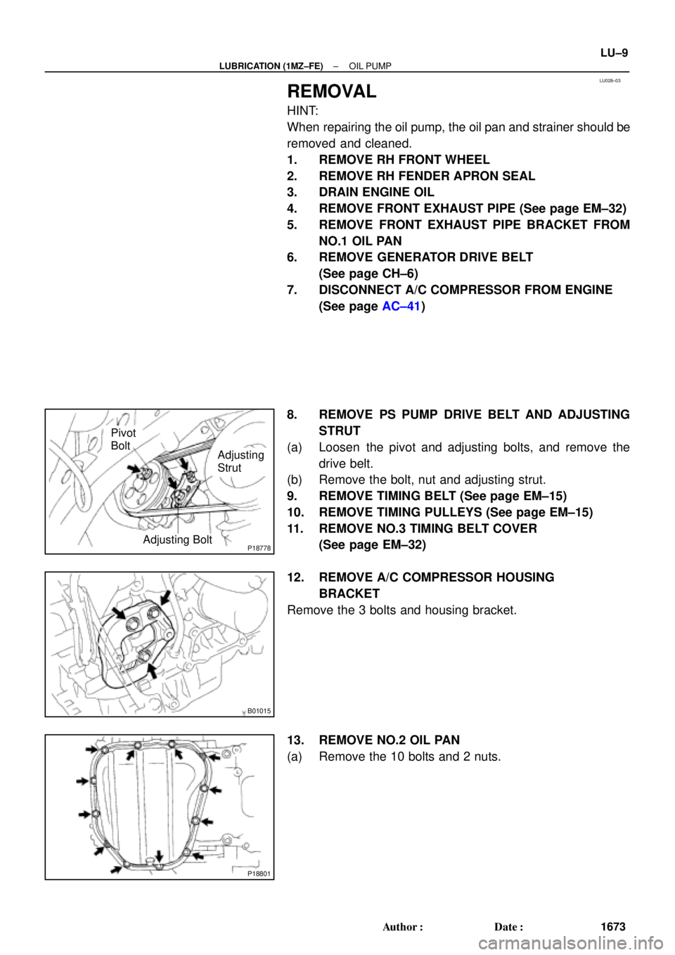
P18778Adjusting Bolt
Adjusting
Strut Pivot
Bolt
B01015
P18801
± LUBRICATION (1MZ±FE)OIL PUMP
LU±9
1673 Author�: Date�:
REMOVAL
HINT:
When repairing the oil pump, the oil pan and strainer should be
removed and cleaned.
1. REMOVE RH FRONT WHEEL
2. REMOVE RH FENDER APRON SEAL
3. DRAIN ENGINE OIL
4. REMOVE FRONT EXHAUST PIPE (See page EM±32)
5. REMOVE FRONT EXHAUST PIPE BRACKET FROM
NO.1 OIL PAN
6. REMOVE GENERATOR DRIVE BELT
(See page CH±6)
7. DISCONNECT A/C COMPRESSOR FROM ENGINE
(See page AC±41)
8. REMOVE PS PUMP DRIVE BELT AND ADJUSTING
STRUT
(a) Loosen the pivot and adjusting bolts, and remove the
drive belt.
(b) Remove the bolt, nut and adjusting strut.
9. REMOVE TIMING BELT (See page EM±15)
10. REMOVE TIMING PULLEYS (See page EM±15)
11. REMOVE NO.3 TIMING BELT COVER
(See page EM±32)
12. REMOVE A/C COMPRESSOR HOUSING
BRACKET
Remove the 3 bolts and housing bracket.
13. REMOVE NO.2 OIL PAN
(a) Remove the 10 bolts and 2 nuts.
Page 2923 of 4592
OIL PUMP
1682 Author�: Date�:
(b) Apply seal packing to the No.2 oil pan as shown in the il-
lustration.
Seal packing:
Part No. 08826�")
P12568
A
A
BB
Seal Width
4 ± 5 mm LU±18
± LUBRICATION (1MZ±FE)OIL PUMP
1682 Author�: Date�:
(b) Apply seal packing to the No.2 oil pan as shown in the il-
lustration.
Seal packing:
Part No. 08826±00080 or equivalent
�Install a nozzle that has been cut to a 4 ± 5 mm (0.16
± 0.20 in.) opening.
HINT:
Avoid applying an excessive amount to the surface.
�Parts must be assembled within 3 minutes of ap-
plication. Otherwise the material must be removed
and reapplied.
�Immediately remove nozzle from the tube and rein-
stall cap.
(c) Install the No.2 oil pan with the 10 bolts and 2 nuts. Uni-
formly tighten the bolts and nuts in several passes.
Torque: 8 N´m (80 kgf´cm, 69 in.´lbf)
7. INSTALL A/C COMPRESSOR HOUSING BRACKET
Torque: 25 N´m (250 kgf´cm, 18 ft´lbf)
8. INSTALL NO.3 TIMING BELT COVER
(See page EM±21)
9. INSTALL TIMING PULLEYS (See page EM±21)
10. INSTALL TIMING BELT (See page EM±21)
11. INSTALL ADJUSTING STRUT AND PS PUMP DRIVE
BELT
(a) Temporarily install the adjusting strut with the bolt and the
nut.
(b) Install the drive belt with the pivot and adjusting bolts.
Torque: 43.1 N´m (440 kgf´cm, 32 ft´lbf)
(c) Tighten the nut.
Torque: 43.1 N´m (440 kgf´cm, 32 ft´lbf)
12. INSTALL A/C COMPRESSOR (See page AC±47)
13. INSTALL GENERATOR DRIVE BELT
(See page CH±16)
14. INSTALL FRONT EXHAUST PIPE BRACKET TO
NO.1 OIL PAN
Torque: 21 N´m (210 kgf´cm, 15 ft´lbf)
15. INSTALL FRONT EXHAUST PIPE (See page EM±76)
16. REMOVE RH FENDER APRON SEAL
17. REMOVE RH FRONT WHEEL
18. FILL ENGINE WITH OIL
19. START ENGINE AND CHECK FOR LEAKS
20. RECHECK ENGINE OIL LEVEL
:Specified torqueGene")