Page 2694 of 4592
A05070
Timing Belt
Gasket No.2 Timing Belt Cover
RH Engine Mounting Bracket
Crankshaft
Pulley No.1 Timing Belt Cover
Gasket
Engine Wire
Protector
No.2 Idler Pulley
RH Camshaft Timing Pulley
LH Camshaft
Timing Pulley
Timing Belt TensionerTiming Belt Guide
No.2 Generator
Bracket
Dust Boot
N´m (kgf´cm, ft´lbf) : Specified torque
* For use with SST� Non±reusable part
28 (290, 21)
215 (2,200, 159)
125 (1,300, 94)
*88 (900, 65)
27 (280, 20)
43 (440, 32)
125 (1,300, 94)
± ENGINE MECHANICAL (1MZ±FE)CYLINDER HEAD
EM±29
1315 Author�: Date�:
Page 2695 of 4592
Engine Wire
 ProtectorEngine Wire
Protector
Heated Oxygen Sensor
(Bank 1 Sensor 1)
Connector
RH Exhaust Manifold
(Except")
A06635� Non±reusable part: Specified torque
N´m (kgf´cm, ft´lbf)Engine Wire
Engine Wire ProtectorEngine Wire
Protector
Heated Oxygen Sensor
(Bank 1 Sensor 1)
Connector
RH Exhaust Manifold
(Except M/T and California A/T)
34 (350,25)
x 6
12 (120, 9)
PS Pump Bracket
43 (440, 32)
No.1 EGR Pipe � Gasket
Cylinder Head Rear Plate
Ground Strap
Water Inlet
Pipe � O±Ring
Gasket
20 (200, 14)
CollarBushing No.3 Timing
Belt Cover
x 6
x 6
� O±Ring
49 (500, 36)LH Exhaust
Manifold Stay
(Except M/T and
California A/T ) Oil Dipstick Guide Engine WireRH Exhaust Manifold
RH Exhaust
Manifold Stay
� Gasket
20 (200, 14)
Heated Oxygen Sensor
(Bank 2 Sensor 1)
Connector
34 (350,25)
49 (500, 36)
LH Exhaust
Manifold Stay
LH Exhaust Manifold
California A/T
M/T and California A/T
� Gasket
Camshaft
Position Sensor
ConnectorGasket RH
Exhaust
Manifold
Stay
(Except M/T and Calif. A/T)
Camshaft Position Sensor
LH Exhaust Manifold
(Except California A/T)
49 (500, 36)
x 6 EM±30
± ENGINE MECHANICAL (1MZ±FE)CYLINDER HEAD
1316 Author�: Date�:
Page 2699 of 4592
CYLINDER HEAD
1320 Author�: Date�:
10. REMOVE WATER OUTLET
(a) Disconnect the ECT sender gauge connector.
(b) Disconne")
P20049Gasket
A05077
Clamp
Clamp
Clamp
S04786
EM±34
± ENGINE MECHANICAL (1MZ±FE)CYLINDER HEAD
1320 Author�: Date�:
10. REMOVE WATER OUTLET
(a) Disconnect the ECT sender gauge connector.
(b) Disconnect the ECT sensor connector.
(c) Disconnect the ground strap (connector).
(d) Disconnect the radiator hose.
(e) Disconnect the engine coolant reservoir hose.
(f) Remove the 2 bolts, 2 nuts and 2 plate washers.
(g) Disconnect the water bypass hose, and remove the water
outlet.
(h) Remove the 2 gaskets.
11. REMOVE GENERATOR DRIVE BELT
(See page CH±6)
12. REMOVE PS PUMP (See page SR±21)
13. REMOVE IGNITION COILS
14. REMOVE SPARK PLUGS
15. REMOVE TIMING BELT (See page EM±15)
16. REMOVE CAMSHAFT TIMING PULLEYS
(See page EM±15)
17. REMOVE NO.2 IDLER PULLEY (See page EM±15)
18. REMOVE NO.3 TIMING BELT COVER
(a) Disconnect the 3 engine wire clamps from the timing belt
cover.
(b) Remove the 6 bolts and timing belt cover.
19. DISCONNECT ENGINE WIRE PROTECTOR FROM
REAR SIDE
Remove the 2 nuts, and disconnect the engine wire protector
from the RH cylinder head and water inlet.
Page 2730 of 4592
Except California A/T
S04789
Ground
Strap
Inlet PipeRear
Plate
± ENGINE MECHANICAL (1MZ±FE)CYLINDER HEAD
EM±65
1351")
P12710
New O±Ring
A01522
Manifold
Stay California A/T
Manifold Stay
(Except M/T)Except California A/T
S04789
Ground
Strap
Inlet PipeRear
Plate
± ENGINE MECHANICAL (1MZ±FE)CYLINDER HEAD
EM±65
1351 Author�: Date�:
13. INSTALL OIL DIPSTICK AND GUIDE
(a) Install a new O±ring to the dipstick guide.
(b) Apply soapy water to the O±ring.
(c) Push in the dipstick guide end into the guide hole of the
No.1 oil pan.
(d) Install the dipstick guide with the bolt.
Torque: 8 N´m (80 kgf´cm, 69 in.´lbf)
(e) Install the dipstick.
14. INSTALL CAMSHAFT POSITION SENSOR
15. INSTALL LH EXHAUST MANIFOLD
(a) Install a new gasket and the exhaust manifold with the 6
nuts. Uniformly tighten the nuts in several passes.
Torque: 49 N´m (500 kgf´cm, 36 ft´lbf)
(b) Except M/T:
Install the exhaust manifold stay with the bolt and nut. Al-
ternately tighten the bolt and nut.
Torque:
California A/T:
34 N´m (350 kgf´cm, 25 ft´lbf)
Except California A/T:
20 N´m (200 kgf´cm, 15 ft´lbf)
(c) California:
Connect the A/F sensor connector.
(d) Except California:
Connect the heated oxygen sensor (bank 2 sensor 1)
connector.
16. INSTALL WATER INLET PIPE
(a) Install a new O±ring to the water inlet pipe.
(b) Apply soapy water to the O±ring.
(c) Connect the water inlet pipe to the water inlet.
(d) Install the bolt holding the water inlet pipe to the cylinder
head.
Torque: 19.5 N´m (200 kgf´cm, 14 ft´lbf)
17. INSTALL CYLINDER HEAD REAR PLATE
Torque: 8 N´m (80 kgf´cm, 69 in.´lbf)
18. INSTALL ENGINE WIRE PROTECTOR
19. INSTALL NO.3 TIMING BELT COVER
(a) Check that the timing belt cover gaskets have no cracks
or peeling, etc.
If the gaskets have cracks or peeling etc., replace them using
these steps:
�Using a screwdriver and gasket scraper, remove all
the old gasket material.
�Thoroughly clean all components to remove all the
loose material.
Page 2731 of 4592

L = 180 mm (7.09 in.)L = 72 mm (2.83 in.)
L = 335 mm (13.19 in.)L = 180 mm
(7.09 in.)
L = Length Join
LineJoin
Line
Z14262New Gasket
A01808
8
6
5
4
3
2
1
9
10
7
11
EM")
A05194
L = 133 mm (5.24 in.)
L = 180 mm (7.09 in.)L = 72 mm (2.83 in.)
L = 335 mm (13.19 in.)L = 180 mm
(7.09 in.)
L = Length Join
LineJoin
Line
Z14262New Gasket
A01808
8
6
5
4
3
2
1
9
10
7
11
EM±66
± ENGINE MECHANICAL (1MZ±FE)CYLINDER HEAD
1352 Author�: Date�: �
Remove the backing paper from a new gasket and
install the gasket evenly to the part of the timing belt
cover shaded black in the illustration.
NOTICE:
When joining 2 gaskets, do not leave a gap between them.
Cut off any excess gasket.
�After installing the gasket, press down on it so that
the adhesive firmly sticks to the timing belt cover.
(b) Install the timing belt cover with the 6 bolts.
Torque: 8.5 N´m (85 kgf´cm, 74 in.´lbf)
(c) Install the 3 engine wire clamps to the timing belt cover.
20. INSTALL NO.2 IDLER PULLEY (See page EM±21)
21. INSTALL CAMSHAFT TIMING PULLEYS
(See page EM±21)
22. INSTALL TIMING BELT (See page EM±21)
23. INSTALL SPARK PLUGS
24. INSTALL IGNITION COILS
25. INSTALL PS PUMP DRIVE BELT
26. INSTALL GENERATOR DRIVE BELT
(See page SR±28)
27. INSTALL WATER OUTLET
(a) Install 2 new gaskets.
(b) Connect the water outlet to the bypass hose.
(c) Install the water outlet with the 2 bolts, 2 nuts and 2 plate
washers. Alternately tighten the bolts and nuts.
Torque: 15 N´m (150 kgf´cm, 11 ft´lbf)
NOTICE:
Do not scratch the seal surface of the water outlet with the
stud bolt.
(d) Connect the ECT sender gauge connector.
(e) Connect the ECT sensor connector.
(f) Connect the ground strap (connector).
(g) Connect the radiator hose.
(h) Connect the engine coolant reservoir hose.
28. INSTALL INTAKE MANIFOLD ASSEMBLY
(a) Install the intake manifold, delivery pipe and injectors as-
sembly with the 9 bolts, 2 plate washers and 2 nuts. Uni-
formly tighten the bolts and nuts, in several passes, in the
sequence shown.
Torque: 15 N´m (150 kgf´cm, 11 ft´lbf)
Page 2748 of 4592
EM051±04
S04921
P12946
P18761
P12389
SST
± ENGINE MECHANICAL (1MZ±FE)CYLINDER BLOCK
EM±83
1369 Author�: Date�:
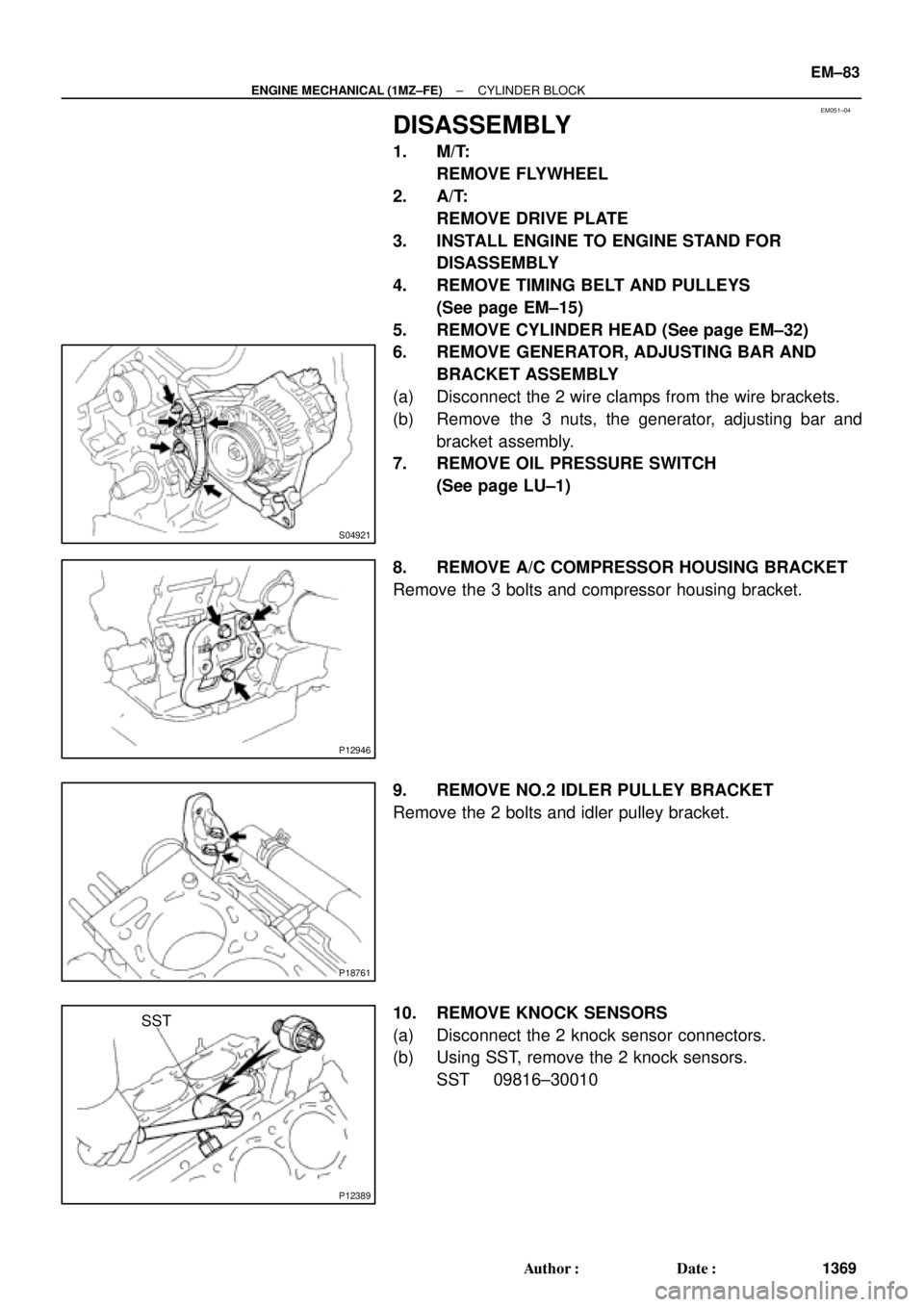
DISASSEMBLY
1. M/T:
REMOVE FLYWHEEL
2. A/T:
REMOVE DRIVE PLATE
3. INSTALL ENGINE TO ENGINE STAND FOR
DISASSEMBLY
4. REMOVE TIMING BELT AND PULLEYS
(See page EM±15)
5. REMOVE CYLINDER HEAD (See page EM±32)
6. REMOVE GENERATOR, ADJUSTING BAR AND
BRACKET ASSEMBLY
(a) Disconnect the 2 wire clamps from the wire brackets.
(b) Remove the 3 nuts, the generator, adjusting bar and
bracket assembly.
7. REMOVE OIL PRESSURE SWITCH
(See page LU±1)
8. REMOVE A/C COMPRESSOR HOUSING BRACKET
Remove the 3 bolts and compressor housing bracket.
9. REMOVE NO.2 IDLER PULLEY BRACKET
Remove the 2 bolts and idler pulley bracket.
10. REMOVE KNOCK SENSORS
(a) Disconnect the 2 knock sensor connectors.
(b) Using SST, remove the 2 knock sensors.
SST 09816±30010
Page 2775 of 4592
P00601
Adhesive
A05416
1
2 34 5
67
8
EM±110
± ENGINE MECHANICAL (1MZ±FE)CYLINDER BLOCK
1396 Author�: Date�:
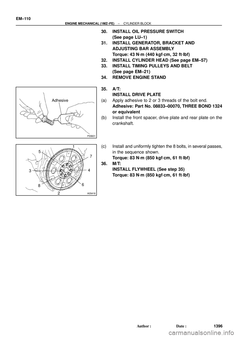
30. INSTALL OIL PRESSURE SWITCH
(See page LU±1)
31. INSTALL GENERATOR, BRACKET AND
ADJUSTING BAR ASSEMBLY
Torque: 43 N´m (440 kgf´cm, 32 ft´lbf)
32. INSTALL CYLINDER HEAD (See page EM±57)
33. INSTALL TIMING PULLEYS AND BELT
(See page EM±21)
34. REMOVE ENGINE STAND
35. A/T:
INSTALL DRIVE PLATE
(a) Apply adhesive to 2 or 3 threads of the bolt end.
Adhesive: Part No. 08833±00070, THREE BOND 1324
or equivalent
(b) Install the front spacer, drive plate and rear plate on the
crankshaft.
(c) Install and uniformly tighten the 8 bolts, in several passes,
in the sequence shown.
Torque: 83 N´m (850 kgf´cm, 61 ft´lbf)
36. M/T:
INSTALL FLYWHEEL (See step 35)
Torque: 83 N´m (850 kgf´cm, 61 ft´lbf)
Page 2788 of 4592
S05938
No.2 Timing Belt
Cover
No.1 Timing Belt
Cover
Crankshaft
Pulley
Crankshaft Position Sensor
Connector
Crankshaft Position Sensor Wire ClampWire
Clamp
N´m (kgf´cm, ft´lbf):Specified torqueGenerator * Gasket
Timing Belt Guide Generator Wire
Generator Connector
Wire ClampWire
Clamp
108 (1,100, 80)
* Gasket
* Replace only if damaged
± IGNITION (5S±FE)CRANKSHAFT POSITION SENSOR
IG±11
1693 Author�: Date�:

:Specified torqueGene")