Page 2664 of 4592
± ENGINE MECHANICAL (5S±FE)CYLINDER BLOCK
EM±113
1285 Author�: Date�:
(f) Install the wire clamp to the generator drive belt adjusting
bar.
(g) Connect the IAC valve water bypass hose to the water by-
pass pipe.
(h) Connect the water bypass hose (from the water bypass
pipe) to the water outlet.
(i) Install the camshafts. (See page EM±53)
(j) Install the cylinder head cover.
(1) Install the cylinder head cover. (See page EM±53)
(2) Connect the PCV hose to the intake manifold.
(k) Install the No.3 timing belt cover with the 3 bolts.
Torque: 7.8 N´m (80 kgf´cm, 69 in.´lbf)
23. INSTALL TIMING BELT AND PULLEYS
(See page EM±23)
24. DISCONNECT ENGINE FROM ENGINE STAND
Page 2669 of 4592
VALVE CLEARANCE
1290 Author�: Date�:
VALVE CLEARANCE
INSPECTION
HINT:
Inspect and adjust the val")
EM04K±04
P18805
P13074
RH EX
RH IN
LH IN
LH EX 13
6
23
1
6
2Front EM±4
± ENGINE MECHANICAL (1MZ±FE)VALVE CLEARANCE
1290 Author�: Date�:
VALVE CLEARANCE
INSPECTION
HINT:
Inspect and adjust the valve clearance when the engine is cold.
1. REMOVE RH FENDER APRON SEAL
2. DRAIN ENGINE COOLANT
3. REMOVE V±BANK COVER
(a) Using a 5 mm hexagon wrench, remove the 2 nuts.
(b) Disconnect the 2 clips, and remove the cover.
4. REMOVE HIGH±TENSION CODE SET
(See page IG±7)
5. REMOVE AIR INTAKE CHAMBER ASSEMBLY
(See page EM±32)
6. REMOVE IGNITION COILS
7. DISCONNECT RADIATOR HOSE FROM WATER
OUTLET
8. REMOVE CYLINDER HEAD COVERS
(See page EM±32)
9. SET NO.1 CYLINDER TO TDC/COMPRESSION
(a) Turn the crankshaft pulley, and align its groove with the
timing mark º0º of the No.1 timing belt cover.
(b) Check that the valve lifters on the No.1 (IN and EX) are
loose.
If not, turn the crankshaft 1 revolution (360°) and align the mark
as above.
10. INSPECT VALVE CLEARANCE
(a) Check only those valves indicated in the illustration.
(1) Using a feeler gauge, measure the clearance be-
tween the valve lifter and camshaft.
(2) Record out of specification valve clearance mea-
surements. They will be used later to determine the
required replacement adjusting shim.
Valve clearance (Cold):
Intake0.15 ± 0.25 mm (0.006 ± 0.010 in.)
Exhaust0.25 ± 0.35 mm (0.010 ± 0.014 in.)
Page 2678 of 4592
EM04N±03
A06654
RH Fender Apron Seal
Generator Drive Belt Engine Moving
Control Rod
RH Engine Mounting Stay
No.2 RH Engine
Mounting Bracket
Ground Strap PS Pump Drive Belt
Engine Coolant Reservoir Hose
: Specified torqueNo.2 RH Engine
Mounting Stay (M/T)
64 (650, 47)
32 (320, 23)
64 (650, 47)
N´m (kgf´cm, ft´lbf)
± ENGINE MECHANICAL (1MZ±FE)TIMING BELT
EM±13
1299 Author�: Date�:
TIMING BELT
COMPONENTS
Page 2679 of 4592
B06384
No.2 Timing Belt CoverTiming Belt
Gasket
Timing Belt Guide
No.2 Generator
Bracket RH Engine Mounting Bracket
Crankshaft
PulleyGasket
Engine Wire
Protector
RH Camshaft Timing Pulley
No.2 Idler Pulley
Crankshaft
Timing PulleyDust Boot
Timing Belt Plate Plate Washer
�
Timing Belt Tensioner
N´m (kgf´cm, ft´lbf)
: Specified torque
� Non±reusable part No.1 Timing Belt Cover
LH Camshaft
Timing Pulley
No.1 Idler Pulley
� Precoated part
* For use with SST
28 (290, 21)
215 (2,200, 159)
125 (1,300, 94)*88 (900, 65)43 (440, 32)
34 (350, 25)
27 (280, 20)
125 (1,300, 94)
EM±14
± ENGINE MECHANICAL (1MZ±FE)TIMING BELT
1300 Author�: Date�:
Page 2680 of 4592
EM04O±04
P18754
P18816
P18817
SST
P18819
SST
± ENGINE MECHANICAL (1MZ±FE)TIMING BELT
EM±15
1301 Author�: Date�:
REMOVAL
1. REMOVE RH FRONT WHEEL
2. REMOVE RH FENDER APRON SEAL
3. REMOVE GENERATOR DRIVE BELT
(See page CH±6)
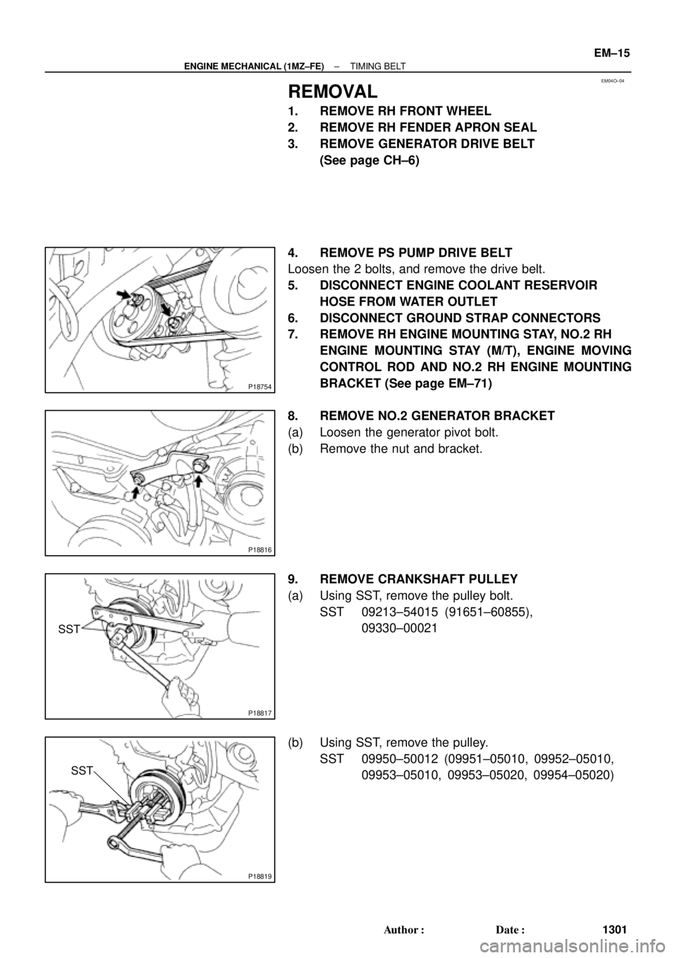
4. REMOVE PS PUMP DRIVE BELT
Loosen the 2 bolts, and remove the drive belt.
5. DISCONNECT ENGINE COOLANT RESERVOIR
HOSE FROM WATER OUTLET
6. DISCONNECT GROUND STRAP CONNECTORS
7. REMOVE RH ENGINE MOUNTING STAY, NO.2 RH
ENGINE MOUNTING STAY (M/T), ENGINE MOVING
CONTROL ROD AND NO.2 RH ENGINE MOUNTING
BRACKET (See page EM±71)
8. REMOVE NO.2 GENERATOR BRACKET
(a) Loosen the generator pivot bolt.
(b) Remove the nut and bracket.
9. REMOVE CRANKSHAFT PULLEY
(a) Using SST, remove the pulley bolt.
SST 09213±54015 (91651±60855),
09330±00021
(b) Using SST, remove the pulley.
SST 09950±50012 (09951±05010, 09952±05010,
09953±05010, 09953±05020, 09954±05020)
Page 2681 of 4592
P18820
A01800
Clamp
Clamp
P18814
P18808
A05052
EM±16
± ENGINE MECHANICAL (1MZ±FE)TIMING BELT
1302 Author�: Date�:
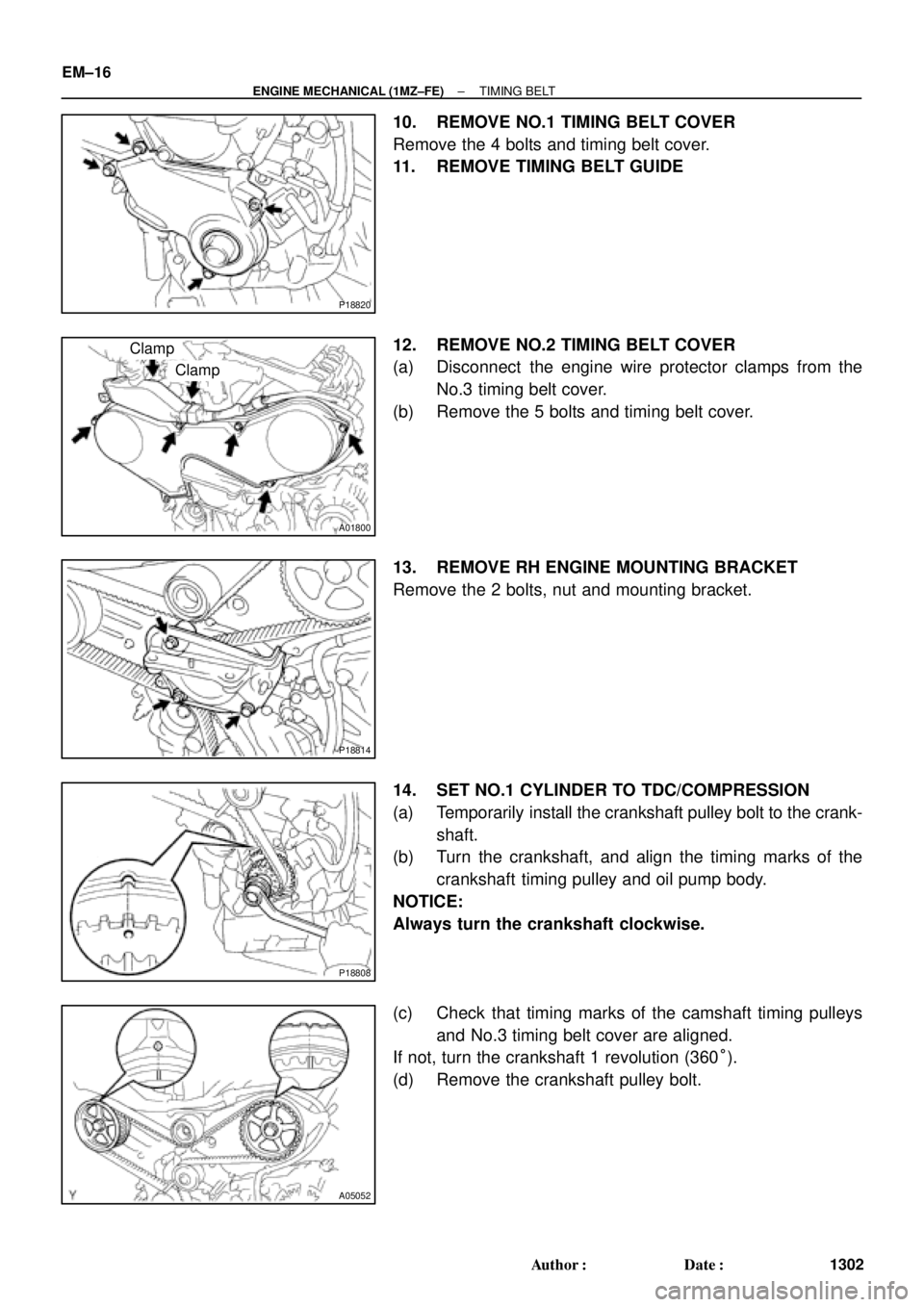
10. REMOVE NO.1 TIMING BELT COVER
Remove the 4 bolts and timing belt cover.
11. REMOVE TIMING BELT GUIDE
12. REMOVE NO.2 TIMING BELT COVER
(a) Disconnect the engine wire protector clamps from the
No.3 timing belt cover.
(b) Remove the 5 bolts and timing belt cover.
13. REMOVE RH ENGINE MOUNTING BRACKET
Remove the 2 bolts, nut and mounting bracket.
14. SET NO.1 CYLINDER TO TDC/COMPRESSION
(a) Temporarily install the crankshaft pulley bolt to the crank-
shaft.
(b) Turn the crankshaft, and align the timing marks of the
crankshaft timing pulley and oil pump body.
NOTICE:
Always turn the crankshaft clockwise.
(c) Check that timing marks of the camshaft timing pulleys
and No.3 timing belt cover are aligned.
If not, turn the crankshaft 1 revolution (360°).
(d) Remove the crankshaft pulley bolt.
Page 2682 of 4592
TIMING BELT
EM±17
1303 Author�: Date�:
15. IF REUSING TIMING BELT, CHECK INSTALLATION
MARKS ON TIMING BELT
Check that th")
A01804
A05053
P12764
SST RH
P12762
SST LH
A05055
± ENGINE MECHANICAL (1MZ±FE)TIMING BELT
EM±17
1303 Author�: Date�:
15. IF REUSING TIMING BELT, CHECK INSTALLATION
MARKS ON TIMING BELT
Check that there are 3 installation marks and front mark on the
timing belt.
If the installation and front marks have disappeared, before re-
moving the timing belt, place 3 new installation marks on the
timing belt to match the timing marks of the timing pulleys, and
place a new front mark on the timing belt.
16. REMOVE TIMING BELT TENSIONER
Alternately loosen the 2 bolts, and remove them, the tensioner
and dust boot.
17. REMOVE TIMING BELT
18. REMOVE CAMSHAFT TIMING PULLEYS
(a) Using SST, remove the bolt and RH timing pulley.
SST 09249±63010, 09960±10010 (09962±01000,
09963±01000)
(b) Using SST, remove the LH timing pulley.
SST 09960±10010 (09962±01000, 09963±01000)
HINT:
Arrange the camshaft timing pulleys (RH and LH sides).
19. REMOVE NO.2 IDLER PULLEY
Remove the bolt and idler pulley.
Page 2683 of 4592
A01802
10 mm
Hexagon
Wrench
Plate Washer
P20026
SST EM±18
± ENGINE MECHANICAL (1MZ±FE)TIMING BELT
1304 Author�: Date�:
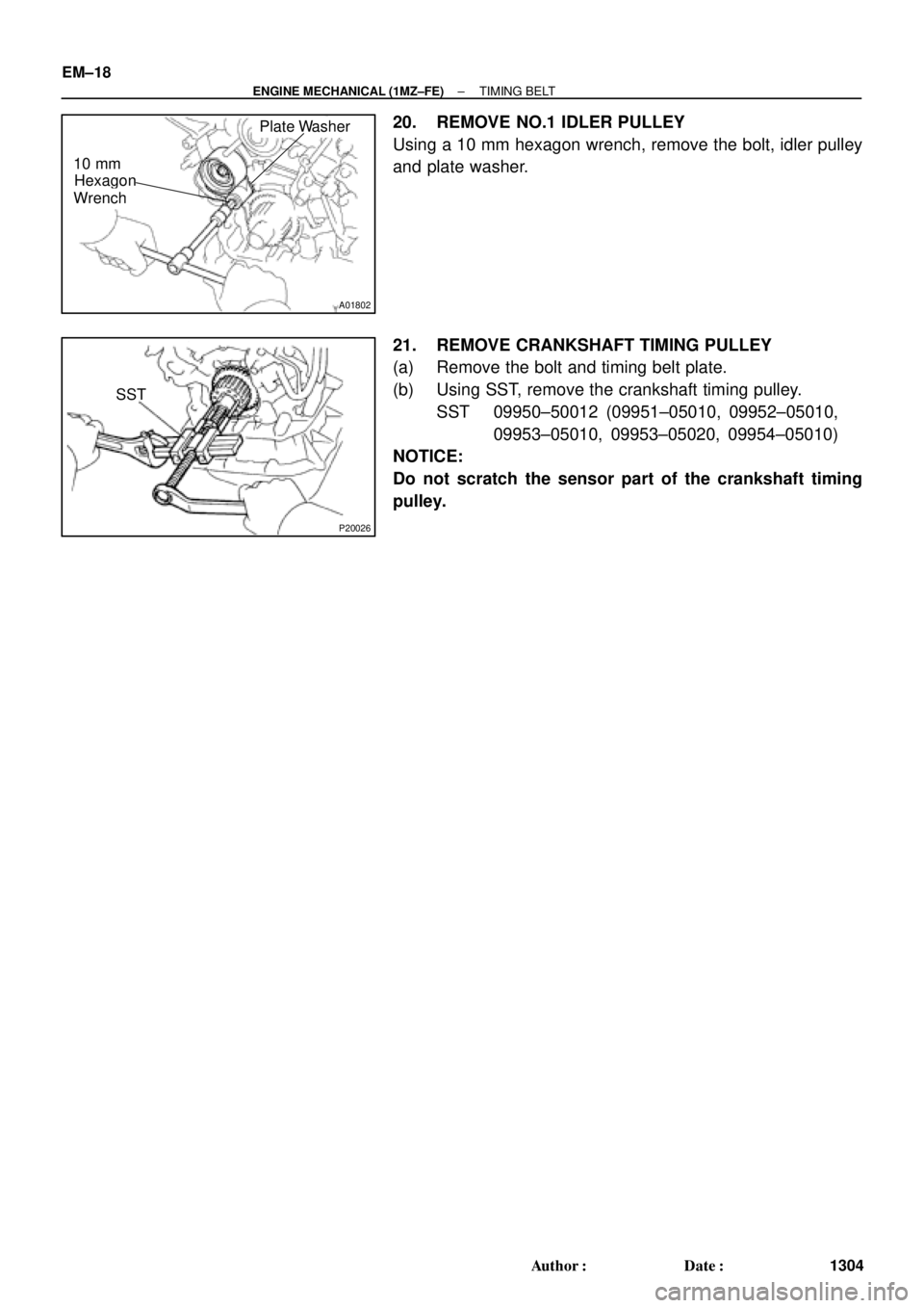
20. REMOVE NO.1 IDLER PULLEY
Using a 10 mm hexagon wrench, remove the bolt, idler pulley
and plate washer.
21. REMOVE CRANKSHAFT TIMING PULLEY
(a) Remove the bolt and timing belt plate.
(b) Using SST, remove the crankshaft timing pulley.
SST 09950±50012 (09951±05010, 09952±05010,
09953±05010, 09953±05020, 09954±05010)
NOTICE:
Do not scratch the sensor part of the crankshaft timing
pulley.