Page 2304 of 4592
D06505
ON
SPD
AT7809
4.5 ~ 5.5 V
0
Turn the wheel
DI±152
± DIAGNOSTICSAUTOMATIC TRANSAXLE
INSPECTION PROCEDURE
1 Check operation of speedometer.
CHECK:
Drive the vehicle and check if the operation of the speedmeter in the combination meter is normal.
HINT:
The vehicle speed sensor is operating normally if the speedometer display is normal.
NG Check speedometer circuit. See combination
meter troubleshooting (See page BE±4).
OK
2 Check voltage between terminal SPD of ECM connector and body ground.
PREPARATION:
(a) Remove glove compartment (See Pub. No. RM654U on
page BO±75).
(b) Shift the shift lever to neutral.
(c) Jack up one of the front wheels.
(d) Turn ignition switch to ON.
CHECK:
Measure voltage between terminal SPD of ECM connector and
body ground when the wheel is turned slowly.
OK:
Voltage is generated intermittently.
NG Check and repair harness and connector be-
tween combination meter and ECM (See page
IN±29).
OK
Page 2318 of 4592
D06504
Combination
Meter
R
C10
2
L8
11
6 C10
C10R±B
13
O
Y16IF1
IF1L±W
YInstrument
Panel J/BECM
1H
1V10
5
19
18
17
6 E4
E4
E4
E7R2 L
B
+
NSW Y
L±W
R±B A
J23J27
J24 CC R±B Park/Neutral
Position Switch
P1
8 3 4
P1
P1Y5
6
5
P1L±W
R±BJ22
Junction
Connector
EEE
J22 Junction
ConnectorD
D D
R±B 3
IG3
B±W
B±W B±W
B±W Junction
Connector
B
BB
J22
Junction
Connector 11
IG2 P12
P16
N RB
P RL2L LL
GR J19
Junction
Connector
D
DR±L
R±L 2R±L
IG2
F
F
J24 Junction
ConnectorR±L
1
1
1K 1JGAUGE
B±Y 24
I10 Ignition Switch
I10
I10 I107
8
R43
1K
1J STARTER Instrument Panel J/B
Instrument Panel J/B W
W±R AM1
1B
2L12
55 1B
1K 1K
2A 41
AM2 W±R
Instrument Panel J/B Instrument Panel J/B
Engine Room J/B No.2 12 F14 F14
ALT
11F9 F11B±RB±R
B±G
FL
MAIN
BatteryB
J7 J8 Junction Connector
10
GRCB
IG2J7 J6GR B
ST Relay
2B3
115
9
2J2D
2K 53
12 Engine Room J/B No.2
J9 Junction ConnectorStarter
A
IF MAIN IG2 IG2 DI±166
± DIAGNOSTICSAUTOMATIC TRANSAXLE
WIRING DIAGRAM
Page 2319 of 4592

D06387
(+)NSW
(±)2R
L
Position
P, N
R
D
2
LNSW±Body
groundR±Body
ground2±Body
groundL±Body
ground
0 V
0 V0 V0 V
0 V
0 V
0 V 0 V
0 V
0 V 0 V
0 V
0 V 9 ± 14 V*
9 ± 14 V
9 ± 14 V
9 ± 14 V 9 ± 14 V*
9 ± 14 V
9 ± 14 V
± DIAGNOSTICSAUTOMATIC TRANSAXLE
DI±167
INSPECTION PROCEDURE
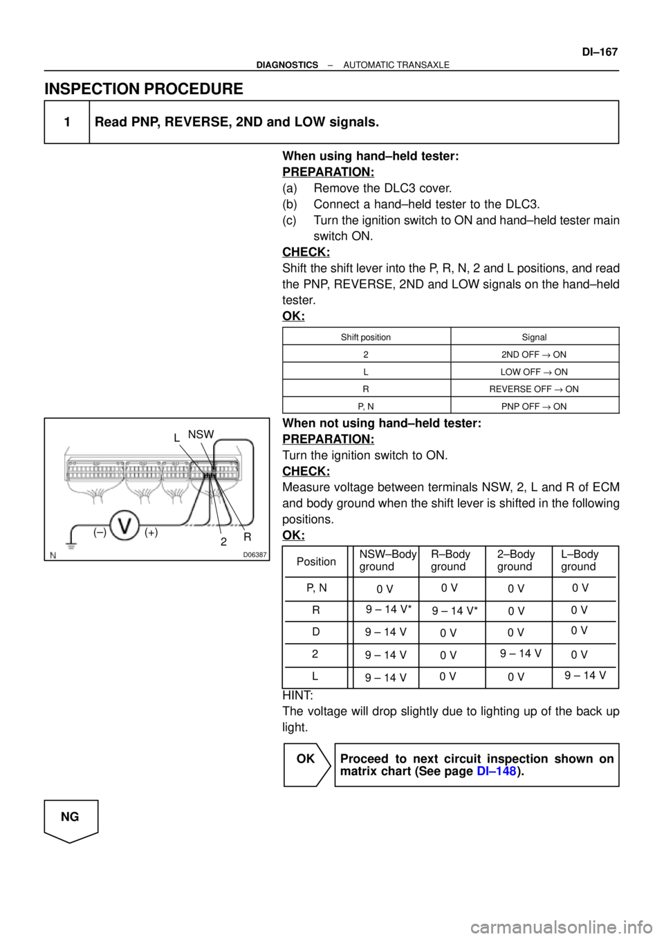
1 Read PNP, REVERSE, 2ND and LOW signals.
When using hand±held tester:
PREPARATION:
(a) Remove the DLC3 cover.
(b) Connect a hand±held tester to the DLC3.
(c) Turn the ignition switch to ON and hand±held tester main
switch ON.
CHECK:
Shift the shift lever into the P, R, N, 2 and L positions, and read
the PNP, REVERSE, 2ND and LOW signals on the hand±held
tester.
OK:
Shift positionSignal
22ND OFF " ON
LLOW OFF " ON
RREVERSE OFF " ON
P, NPNP OFF " ON
When not using hand±held tester:
PREPARATION:
Turn the ignition switch to ON.
CHECK:
Measure voltage between terminals NSW, 2, L and R of ECM
and body ground when the shift lever is shifted in the following
positions.
OK:
HINT:
The voltage will drop slightly due to lighting up of the back up
light.
OK Proceed to next circuit inspection shown on
matrix chart (See page DI±148).
NG
Page 2322 of 4592
BE3840
D05153D05153
ON
OD1 (+)
(±)
BE3840
I00143D00057
ON
OD (+) (±)
DI±170
± DIAGNOSTICSAUTOMATIC TRANSAXLE
INSPECTION PROCEDURE
1 Check voltage between terminal OD1 of ECM and body ground.
PREPARATION:
Turn the ignition switch to ON.
CHECK:
Measure voltage between terminal OD1 of ECM and body
ground.
OK:
Voltage: 9 ± 14 V
OK Proceed to next circuit inspection shown on
matrix chart (See page DI±148).
NG
2 Check voltage between terminal OD of cruise control ECU harness side connec-
tor and body ground.
PREPARATION:
(a) Disconnect the cruise control ECU connector.
(b) Turn the ignition switch to ON.
CHECK:
Measure voltage between terminal OD of cruise control ECU
harness side connector and body ground.
OK:
Voltage: 9 ± 14 V
OK Check and replace the cruise control ECU.
NG
3 Check harness and connector between cruise control ECU and ECM.
NG Repair or replace the harness or connector.
OK
Check and replace the ECM.
Page 2323 of 4592
D05150
ECM
B+
OD2
(*) O/D Main
Switch Instrument
Panel J/BIgnition Switch
J5
Junction
Connector
B±RAM1
G±O
E47 IF1 11
G±O
G±O
O2 2
O2 4C
C
C
W±B
J4
Junction
Connector
W±B A
A
IE G±O IG1I104
I102
W
IK2
AM1
IB 1
B±R
F14 1
F14 2
ALT
F9 1
B±G
FL
MAINInstrument Panel
J/B
GAUGE
O/D OFF
Indicator Light
(Combination Meter)
FUSIBLE
LINK
BLOCK
O/D Main Switch
Contacts go open with switch pushed in
contacts go closed with switch pushed once again1K1
1D2
R±L
R±L
Battery J3
Junction
Connector
DDC127
C1012
*:
± DIAGNOSTICSAUTOMATIC TRANSAXLE
DI±171
O/D Main Switch & O/D OFF Indictor Light Circuit
CIRCUIT DESCRIPTION
The O/D main switch contacts go open when the switch is pushed in and go closed when it is pushed out.
In O/D main switch in OFF position, the O/D OFF indicator light lights up, and the ECM prohibits shifting over-
drive.
WIRING DIAGRAM
DI1J1±04
Page 2325 of 4592
D05151BE3840D06388
ON
OD2
± DIAGNOSTICSAUTOMATIC TRANSAXLE
DI±173
3 Check OVERDRIVE CUT SW2 signal.
When using hand±held tester:
PREPARATION:
(a) Remove the DLC3 cover.
(b) Connect hand±held tester to the DLC3.
(c) Turn the ignition switch to ON and hand±held tester main
switch ON.
CHECK:
Read the OVRDRIVE CUT SW2 signal on the hand±held tester.
OK:
O/D main switch conditionOVRDRIVE CUT SW2 signal
O/D ON (Pushed in)OFF
O/D OFF (Pushed once again)ON
When not using hand±held tester:
PREPARATION:
Turn the ignition switch to ON.
CHECK:
Check voltage between terminal OD2 of ECM and body ground.
OK:
O/D main switch conditionVoltage
O/D ON (Pushed in)9 ± 14
O/D OFF (Pushed once again)Below 1.5 V
OK Check and replace the ECM (See page IN±29).
NG
4 Check harness and connector between O/D OFF indicator light and ECM (See
page IN±29).
NG Repair or replace the harness or connector.
OK
Check and replace the ECM (See page
IN±29).
Page 2329 of 4592

F00047
DI03C±04
F00006
DLC1Short Pin
S-17-1 Iei-23-1-A
F00041
DLC2 DLC1
Tc E1
E1Tc
R01346
Normal Code
0.25 sec.
0.25 sec. 2 sec.
ON
OFF
ON
OFF0.5 sec. 0.5 sec.
Code 11 and 21
4 sec.1.5 sec.
2.5 sec.
Code 11 Code 21
± DIAGNOSTICSANTI±LOCK BRAKE SYSTEM
DI±177
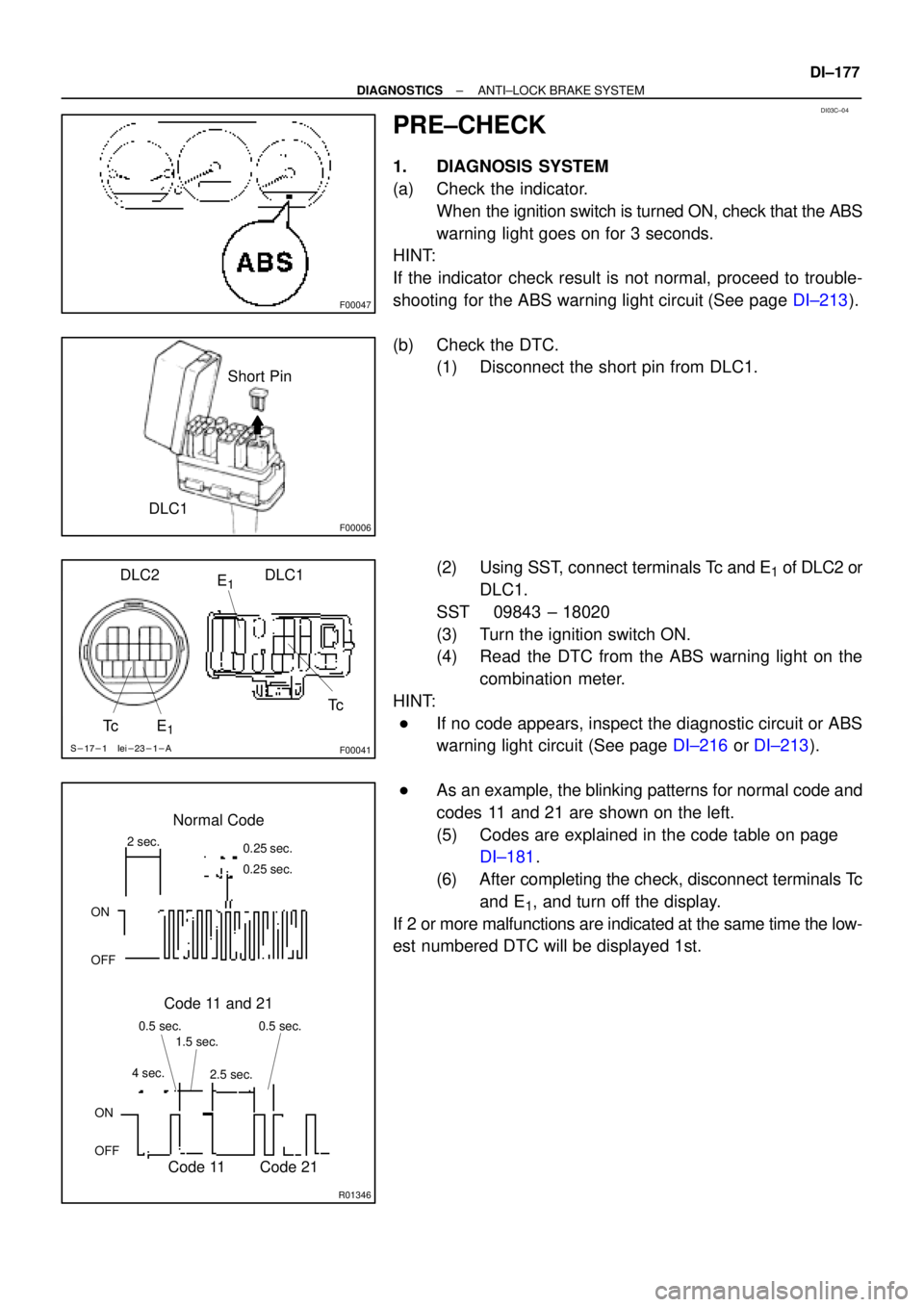
PRE±CHECK
1. DIAGNOSIS SYSTEM
(a) Check the indicator.
When the ignition switch is turned ON, check that the ABS
warning light goes on for 3 seconds.
HINT:
If the indicator check result is not normal, proceed to trouble-
shooting for the ABS warning light circuit (See page DI±213).
(b) Check the DTC.
(1) Disconnect the short pin from DLC1.
(2) Using SST, connect terminals Tc and E
1 of DLC2 or
DLC1.
SST 09843 ± 18020
(3) Turn the ignition switch ON.
(4) Read the DTC from the ABS warning light on the
combination meter.
HINT:
�If no code appears, inspect the diagnostic circuit or ABS
warning light circuit (See page DI±216 or DI±213).
�As an example, the blinking patterns for normal code and
codes 11 and 21 are shown on the left.
(5) Codes are explained in the code table on page
DI±181.
(6) After completing the check, disconnect terminals Tc
and E
1, and turn off the display.
If 2 or more malfunctions are indicated at the same time the low-
est numbered DTC will be displayed 1st.
Page 2330 of 4592

H07517
TOYOTA
Hand±held Tester
DLC2
BR3890
F00006DLC1Short Pin
N09348
Hand±held Tester
Break±out±boxECUTOYOTA
TOYOTA DI±178
± DIAGNOSTICSANTI±LOCK BRAKE SYSTEM
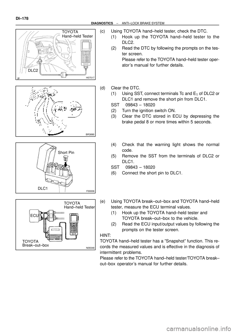
(c) Using TOYOTA hand±held tester, check the DTC.
(1) Hook up the TOYOTA hand±held tester to the
DLC2.
(2) Read the DTC by following the prompts on the tes-
ter screen.
Please refer to the TOYOTA hand±held tester oper-
ator 's manual for further details.
(d) Clear the DTC.
(1) Using SST, connect terminals Tc and E
1 of DLC2 or
DLC1 and remove the short pin from DLC1.
SST 09843 ± 18020
(2) Turn the ignition switch ON.
(3) Clear the DTC stored in ECU by depressing the
brake pedal 8 or more times within 5 seconds.
(4) Check that the warning light shows the normal
code.
(5) Remove the SST from the terminals of DLC2 or
DLC1.
SST 09843 ± 18020
(6) Connect the short pin to DLC1.
(e) Using TOYOTA break±out±box and TOYOTA hand±held
tester, measure the ECU terminal values.
(1) Hook up the TOYOTA hand±held tester and
TOYOTA break±out±box to the vehicle.
(2) Read the ECU input/output values by following the
prompts on the tester screen.
HINT:
TOYOTA hand±held tester has a ºSnapshotº function. This re-
cords the measured values and is effective in the diagnosis of
intermittent problems.
Please refer to the TOYOTA hand±held tester/TOYOTA break±
out±box operator's manual for further details.