Page 2376 of 4592

AT0716AB0056H08231
Normal Code
ON
OFF0.25
0.25
Code 11 and 31
ON
OFF
0.5 2.54.0
1.5 0.5
DTC 11
DTC 31Repeat
S05331
TOYOTA Hand±Held Tester
DLC3 DI±224
± DIAGNOSTICSSUPPLEMENTAL RESTRAINT SYSTEM
(c) Read the DTC.
Read the 2±digit DTC as indicated by the number of times
the SRS warning light blinks. As an example, the blinking
patterns, normal, 11 and 31 are shown in the illustration.
�Normal code indication
The light will blink 2 times per second.
�Malfunction code indication
The first blinking output indicates the first digit
of a 2±digit DTC. After a 1.5±second pause,
the second blinking output will indicate the
second digit.
If there are 2 or more codes, there will be a 2.5±second pause
between each code. After all the codes have been output, there
will be a 4.0±second pause and they will all be repeated.
HINT:
�In the event of a number of trouble codes, indication will
start from the smallest numbered code.
�If a DTC is not output or a DTC is output without terminal
connection, proceed to the Tc terminal circuit inspection
on page DI±313.
3. DTC CHECK (Using TOYOTA hand±held tester)
(a) Hook up the TOYOTA hand±held tester to the DLC3.
(b) Read the DTCs by following the prompts on the tester
screen.
HINT:
Please refer to the TOYOTA hand±held tester operator's manu-
al for further details.
4. DTC CLEARANCE (Not using service wire)
When the ignition switch is turned off, the diagnostic trouble
code is cleared.
HINT:
DTC might not be cleared by turning the ignition switch OFF.
In this case, proceed to the next step.
5. DTC CLEARANCE (Using service wire)
(a) Connect the 2 service wires to terminals Tc and AB of
DLC1.
(b) Turn the ignition switch to ACC or ON and wait for approx.
6 seconds.
Page 2385 of 4592
DI164±25
± DIAGNOSTICSSUPPLEMENTAL RESTRAINT SYSTEM
DI±233
PROBLEM SYMPTOMS TABLE
Proceed with troubleshooting of each circuit in the table below.
SymptomSuspect AreaSee page
�With the ignition switch in ACC or ON position, the SRS warning
light sometimes lights up after approx. 6 seconds have elapsed.�SRS warning light circuit
(Al li ht h i iti it h i i LOCK iDI 308�SRS warning light is always lit up even when ignition switch is in
the LOCK position.(Always lights up when ignition switch is in LOCK posi-
tion.)DI±308
�With the ignition switch in ACC or ON position, the SRS warning
light does not light up.�SRS warning light circuit
(Does not light up when ignition switch is turned to ACC or
ON.)
DI±308
�DTC is not displayed.
�SRS warning light is always lit up at the time of DTC check pro-
cedure.�Tc terminal circuitDI±313
�DTC is displayed without Tc and E1 terminal connection.
Page 2388 of 4592
FI1390AB0118
R13006AB0119H01002H07478
D SquibSpiral
Cable
Airbag
Sensor
Assembly
E1TcON
or
DTC B0100/13
DLC1"u
ACC
DI±236
± DIAGNOSTICSSUPPLEMENTAL RESTRAINT SYSTEM
3 Check airbag sensor assembly.
PREPARATION:
(a) Connect the connector to the airbag sensor assembly.
(b) Connect negative (±) terminal cable to the battery, and
wait at least for 2 seconds.
CHECK:
(a) Turn ignition switch to ACC or ON and wait at least for 20
seconds.
(b) Clear DTC stored in memory (See page DI±223).
(c) Turn ignition switch to LOCK, and wait at least for 20 se-
conds.
(d) Turn ignition switch to ACC or ON, and wait at least for 20
seconds.
(e) Check DTC (See page DI±223).
OK:
DTC B0100/13 is not output.
HINT:
Codes other than code B0100/13 may be output at this time, but
they are not relevant to this check.
NG Replace airbag sensor assembly.
OK
Page 2389 of 4592

AB0118
R13006AB0119FI1390
H01003H01136
D SquibSpiral
CableAirbag
Sensor
Assembly
E1 TcACC ON
or
DTC B0100/13
DLC1
" u
± DIAGNOSTICSSUPPLEMENTAL RESTRAINT SYSTEM
DI±237
4 Check D squib.
PREPARATION:
(a) Turn ignition switch to LOCK.
(b) Disconnect negative (±) terminal cable from the battery,
and wait at least for 90 seconds.
(c) Connect the steering wheel pad connector.
(d) Connect negative (±) terminal cable to the battery, and
wait at least for 2 seconds.
CHECK:
(a) Turn ignition switch to LOCK, and wait at least for 20 se-
conds.
(b) Turn ignition switch to ACC or ON, and wait at least for 20
seconds.
(c) Clear DTC stored in memory (See page DI±223).
(d) Turn ignition switch to LOCK, and wait at least for 20 se-
conds.
(e) Turn ignition switch to ACC or ON, and wait at least for 20
seconds.
(f) Check DTC (See page DI±223).
OK:
DTC B0100/13 is not output.
HINT:
Codes other than code B0100/13 may be output at this time, but
they are not relevant to this check.
NG Replace steering wheel pad.
OK
From the results of the above inspection, the malfunctioning part can now be considered normal.
To make sure of this, use the simulation method to check.
Page 2392 of 4592

AB0118
R13006AB0069
AB0119W02044
H01002
H01140
D SquibSpiral
CableAirbag
Sensor
Assembly
E1TcACCON
or
DTC B0101/14 DLC1"u
D+D±
DI±240
± DIAGNOSTICSSUPPLEMENTAL RESTRAINT SYSTEM
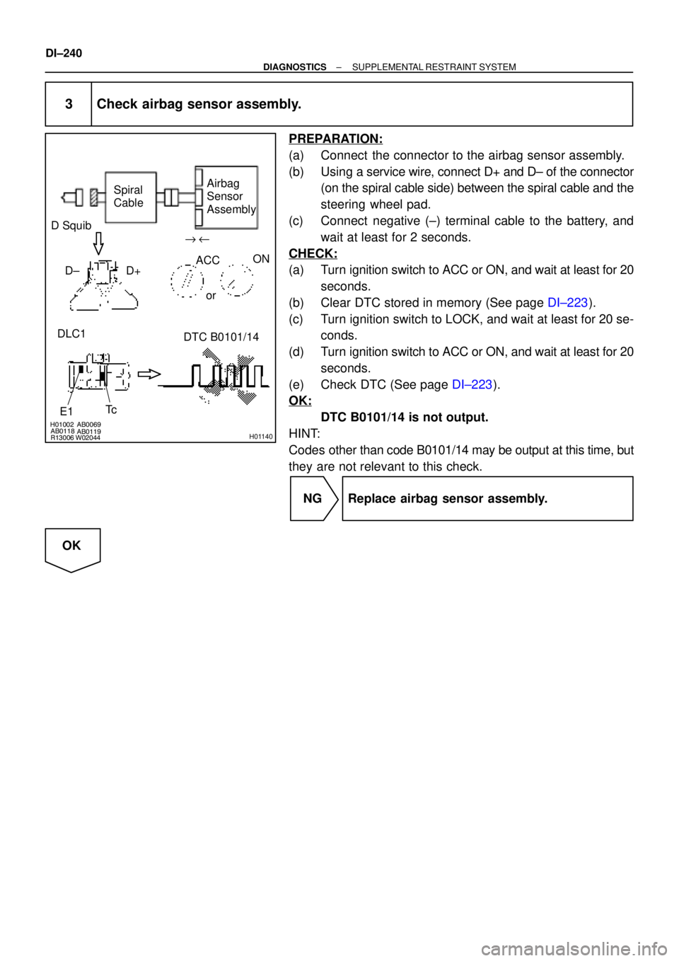
3 Check airbag sensor assembly.
PREPARATION:
(a) Connect the connector to the airbag sensor assembly.
(b) Using a service wire, connect D+ and D± of the connector
(on the spiral cable side) between the spiral cable and the
steering wheel pad.
(c) Connect negative (±) terminal cable to the battery, and
wait at least for 2 seconds.
CHECK:
(a) Turn ignition switch to ACC or ON, and wait at least for 20
seconds.
(b) Clear DTC stored in memory (See page DI±223).
(c) Turn ignition switch to LOCK, and wait at least for 20 se-
conds.
(d) Turn ignition switch to ACC or ON, and wait at least for 20
seconds.
(e) Check DTC (See page DI±223).
OK:
DTC B0101/14 is not output.
HINT:
Codes other than code B0101/14 may be output at this time, but
they are not relevant to this check.
NG Replace airbag sensor assembly.
OK
Page 2393 of 4592

W02044
H01003AB0118
R13006AB0119H01141
"u D Squib
Spiral
CableAirbag
Sensor
Assembly
E1TcACCON
or
DTC B0101/14 DLC1
± DIAGNOSTICSSUPPLEMENTAL RESTRAINT SYSTEM
DI±241
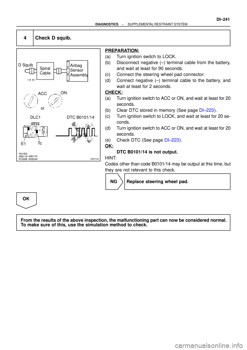
4 Check D squib.
PREPARATION:
(a) Turn ignition switch to LOCK.
(b) Disconnect negative (±) terminal cable from the battery,
and wait at least for 90 seconds.
(c) Connect the steering wheel pad connector.
(d) Connect negative (±) terminal cable to the battery, and
wait at least for 2 seconds.
CHECK:
(a) Turn ignition switch to ACC or ON, and wait at least for 20
seconds.
(b) Clear DTC stored in memory (See page DI±223).
(c) Turn ignition switch to LOCK, and wait at least for 20 se-
conds.
(d) Turn ignition switch to ACC or ON, and wait at least for 20
seconds.
(e) Check DTC (See page DI±223).
OK:
DTC B0101/14 is not output.
HINT:
Codes other than code B0101/14 may be output at this time, but
they are not relevant to this check.
NG Replace steering wheel pad.
OK
From the results of the above inspection, the malfunctioning part can now be considered normal.
To make sure of this, use the simulation method to check.
Page 2396 of 4592

H01002W01933
AB0118
R13006AB0069
AB0118
W02042H01127
D SquibSpiral
Cable
Airbag
Sensor
Assembly
D+
E1D±
TcACC ON
or
DTC B0102/11 DLC1"u
DI±244
± DIAGNOSTICSSUPPLEMENTAL RESTRAINT SYSTEM
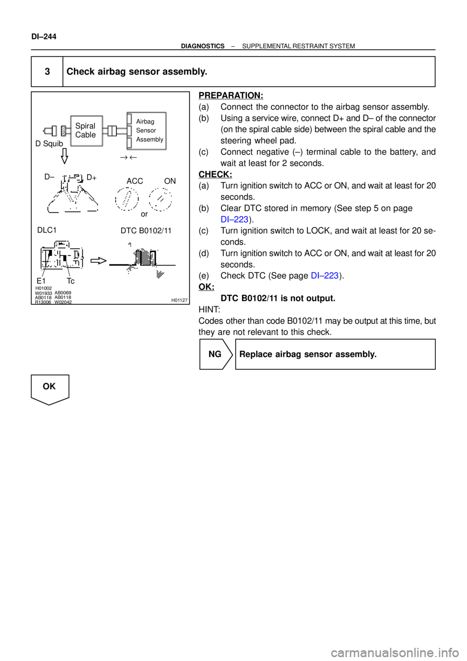
3 Check airbag sensor assembly.
PREPARATION:
(a) Connect the connector to the airbag sensor assembly.
(b) Using a service wire, connect D+ and D± of the connector
(on the spiral cable side) between the spiral cable and the
steering wheel pad.
(c) Connect negative (±) terminal cable to the battery, and
wait at least for 2 seconds.
CHECK:
(a) Turn ignition switch to ACC or ON, and wait at least for 20
seconds.
(b) Clear DTC stored in memory (See step 5 on page
DI±223).
(c) Turn ignition switch to LOCK, and wait at least for 20 se-
conds.
(d) Turn ignition switch to ACC or ON, and wait at least for 20
seconds.
(e) Check DTC (See page DI±223).
OK:
DTC B0102/11 is not output.
HINT:
Codes other than code B0102/11 may be output at this time, but
they are not relevant to this check.
NG Replace airbag sensor assembly.
OK
Page 2397 of 4592

H01003AB0118
R13006AB0119
W02042H01128
D SquibSpiral
Cable
Airbag
Sensor
Assembly
E1Tc ACC ON
or
DTC B0102/11 DLC1" u
± DIAGNOSTICSSUPPLEMENTAL RESTRAINT SYSTEM
DI±245
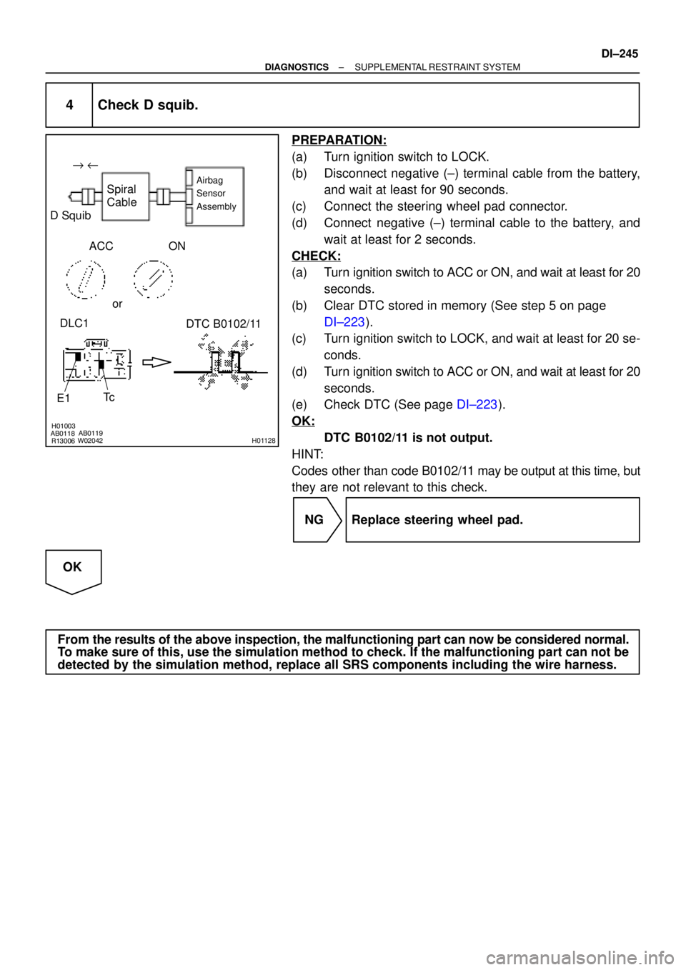
4 Check D squib.
PREPARATION:
(a) Turn ignition switch to LOCK.
(b) Disconnect negative (±) terminal cable from the battery,
and wait at least for 90 seconds.
(c) Connect the steering wheel pad connector.
(d) Connect negative (±) terminal cable to the battery, and
wait at least for 2 seconds.
CHECK:
(a) Turn ignition switch to ACC or ON, and wait at least for 20
seconds.
(b) Clear DTC stored in memory (See step 5 on page
DI±223).
(c) Turn ignition switch to LOCK, and wait at least for 20 se-
conds.
(d) Turn ignition switch to ACC or ON, and wait at least for 20
seconds.
(e) Check DTC (See page DI±223).
OK:
DTC B0102/11 is not output.
HINT:
Codes other than code B0102/11 may be output at this time, but
they are not relevant to this check.
NG Replace steering wheel pad.
OK
From the results of the above inspection, the malfunctioning part can now be considered normal.
To make sure of this, use the simulation method to check. If the malfunctioning part can not be
detected by the simulation method, replace all SRS components including the wire harness.