Page 1713 of 4592

DI±501
736 Author�: Date�:
PROBLEM SYMPTOMS TABLE
If a normal code is displayed during the DTC check but the problem still occurs, check t")
DI03G±04
± DIAGNOSTICSANTI±LOCK BRAKE SYSTEM (DENSO Made)
DI±501
736 Author�: Date�:
PROBLEM SYMPTOMS TABLE
If a normal code is displayed during the DTC check but the problem still occurs, check the circuits for each
problem symptom in the order given in the table below and proceed to the relevant troubleshooting page.
SymptomSuspect AreaSee page
ABS does not operate
Only when 1. to 4. are all normal and the problem is still
occurring, replace the ABS ECU.
13.Check the DTC reconfirming that the normal code is
output.
14.IG power source circuit.
15.Speed sensor circuit.
16.Check the ABS actuator with a checker.
If abnormal, check the hydraulic circuit for leakage
(See page DI±536).
DI±493
DI±520
DI±514
BR±50
ABS does not operate efficiently
Only when 1. to 4. are all normal and the problem is still
occurring, replace the ABS ECU.
1. Check the DTC reconfirming that the normal code is
output.
2. Speed sensor circuit
3. Stop light switch circuit
4. Check the ABS actuator with a checker.
If abnormal, check the hydraulic circuit for leakage
(See page DI±536).
DI±493
DI±514
DI±523
BR±50
ABS warning light abnormal1. ABS warning light circuit
2. ABS ECUDI±529
DI±527
DTC check cannot be done
Only when 1. and 2. are all normal and the problem is still
occurring, replace the ABS ECU.
1. ABS warning light circuit
2. Tc terminal circuit
DI±529
DI±532
Speed sensor signal check cannot be done1. Ts terminal circuit
2. ABS ECUDI±534
DI±527
Page 1726 of 4592

749 Author�: Date�:
DTC31, 32, 33, 34Speed Sensor Circu")
BR3583
BR3582F00010
RotorSpeed Sensor
Magnet
To ECU
+V
±VHigh Speed
Low Speed
CoilNS
DI±514
± DIAGNOSTICSANTI±LOCK BRAKE SYSTEM (DENSO Made)
749 Author�: Date�:
DTC31, 32, 33, 34Speed Sensor Circuit
CIRCUIT DESCRIPTION
The speed sensor detects wheel speed and sends the ap-
propriate signals to the ECU. These signals are used to control
the ABS system. The front and rear rotors each have 48 serra-
tions.
When the rotors rotate, the magnetic field emitted by the perma-
nent magnet in the speed sensor generates an AC voltage.
Since the frequency of this AC voltage changes in direct propor-
tion to the speed of the rotor, the frequency is used by the ECU
to detect the speed of each wheel.
DTC No.DTC Detecting ConditionTrouble Area
31, 32, 33, 34
Detection of any of conditions from 1. through 4.:
1. Vehicle speed is at 10 km/h (6 mph) or more and the
speed sensor signal circuit is open or short circuit con-
tinues for 15 sec. or more.
2. Momentary interruption of the speed sensor signal oc-
curs 7 times or more.
3. Vehicle speed is at 20 km/h (12mph) or more and inter-
ference on the speed sensor signal continues for 5 sec.
or more.
4. Open circuit condition of the speed sensor signal circuit
continues for 0.5 sec. or more.
�Right front, left front, right rear, left rear speed sensor
�Each speed sensor circuit
�Speed sensor rotor
HINT:
�DTC No. 31 is for the right front speed sensor.
�DTC No. 32 is for the left front speed sensor.
�DTC No. 33 is for the right rear speed sensor.
�DTC No. 34 is for the left rear speed sensor.
Fail safe function:
If trouble occurs in the speed sensor circuit, the ECU cuts off current to the ABS solenoid relay and prohibits
ABS control.
DI1JM±02
Page 1727 of 4592
F00116
Right Front
Speed Sensor
Left Front
Speed Sensor
Right Rear
Speed Sensor
Left Rear
Speed Sensor2
1A18
A19 12
1
2
2 1A18
A18
A18
A19
A19
A19ABS ECU
W
B
R
G
B
G RB WG R
IK2
IL1
ID1IK2
ID1 IL11
6
2
1
3
983
FR+
FR±
FL+
FL±
RR+
RR±
RL+
RL±Right Front
Speed Sensor
Left Front
Speed Sensor
Left Rear
Speed Sensor2
1A18
A19 12
1
2
2 1A18
A18
A18
A19
A19
A19ABS ECU
W
B
R
G
W
G RB WG R
IK2
IL1
ID1IK2
ID1 IL11
6
2
1
3
99
93
FR+
FR±
FL+
FL±
RR+
RR±
RL+
RL± 2
10
23
R
G22
± DIAGNOSTICSANTI±LOCK BRAKE SYSTEM (DENSO Made)
DI±515
750 Author�: Date�:
WIRING DIAGRAM
Page 1728 of 4592
R14205
1
2
R14213
12 12
12
12
12
1212
DI±516
± DIAGNOSTICSANTI±LOCK BRAKE SYSTEM (DENSO Made)
751 Author�: Date�:
INSPECTION PROCEDURE
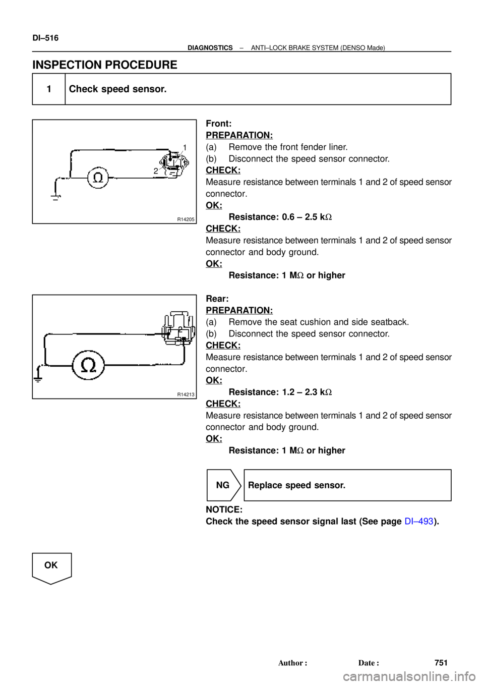
1 Check speed sensor.
Front:
PREPARATION:
(a) Remove the front fender liner.
(b) Disconnect the speed sensor connector.
CHECK:
Measure resistance between terminals 1 and 2 of speed sensor
connector.
OK:
Resistance: 0.6 ± 2.5 kW
CHECK:
Measure resistance between terminals 1 and 2 of speed sensor
connector and body ground.
OK:
Resistance: 1 MW or higher
Rear:
PREPARATION:
(a) Remove the seat cushion and side seatback.
(b) Disconnect the speed sensor connector.
CHECK:
Measure resistance between terminals 1 and 2 of speed sensor
connector.
OK:
Resistance: 1.2 ± 2.3 kW
CHECK:
Measure resistance between terminals 1 and 2 of speed sensor
connector and body ground.
OK:
Resistance: 1 MW or higher
NG Replace speed sensor.
NOTICE:
Check the speed sensor signal last (See page DI±493).
OK
Page 1729 of 4592
BR3795
OK NG OK NG
OK NGOK NG
W04200
Normal Signal Waveform
1 V / Division2 m/s / DivisionGND
± DIAGNOSTICSANTI±LOCK BRAKE SYSTEM (DENSO Made)
DI±517
752 Author�: Date�:
2 Check for open and short circuit in harness and connector between each speed
sensor and ECU (See page IN±31).
NG Repair or replace harness or connector.
OK
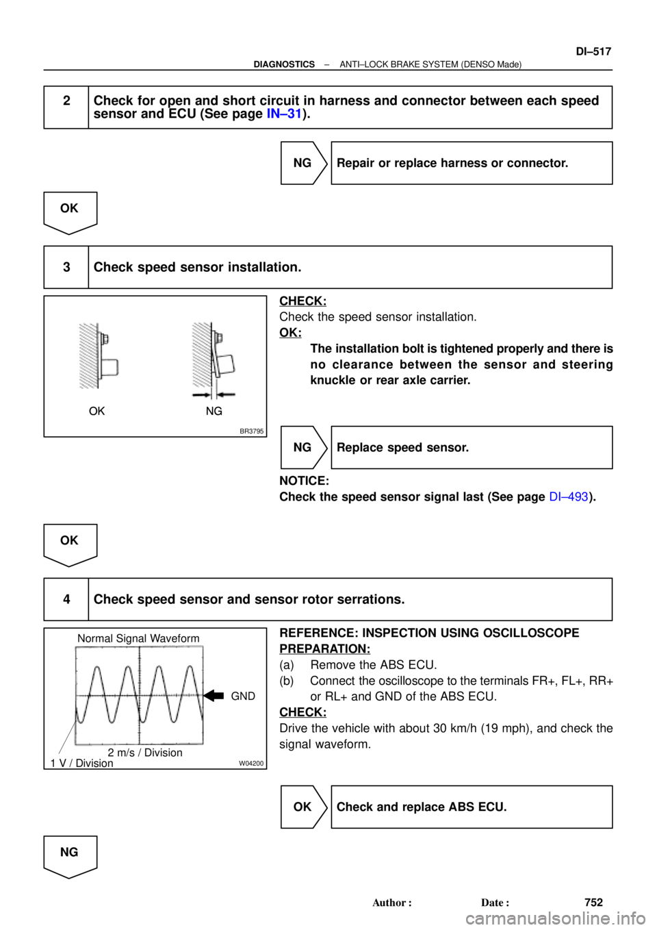
3 Check speed sensor installation.
CHECK:
Check the speed sensor installation.
OK:
The installation bolt is tightened properly and there is
no clearance between the sensor and steering
knuckle or rear axle carrier.
NG Replace speed sensor.
NOTICE:
Check the speed sensor signal last (See page DI±493).
OK
4 Check speed sensor and sensor rotor serrations.
REFERENCE: INSPECTION USING OSCILLOSCOPE
PREPARATION:
(a) Remove the ABS ECU.
(b) Connect the oscilloscope to the terminals FR+, FL+, RR+
or RL+ and GND of the ABS ECU.
CHECK:
Drive the vehicle with about 30 km/h (19 mph), and check the
signal waveform.
OK Check and replace ABS ECU.
NG
Page 1730 of 4592
R00948
R00947
DI±518
± DIAGNOSTICSANTI±LOCK BRAKE SYSTEM (DENSO Made)
753 Author�: Date�:
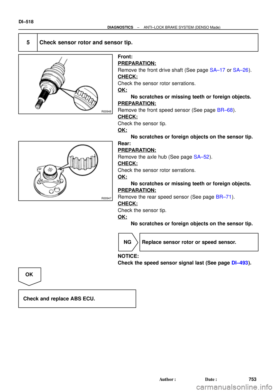
5 Check sensor rotor and sensor tip.
Front:
PREPARATION:
Remove the front drive shaft (See page SA±17 or SA±26).
CHECK:
Check the sensor rotor serrations.
OK:
No scratches or missing teeth or foreign objects.
PREPARATION:
Remove the front speed sensor (See page BR±68).
CHECK:
Check the sensor tip.
OK:
No scratches or foreign objects on the sensor tip.
Rear:
PREPARATION:
Remove the axle hub (See page SA±52).
CHECK:
Check the sensor rotor serrations.
OK:
No scratches or missing teeth or foreign objects.
PREPARATION:
Remove the rear speed sensor (See page BR±71).
CHECK:
Check the sensor tip.
OK:
No scratches or foreign objects on the sensor tip.
NG Replace sensor rotor or speed sensor.
NOTICE:
Check the speed sensor signal last (See page DI±493).
OK
Check and replace ABS ECU.
Page 1731 of 4592
± DIAGNOSTICSANTI±LOCK BRAKE SYSTEM (DENSO Made)
DI±519
754 Author�: Date�:
DTC 33, 34 Rear Speed Sensor Rotor Faulty
CIRCUIT DESCRIPTION
DTC No.DTC Detecting ConditionTrouble Area
33, 34
The condition that the both rear side wheels' speed is
lower than the front wheels' speed at 20 km/h (12 mph) or
more for 20 sec. or more when the IG switch turns ON
and OFF , which is repeated in a sequence more than 8
times.
�Rear axle hub
�Right rear, left rear speed sensor
�Rear speed sensor circuit
INSPECTION PROCEDURE
1 Check rear axle hub (See page SA±9).
NG Replace rear axle hub.
OK
2 Check rear speed sensor (See page DI±514).
NG Replace rear speed sensor.
OK
3 Check for open and short circuit in harness and connector between rear speed
sensor and ECU (See page IN±31).
NG Repair or replace harness and connector.
OK
Check and replace ABS ECU.
DI03L±03
Page 1735 of 4592

F00124
Battery MAIN B±GF4 F91
ALT FL Block
B±R STOP Instrument Panel J/B
1C1B4
7Stop Light
Switch
2G±W
1R 1S5J27 J28J/C
Light Failure
Sensor
J/C
J40
BL
BP W±BG±W
A195
STPABS ECU
R
G±R
High
Mounted
Stop
LightRight
Stop
LightLeft
Stop
Light
A 1Instrument
Panel J/B
G±R W
11R
2 4
G±W
G±R
W±B
W±B
W±B AAC
W±B W±BH10 R11
R9
H10R9
R11 2
122
5 5 G±W
1
2 7
Under the
Left Center
PillarBack Panel
Center
± DIAGNOSTICSANTI±LOCK BRAKE SYSTEM (DENSO Made)
DI±523
758 Author�: Date�:
DTC 49 Stop Light Switch Circuit
CIRCUIT DESCRIPTION
DTC No.DTC Detecting ConditionTrouble Area
49
ABS ECU terminal IG1 voltage is 9.5 V to 18.5 V and ABS
is in non±operation, the open circuit of the stop light switch
circuit continues for 0.3 sec. or more.�Stop light switch
�Stop light switch circuit
WIRING DIAGRAM
INSPECTION PROCEDURE
1 Check operation of stop light.
CHECK:
Check that stop light lights up when brake pedal is depressed and turns off when brake pedal is released.
NG Repair stop light circuit (See page BE±37).
OK
DI03N±03