Page 1746 of 4592
F00172
J/C
EC BRA
ABR
3
16 DLC1
Ts E
1
R±Y
II38
R±Y
A198
TsABS ECU
J22: (1MZ±FE)
J23: (5S±FE)
J/C
BRA
ABR
3
16 DLC1
Ts E
1
R±Y
II38
R±Y
A198
TsABS ECU
J22: (1MZ±FE)
J23: (5S±FE)
AB0119S08096
F00446DLC1 DLC1
DLC1
DLC1DLC1
Ts
DLC1 E1
ON
DI±534
± DIAGNOSTICSANTI±LOCK BRAKE SYSTEM (DENSO Made)
769 Author�: Date�:
Ts Terminal Circuit
CIRCUIT DESCRIPTION
The sensor check circuit detects abnormalities in the speed sensor signal which cannot be detected with
the DTC check.
Connecting terminals Ts and E
1 of the DLC1 in the engine compartment starts the check.
WIRING DIAGRAM
INSPECTION PROCEDURE
1 Check voltage between terminals Ts and E1 of DLC1.
CHECK:
(a) Turn the ignition switch ON.
(b) Measure voltage between terminals Ts and E
1 of DLC1.
OK:
Voltage: 10 ± 14 V
OK If ABS warning light does not blink even after Ts
and E
1 are connected, the ECU may be defec-
tive.
NG
DI03S±03
Page 1749 of 4592
DI051±04
Vehicle Brought to Workshop
Customer Problem Analysis
P. DI±538
Check and Clear DTC (Precheck)
P.
DI±539
Items inside
are titles of pages in this manual,
with the page number in the bottom portion. See
the pages for detailed explanations.
Problem Symptom ConfirmationSymptom Simulation
P. IN±21
Symptom
does not occur
Symptom
occurs
DTC Check
P. DI±539
Sensor CheckCircuit Inspection
P. DI±546 ~ DI±569
DTC Chart
P. DI±542 Malfunction codeProblem Symptoms Table
P. DI±545
Check for Fluid Leakage
P. DI±571
Identification of Problem
Normal code
Repair
Confirmation Test
End
1
2
3
4
5
67
89
10
11
Step 2, 5, 9, 11:Diagnostic steps permitting the use of the
TOYOTA hand±held tester.
± DIAGNOSTICSANTI±LOCK BRAKE SYSTEM (BOSCH Made)
DI±537
772 Author�: Date�:
ANTI±LOCK BRAKE SYSTEM (BOSCH Made)
HOW TO PROCEED WITH TROUBLESHOOTING
Troubleshoot in accordance with the procedure on the following pages.
Page 1752 of 4592

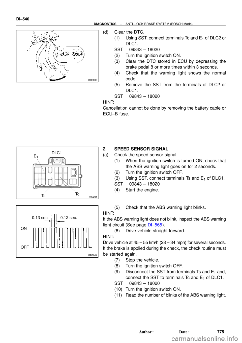
BR3890
F02201
DLC1
TsTc E1
BR3904
0.13 sec. 0.12 sec.
ON
OFF DI±540
± DIAGNOSTICSANTI±LOCK BRAKE SYSTEM (BOSCH Made)
775 Author�: Date�:
(d) Clear the DTC.
(1) Using SST, connect terminals Tc and E
1 of DLC2 or
DLC1.
SST 09843 ± 18020
(2) Turn the ignition switch ON.
(3) Clear the DTC stored in ECU by depressing the
brake pedal 8 or more times within 3 seconds.
(4) Check that the warning light shows the normal
code.
(5) Remove the SST from the terminals of DLC2 or
DLC1.
SST 09843 ± 18020
HINT:
Cancellation cannot be done by removing the battery cable or
ECU±B fuse.
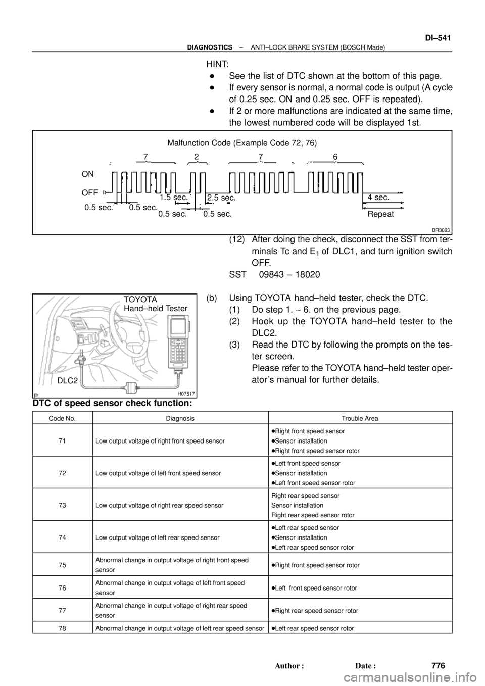
2. SPEED SENSOR SIGNAL
(a) Check the speed sensor signal.
(1) When the ignition switch is turned ON, check that
the ABS warning light goes on for 2 seconds.
(2) Turn the ignition switch OFF.
(3) Using SST, connect terminals Ts and E
1 of DLC1.
SST 09843 ± 18020
(4) Start the engine.
(5) Check that the ABS warning light blinks.
HINT:
If the ABS warning light does not blink, inspect the ABS warning
light circuit (See page DI±565).
(6) Drive vehicle straight forward.
HINT:
Drive vehicle at 45 ± 55 km/h (28 ± 34 mph) for several seconds.
If the brake is applied during the check, the check routine must
be started again.
(7) Stop the vehicle.
(8) Turn the ignition switch OFF.
(9) Disconnect the SST from terminals Ts and E
1 and,
connect the SST to terminals Tc and E
1 of DLC1.
SST 09843 ± 18020
(10) Turn the ignition switch ON.
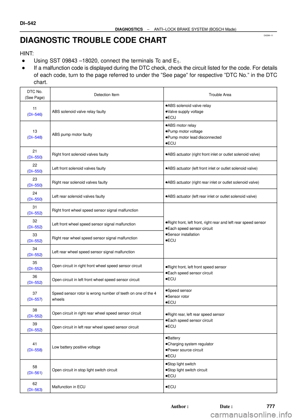
(11) Read the number of blinks of the ABS warning light.
Page 1753 of 4592

BR3893
Malfunction Code (Example Code 72, 76)
72 67
ON
OFF
0.5 sec. 0.5 sec. 0.5 sec. 0.5 sec.1.5 sec.
2.5 sec.4 sec.
Repeat
H07517
TOYOTA
Hand±held Tester
DLC2
± DIAGNOSTICSANTI±LOCK BRAKE SYSTEM (BOSCH Made)
DI±541
776 Author�: Date�:
HINT:
�See the list of DTC shown at the bottom of this page.
�If every sensor is normal, a normal code is output (A cycle
of 0.25 sec. ON and 0.25 sec. OFF is repeated).
�If 2 or more malfunctions are indicated at the same time,
the lowest numbered code will be displayed 1st.
(12) After doing the check, disconnect the SST from ter-
minals Tc and E
1 of DLC1, and turn ignition switch
OFF.
SST 09843 ± 18020
(b) Using TOYOTA hand±held tester, check the DTC.
(1) Do step 1. ~ 6. on the previous page.
(2) Hook up the TOYOTA hand±held tester to the
DLC2.
(3) Read the DTC by following the prompts on the tes-
ter screen.
Please refer to the TOYOTA hand±held tester oper-
ator 's manual for further details.
DTC of speed sensor check function:
Code No.DiagnosisTrouble Area
71Low output voltage of right front speed sensor
�Right front speed sensor
�Sensor installation
�Right front speed sensor rotor
72Low output voltage of left front speed sensor
�Left front speed sensor
�Sensor installation
�Left front speed sensor rotor
73Low output voltage of right rear speed sensor
Right rear speed sensor
Sensor installation
Right rear speed sensor rotor
74Low output voltage of left rear speed sensor
�Left rear speed sensor
�Sensor installation
�Left rear speed sensor rotor
75Abnormal change in output voltage of right front speed
sensor�Right front speed sensor rotor
76Abnormal change in output voltage of left front speed
sensor�Left front speed sensor rotor
77Abnormal change in output voltage of right rear speed
sensor�Right rear speed sensor rotor
78Abnormal change in output voltage of left rear speed sensor�Left rear speed sensor rotor
Page 1754 of 4592

DI03W±11
DI±542
± DIAGNOSTICSANTI±LOCK BRAKE SYSTEM (BOSCH Made)
777 Author�: Date�:
DIAGNOSTIC TROUBLE CODE CHART
HINT:
�Using SST 09843 ±18020, connect the terminals Tc and E1.
�If a malfunction code is displayed during the DTC check, check the circuit listed for the code. For details
of each code, turn to the page referred to under the ºSee pageº for respective ºDTC No.º in the DTC
chart.
DTC No.
(See Page)Detection ItemTrouble Area
11
(DI±546)ABS solenoid valve relay faulty
�ABS solenoid valve relay
�Valve supply voltage
�ECU
13
(DI±548)ABS pump motor faulty
�ABS motor relay
�Pump motor voltage
�Pump motor lead disconnected
�ECU
21
(DI±550)Right front solenoid valves faulty�ABS actuator (right front inlet or outlet solenoid valve)
22
(DI±550)Left front solenoid valves faulty�ABS actuator (left front inlet or outlet solenoid valve)
23
(DI±550)Right rear solenoid valves faulty�ABS actuator (right rear inlet or outlet solenoid valve)
24
(DI±550)Left rear solenoid valves faulty�ABS actuator (left rear inlet or outlet solenoid valve)
31
(DI±552)Right front wheel speed sensor signal malfunction
32
(DI±552)Left front wheel speed sensor signal malfunction�Right front, left front, right rear and left rear speed sensor
�Each speed sensor circuit
33
(DI±552)Right rear wheel speed sensor signal malfunction
�Each s eed sensor circuit
�Sensor installation
�ECU
34
(DI±552)Left rear wheel speed sensor signal malfunction
35
(DI±552)Open circuit in right front wheel speed sensor circuit�Right front, left front speed sensor
Eh d i it36
(DI±552)Open circuit in left front wheel speed sensor circuit
�Each speed sensor circuit
�ECU
37
(DI±557)Speed sensor rotor is wrong number of teeth on one of the 4
wheels�Speed sensor
�Sensor rotor
�ECU
38
(DI±552)Open circuit in right rear wheel speed sensor circuit�Right rear, left rear speed sensor
Eh d i it39
(DI±552)Open circuit in left rear wheel speed sensor circuit
�Each speed sensor circuit
�ECU
41
(DI±558)Low battery positive voltage
�Battery
�Charging system regulator
�Power source circuit
�ECU
58
(DI±561)Open circuit in stop light switch circuit
�Stop light switch
�Stop light switch circuit
�ECU
62
(DI±563)Malfunction in ECU�ECU
Page 1755 of 4592
DI03X±05
F01175
ABS Actuator
(w/ ECU, Relay)Front Speed Sensor
DLC1
DLC2Sensor Rotor
Rear Speed Sensor
Stop Light Switch ABS Warning Light
Sensor Rotor
Front Speed Sensor
± DIAGNOSTICSANTI±LOCK BRAKE SYSTEM (BOSCH Made)
DI±543
778 Author�: Date�:
PARTS LOCATION
Page 1757 of 4592

DI03Z±10
± DIAGNOSTICSANTI±LOCK BRAKE SYSTEM (BOSCH Made)
DI±545
780 Author�: Date�:
PROBLEM SYMPTOMS TABLE
If a normal code is displayed during the DTC check but the problem still occurs, check the circuits for each
problem symptom in the order given in the table below and proceed to the relevant troubleshooting page.
SymptomSuspect AreaSee page
ABS does not operate
Only when 1. to 4. are all normal and the problem is still
occurring, replace the ABS ECU.
1. Check the DTC reconfirming that the normal code is
output.
2. Power source circuit
3. Speed sensor circuit
4. Check the hydraulic circuit for leakage.
DI±539
DI±558
DI±552
DI±571
ABS does not operate intermittently
Only when 1. to 4. are all normal and the problem is still
occurring, replace the ABS ECU.
1. Check the DTC reconfirming that the normal code is
output.
2. Speed sensor circuit
3. Stop light switch circuit
4. Check the hydraulic circuit for leakage.
DI±539
DI±552
DI±561
DI±571
ABS warning light abnormal1. ABS warning light circuit
2. ABS ECUDI±565
DI±563
DTC check cannot be done
Only when 1. and 2. are all normal and the problem is still
occurring, replace the ABS ECU.
1. ABS warning light circuit
2. Tc terminal circuit
DI±565
DI±567
Speed sensor signal check cannot be done1. Ts terminal circuit
2. ABS ECUDI±569
DI±563
Page 1764 of 4592

BR3583
BR3582F00010
RotorSpeed Sensor
Magnet
To ECU
+V
±VHigh Speed
Low Speed
CoilNS
DI±552
± DIAGNOSTICSANTI±LOCK BRAKE SYSTEM (BOSCH Made)
787 Author�: Date�:
DTC31, 32, 33, 34, 35, 36, 38, 39Speed Sensor Circuit
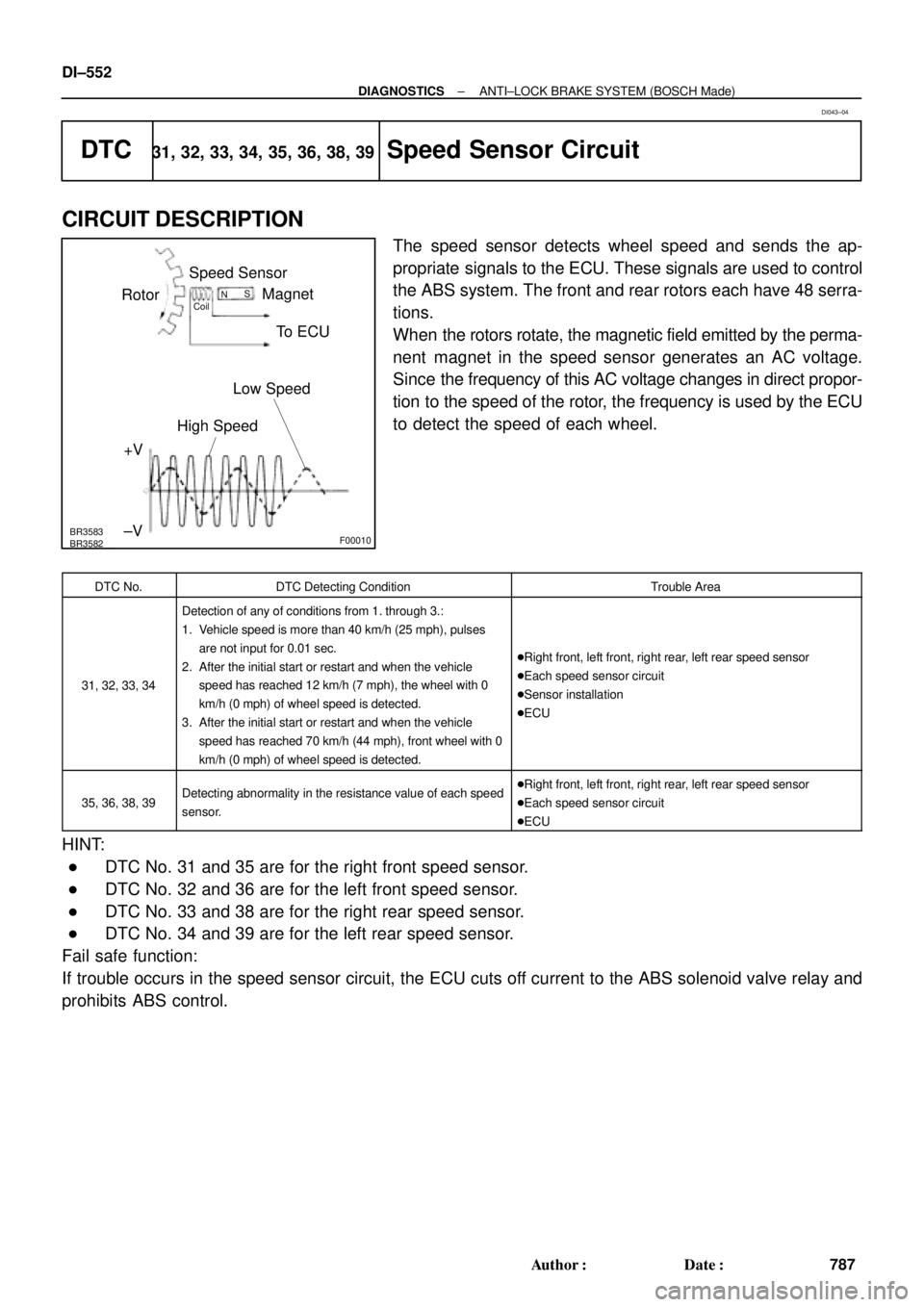
CIRCUIT DESCRIPTION
The speed sensor detects wheel speed and sends the ap-
propriate signals to the ECU. These signals are used to control
the ABS system. The front and rear rotors each have 48 serra-
tions.
When the rotors rotate, the magnetic field emitted by the perma-
nent magnet in the speed sensor generates an AC voltage.
Since the frequency of this AC voltage changes in direct propor-
tion to the speed of the rotor, the frequency is used by the ECU
to detect the speed of each wheel.
DTC No.DTC Detecting ConditionTrouble Area
31, 32, 33, 34
Detection of any of conditions from 1. through 3.:
1. Vehicle speed is more than 40 km/h (25 mph), pulses
are not input for 0.01 sec.
2. After the initial start or restart and when the vehicle
speed has reached 12 km/h (7 mph), the wheel with 0
km/h (0 mph) of wheel speed is detected.
3. After the initial start or restart and when the vehicle
speed has reached 70 km/h (44 mph), front wheel with 0
km/h (0 mph) of wheel speed is detected.
�Right front, left front, right rear, left rear speed sensor
�Each speed sensor circuit
�Sensor installation
�ECU
35, 36, 38, 39Detecting abnormality in the resistance value of each speed
sensor.�Right front, left front, right rear, left rear speed sensor
�Each speed sensor circuit
�ECU
HINT:
�DTC No. 31 and 35 are for the right front speed sensor.
�DTC No. 32 and 36 are for the left front speed sensor.
�DTC No. 33 and 38 are for the right rear speed sensor.
�DTC No. 34 and 39 are for the left rear speed sensor.
Fail safe function:
If trouble occurs in the speed sensor circuit, the ECU cuts off current to the ABS solenoid valve relay and
prohibits ABS control.
DI043±04