Page 1765 of 4592
F00086
Right Front
Speed Sensor
Left Front
Speed Sensor
Right Rear
Speed Sensor
Left Rear
Speed SensorECU
FR+
FR±
FL+
FL±
RR+
RR±
RL+
RL± A6
A6
A6
A6
A6
A6
A6
A65
4
7
6
3
1
9
8 W
B
R
G
P
L
Y
BRR
G
PP
L
L
Y
Y
BR
BR 2
1
2
1
1
2
1
2IK2
IL1IK3
ID1IK2
IL1 IK3
ID1IK3
IK3 22 1
6
1
3
93
9 6Right Front
Speed Sensor
Left Front
Speed Sensor
Right Rear
Speed Sensor
Left Rear
Speed SensorECU
FR+
FR±
FL+
FL±
RR+
RR±
RL+
RL± A6
A6
A6
A6
A6
A6
A6
A65
4
7
6
3
1
9
8 W
B
R
G
P
L
Y
BRR
G
PP
L
L
Y
Y
BR
BR 2
1
2
1
1
2
1
2IK2
IL1IK3
ID1IK2
IL1 IK3
ID1IK3
IK3 22 1
6
1
3
93
9 6
± DIAGNOSTICSANTI±LOCK BRAKE SYSTEM (BOSCH Made)
DI±553
788 Author�: Date�:
WIRING DIAGRAM
Page 1766 of 4592
R14205
1
2
R14213
12 12
12
12
12
1212
DI±554
± DIAGNOSTICSANTI±LOCK BRAKE SYSTEM (BOSCH Made)
789 Author�: Date�:
INSPECTION PROCEDURE
1 Check speed sensor.
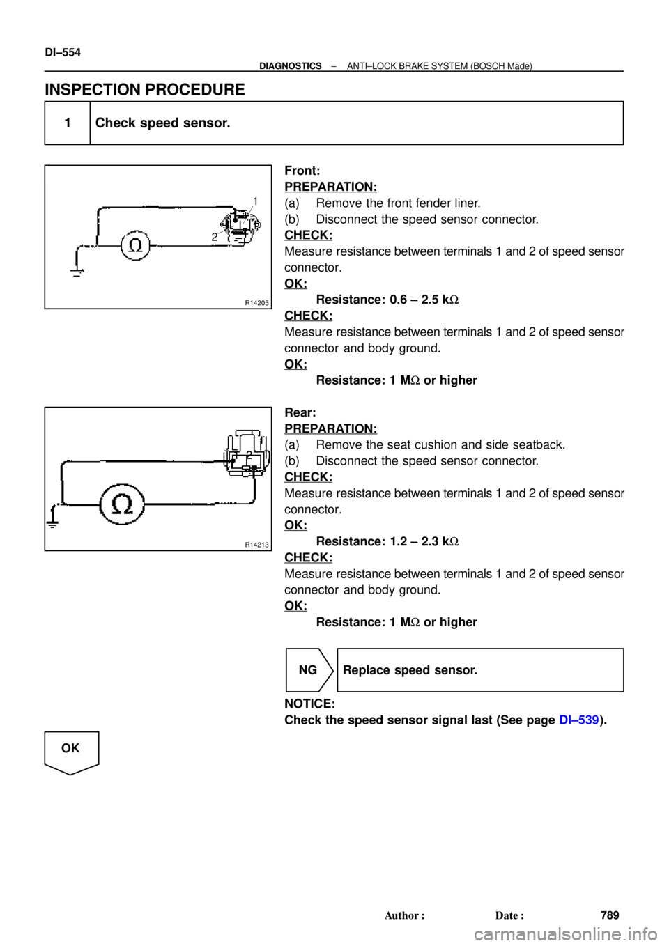
Front:
PREPARATION:
(a) Remove the front fender liner.
(b) Disconnect the speed sensor connector.
CHECK:
Measure resistance between terminals 1 and 2 of speed sensor
connector.
OK:
Resistance: 0.6 ± 2.5 kW
CHECK:
Measure resistance between terminals 1 and 2 of speed sensor
connector and body ground.
OK:
Resistance: 1 MW or higher
Rear:
PREPARATION:
(a) Remove the seat cushion and side seatback.
(b) Disconnect the speed sensor connector.
CHECK:
Measure resistance between terminals 1 and 2 of speed sensor
connector.
OK:
Resistance: 1.2 ± 2.3 kW
CHECK:
Measure resistance between terminals 1 and 2 of speed sensor
connector and body ground.
OK:
Resistance: 1 MW or higher
NG Replace speed sensor.
NOTICE:
Check the speed sensor signal last (See page DI±539).
OK
Page 1767 of 4592
BR3795
OK NG OK NG
OK NGOK NG
R00948
± DIAGNOSTICSANTI±LOCK BRAKE SYSTEM (BOSCH Made)
DI±555
790 Author�: Date�:
2 Check for open and short circuit in harness and connector between each speed
sensor and ECU (See page IN±31).
NG Repair or replace harness or connector.
OK
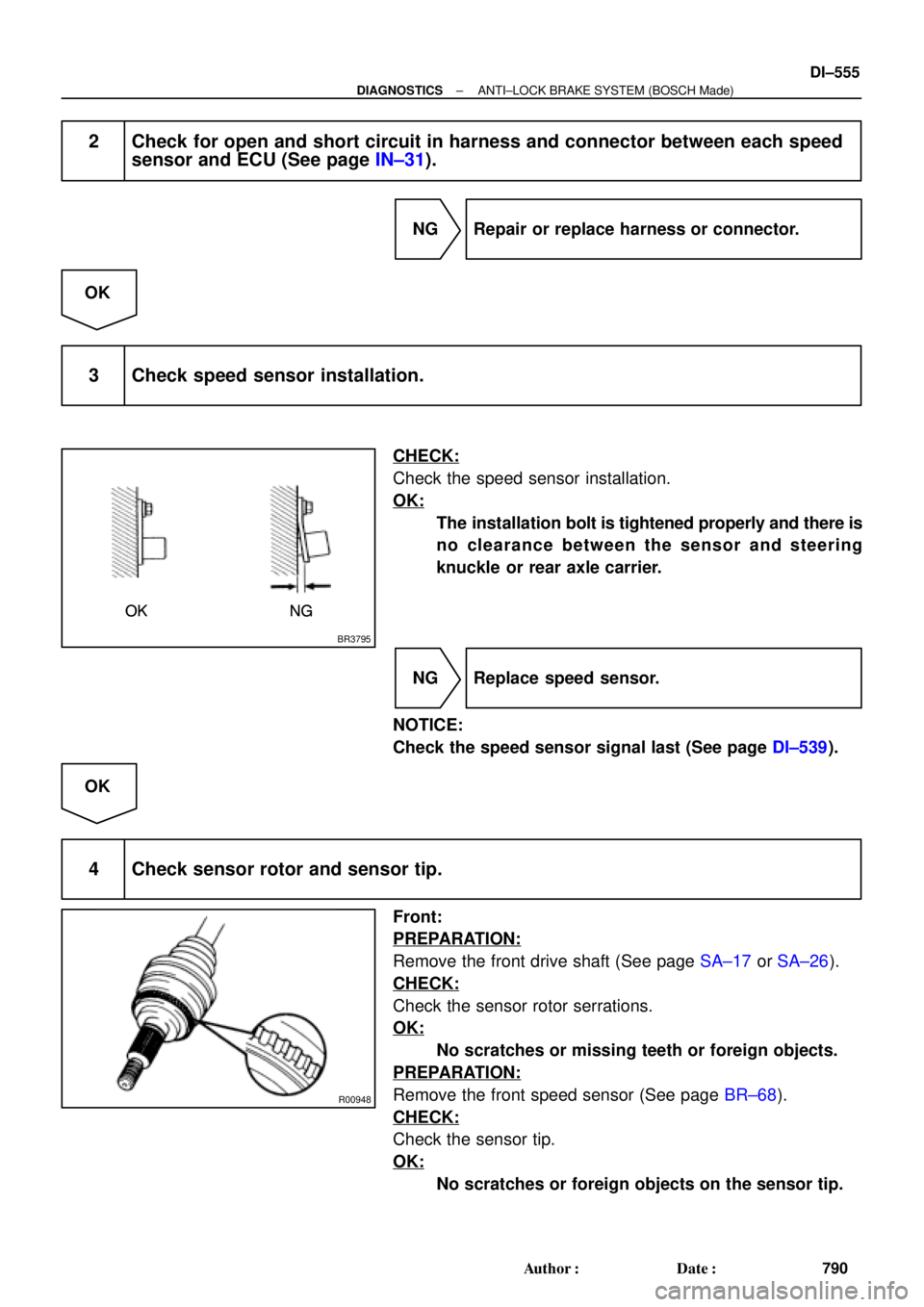
3 Check speed sensor installation.
CHECK:
Check the speed sensor installation.
OK:
The installation bolt is tightened properly and there is
no clearance between the sensor and steering
knuckle or rear axle carrier.
NG Replace speed sensor.
NOTICE:
Check the speed sensor signal last (See page DI±539).
OK
4 Check sensor rotor and sensor tip.
Front:
PREPARATION:
Remove the front drive shaft (See page SA±17 or SA±26).
CHECK:
Check the sensor rotor serrations.
OK:
No scratches or missing teeth or foreign objects.
PREPARATION:
Remove the front speed sensor (See page BR±68).
CHECK:
Check the sensor tip.
OK:
No scratches or foreign objects on the sensor tip.
Page 1768 of 4592
R00947
DI±556
± DIAGNOSTICSANTI±LOCK BRAKE SYSTEM (BOSCH Made)
791 Author�: Date�:
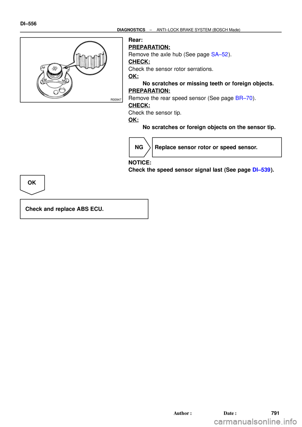
Rear:
PREPARATION:
Remove the axle hub (See page SA±52).
CHECK:
Check the sensor rotor serrations.
OK:
No scratches or missing teeth or foreign objects.
PREPARATION:
Remove the rear speed sensor (See page BR±70).
CHECK:
Check the sensor tip.
OK:
No scratches or foreign objects on the sensor tip.
NG Replace sensor rotor or speed sensor.
NOTICE:
Check the speed sensor signal last (See page DI±539).
OK
Check and replace ABS ECU.
Page 1769 of 4592

DI±557
792 Author�: Date�:
DTC 37 Speed Sensor Rotor Faulty
CIRCUIT DESCRIPTION
DTC No.DTC Detecting ConditionTrouble Area
37
Detection of any of co")
± DIAGNOSTICSANTI±LOCK BRAKE SYSTEM (BOSCH Made)
DI±557
792 Author�: Date�:
DTC 37 Speed Sensor Rotor Faulty
CIRCUIT DESCRIPTION
DTC No.DTC Detecting ConditionTrouble Area
37
Detection of any of conditions from 1. through 3.:
1. Occurrence of differential to some degree in the wheel
speed between the front and rear wheels of either left or
right side of the vehicle and the front left and right
wheels. (Detection of differential in mini tire size, spin-
ning wheel and decelerating wheel.)
2. Continuous ABS control for 60 sec. or more.
3. Interference on 1 or more wheels for 20 sec. with the
brake pedal depressed, or for 5 sec. when the brake
pedal is not depressed.
�Speed sensor
�Sensor rotor
�ECU
INSPECTION PROCEDURE
1 Check sensor rotor (See page DI±552).
NG Replace sensor rotor.
OK
2 Check speed sensor (See page DI±552).
NG Replace speed sensor.
OK
3 Check for open and short circuit in harness and connector between speed sen-
sor and ECU (See page IN±31).
NG Repair or replace harness and connector.
OK
Check and replace ABS ECU.
DI044±04
Page 1773 of 4592
F00125
MAIN
Battery ALT F4B±R
F91B
1C
STOP
B±G4
1 Instrument Panel J/B
FL Block
1 7 WA6
21S 5IK3 J28
G±WECU
J27
1RSTP
Stop Light SwitchJ/C
7
G±R
H10Light Failure
Sensor R
W±B A
R9 R11 C14
BP BL 11R
2
4
G±W G±W G±WG±W 1
Instrument
Panel J/B
2 1
G±RG±R
W±B W±B
W±B H10R9
R11
J/C
A A High
Mounted
Stop
LightRight
Stop
LightLeft
Stop
Light
J405 2
12
2
5
W±B
W±B
± DIAGNOSTICSANTI±LOCK BRAKE SYSTEM (BOSCH Made)
DI±561
796 Author�: Date�:
DTC 58 Stop Light Switch Circuit
CIRCUIT DESCRIPTION
DTC No.DTC Detecting ConditionTrouble Area
49
Stop light switch circuit is open, and stop light switch
voltage is in the level between 65 % or more and less
than 93 % of the battery voltage.�Stop light switch
�Stop light switch circuit
�ECU
WIRING DIAGRAM
INSPECTION PROCEDURE
1 Check operation of stop light.
CHECK:
Check that stop light lights up when brake pedal is depressed and turns off when brake pedal is released.
NG Repair stop light circuit (See page BE±36).
OK
DI046±09
Page 1781 of 4592
F00095
11ECU
R±Y
AA6 IK2
3
J/CDLC1
BR
Ts
J22: (1MZ±FE)16
EC5
E
1Ts
BRAII38
J23: (5S±FE)R±Y
11ECU
R±Y
AA6 IK2
3
J/CDLC1
BR
Ts
J22: (1MZ±FE)165
E
1Ts
BRAII38
J23: (5S±FE)R±Y B±Y (1MZ±FE)
LG (5S±FE)
AB0119S08096
F00446DLC1 DLC1
DLC1
DLC1
DLC1
Ts
DLC1 E1
ON
± DIAGNOSTICSANTI±LOCK BRAKE SYSTEM (BOSCH Made)
DI±569
804 Author�: Date�:
Ts Terminal Circuit
CIRCUIT DESCRIPTION
The sensor check circuit detects abnormalities in the speed sensor signal which cannot be detected with
the DTC check.
Connecting terminals Ts and E
1 of the DLC1 in the engine compartment starts the check.
WIRING DIAGRAM
INSPECTION PROCEDURE
1 Check voltage between terminals Ts and E1 of DLC1.
CHECK:
(a) Turn the ignition switch ON.
(b) Measure voltage between terminals Ts and E
1 of DLC1.
OK:
Voltage: 10 ± 14 V
OK If ABS warning light does not blink even after Ts
and E
1 are connected, the ECU may be defec-
tive.
NG
DI04A±08
Page 2086 of 4592

(2)
(1)
No.Operation MethodCRUISE MAIN Indicator Light
Blinking PatternDiagnosis
1 Turn SET/COAST switch ON
2Turn RES/ACC switch ON
3Turn CANCEL switch ON
Turn stop light switch ON
Depress")
N17520
(1)
(2)
(1)
No.Operation MethodCRUISE MAIN Indicator Light
Blinking PatternDiagnosis
1 Turn SET/COAST switch ON
2Turn RES/ACC switch ON
3Turn CANCEL switch ON
Turn stop light switch ON
Depress brake pedal
Turn PNP switch OFF
(Shift to except D position)
4Drive at about 40 km/h
(25 mph)or higher
Drive at about 40 km/h
(25 mph) or below
LightON
OFF
LightON
OFF
LightON
OFFSwitch ON
Switch OFF
LightON
OFFSwitch OFF
Switch ONSET/COAST switch circuit
is normal
RES/ACC switch circuit
is normal
CANCEL switch circuit
is normal
Stop light switch circuit
is normal
PNP switch circuit is
normal
Vehicle Speed Sensor is
normal
LightON
OFF LightON
OFF
1sec.
0.25 sec.0.25 sec.
Turn clutch switch OFF
(Depress clutch pedal)Clutch switch circuit
is normal
DI±874
± DIAGNOSTICSCRUISE CONTROL SYSTEM
1109 Author�: Date�:
5. INPUT SIGNAL CHECK
HINT:
(1) For check No.1 ~ No.3
�Turn ignition switch ON.
(2) For check No.4
�Jack up the vehicle.
�Start the engine.
�Shift to D position.
(a) Pull the control switch to SET/COAST or RES/ACC posi-
tion and hold it down or up (1).
(b) Push the main switch ON (2).
(c) Check that the CRUISE MAIN indicator light blinks twice
or 3 times repeatedly after 3 seconds.
(d) Turn the SET/COAST or RES/ACC switch OFF.
(e) Operate each switch as listed in the table below.
(f) Read the blinking pattern of the CRUISE MAIN indicator
light.
(g) After performing the check, turn the main switch OFF.
HINT:
When 2 or more signals are input to the ECU, the lowest num-
bered code will be displayed first.


16
EC5
E
1Ts
BRAII38
J23: (5S±FE)R±Y
11ECU
R±Y
AA6 IK2
3
J/CDLC1
BR
Ts
J22: (1MZ±FE)165
E
1Ts
BRAII38
J23: (5S±FE)R±Y B±Y (1MZ±FE)
LG (5")