1999 TOYOTA CAMRY brake sensor
[x] Cancel search: brake sensorPage 4455 of 4592
ABS AND TRACTION CONTROL
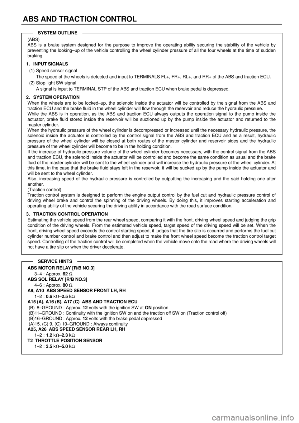
(ABS)
ABS is a brake system designed for the purpose to improve the operating ability securing the stability of the vehicle by
preventing the looking±up of the vehicle controlling the wheel cylinder pressure of all the four wheels at the time of sudden
braking.
1. INPUT SIGNALS
(1) Speed sensor signal
The speed of the wheels is detected and input to TERMINALS FL+, FR+, RL+, and RR+ of the ABS and traction ECU.
(2) Stop light SW signal
A signal is input to TERMINAL STP of the ABS and traction ECU when brake pedal is depressed.
2. SYSTEM OPERATION
When the wheels are to be locked±up, the solenoid inside the actuator will be controlled by the signal from the ABS and
traction ECU and the brake fluid in the wheel cylinder will flow through the reservoir and reduce the hydraulic pressure.
While the ABS is in operation, as the ABS and traction ECU always outputs the operation signal to the pump inside the
actuator, brake fluid stored inside the reservoir will be suctioned up by the pump inside the actuator and returned to the
master cylinder.
When the hydraulic pressure of the wheel cylinder is decompressed or increased until the necessary hydraulic pressure, the
solenoid inside the actuator is controlled by the control signal from the ABS and traction ECU and as a result, hydraulic
pressure of the wheel cylinder will be closed at both routes of the master cylinder and reservoir sides and the hydraulic
pressure of the wheel cylinder will become to be in the holding condition.
If the increase of hydraulic pressure volume of the wheel cylinder becomes necessary, with the control signal from the ABS
and traction ECU, the solenoid inside the actuator will be controlled and become the same condition as usual and the brake
fluid of the master cylinder will be sent to the wheel cylinder and will increase the hydraulic pressure of the wheel cylinder. At
this time, in the case that the brake fluid stays left in the reservoir, it will be sucked up by the pump inside the actuator and
will be sent to the wheel cylinder.
Also, increasing speed of the hydraulic pressure is controlled by outputting the increasing and the said holding one after
another.
(Traction control)
Traction control system is designed to perform the engine output control by the fuel cut and hydraulic pressure control of
driving wheel brake and control the spinning of the driving wheels. By doing this, it improves starting acceleration and
operating ability of the vehicle securing the driving ability in accordance with the road surface condition.
3. TRACTION CONTROL OPERATION
Estimating the vehicle speed from the rear wheel speed, comparing it with the front, driving wheel speed and judging the grip
condition of the driving wheels. From the estimated vehicle speed, target speed of the driving speed will be set. When the
front, driving wheel speed exceeds the control starting speed, it judges that the tire slip is occurred and performs the fuel cut
cylinder number control and brake control and then adjust to make the front wheel speed become the traction control target
speed. Controlling of the traction control will be completed when the vehicle move onto the road where the driving wheels will
not have a tire slip or when the driver decelerate.
ABS MOTOR RELAY [R/B NO.3]
3±4 : Approx. 62 W
ABS SOL RELAY [R/B NO.3]
4±6 : Approx. 80 W
A9, A10 ABS SPEED SENSOR FRONT LH, RH
1±2 :0.6 kW±2.5 kW
A15 (A), A16 (B), A17 (C) ABS AND TRACTION ECU
(B) 8±GROUND : Approx. 12 volts with the ignition SW at ON position
(B)11±GROUND : Continuity with the ignition SW on and the traction off SW on (Traction control off)
(B)16±GROUND : Approx. 12 volts with the brake pedal depressed
(A)15, (C) 9, (C) 10±GROUND : Always continuity
A25, A26
ABS SPEED SENSOR REAR LH, RH
1±2 :1.2 kW±2.3 kW
T2 THROTTLE POSITION SENSOR
1±2 :3.5 kW±5.0 kW
SYSTEM OUTLINE
SERVICE HINTS
Page 4461 of 4592
ABS (TMC MADE)
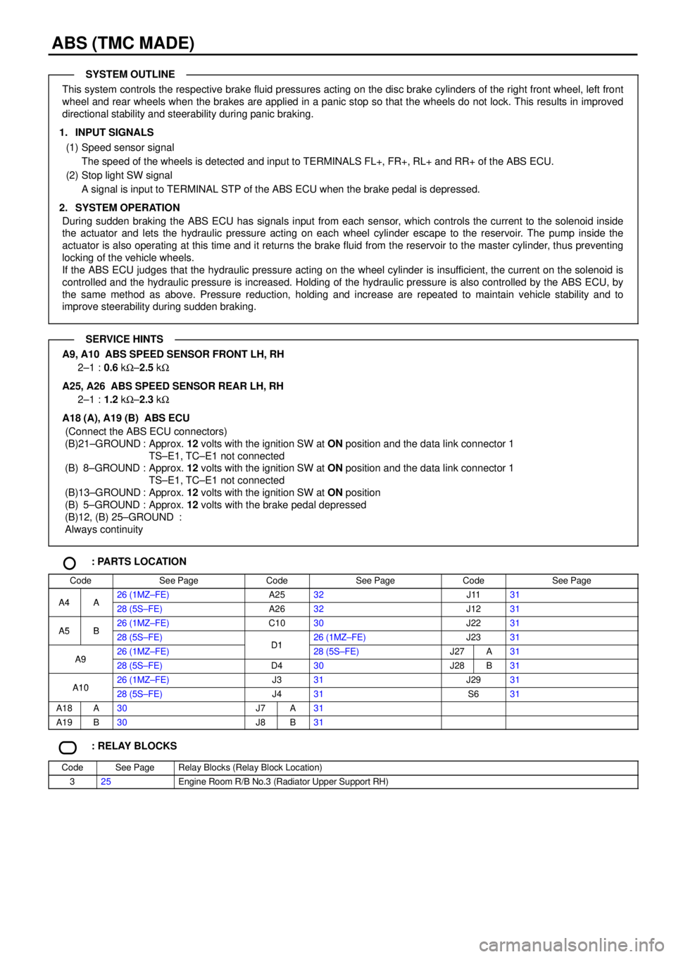
This system controls the respective brake fluid pressures acting on the disc brake cylinders of the right front wheel, left front
wheel and rear wheels when the brakes are applied in a panic stop so that the wheels do not lock. This results in improved
directional stability and steerability during panic braking.
1. INPUT SIGNALS
(1) Speed sensor signal
The speed of the wheels is detected and input to TERMINALS FL+, FR+, RL+ and RR+ of the ABS ECU.
(2) Stop light SW signal
A signal is input to TERMINAL STP of the ABS ECU when the brake pedal is depressed.
2. SYSTEM OPERATION
During sudden braking the ABS ECU has signals input from each sensor, which controls the current to the solenoid inside
the actuator and lets the hydraulic pressure acting on each wheel cylinder escape to the reservoir. The pump inside the
actuator is also operating at this time and it returns the brake fluid from the reservoir to the master cylinder, thus preventing
locking of the vehicle wheels.
If the ABS ECU judges that the hydraulic pressure acting on the wheel cylinder is insufficient, the current on the solenoid is
controlled and the hydraulic pressure is increased. Holding of the hydraulic pressure is also controlled by the ABS ECU, by
the same method as above. Pressure reduction, holding and increase are repeated to maintain vehicle stability and to
improve steerability during sudden braking.
A9, A10 ABS SPEED SENSOR FRONT LH, RH
2±1 :0.6 kW±2.5 kW
A25, A26 ABS SPEED SENSOR REAR LH, RH
2±1 :1.2 kW±2.3 kW
A18 (A), A19 (B) ABS ECU
(Connect the ABS ECU connectors)
(B)21±GROUND : Approx. 12 volts with the ignition SW at ON position and the data link connector 1
TS±E1, TC±E1 not connected
(B) 8±GROUND : Approx. 12 volts with the ignition SW at ON position and the data link connector 1
TS±E1, TC±E1 not connected
(B)13±GROUND : Approx. 12 volts with the ignition SW at ON position
(B) 5±GROUND : Approx. 12 volts with the brake pedal depressed
(B)12, (B) 25±GROUND :
Always continuity
: PARTS LOCATION
CodeSee PageCodeSee PageCodeSee Page
A4A26 (1MZ±FE)A2532J1131A4A28 (5S±FE)A2632J1231
A5B26 (1MZ±FE)C1030J2231A5B28 (5S±FE)D126 (1MZ±FE)J2331
A926 (1MZ±FE)D128 (5S±FE)J27A31A928 (5S±FE)D430J28B31
A1026 (1MZ±FE)J331J2931A1028 (5S±FE)J431S631
A18A30J7A31
A19B30J8B31
: RELAY BLOCKS
CodeSee PageRelay Blocks (Relay Block Location)
325Engine Room R/B No.3 (Radiator Upper Support RH)
SYSTEM OUTLINE
SERVICE HINTS
Page 4467 of 4592
ABS (TMMK MADE)
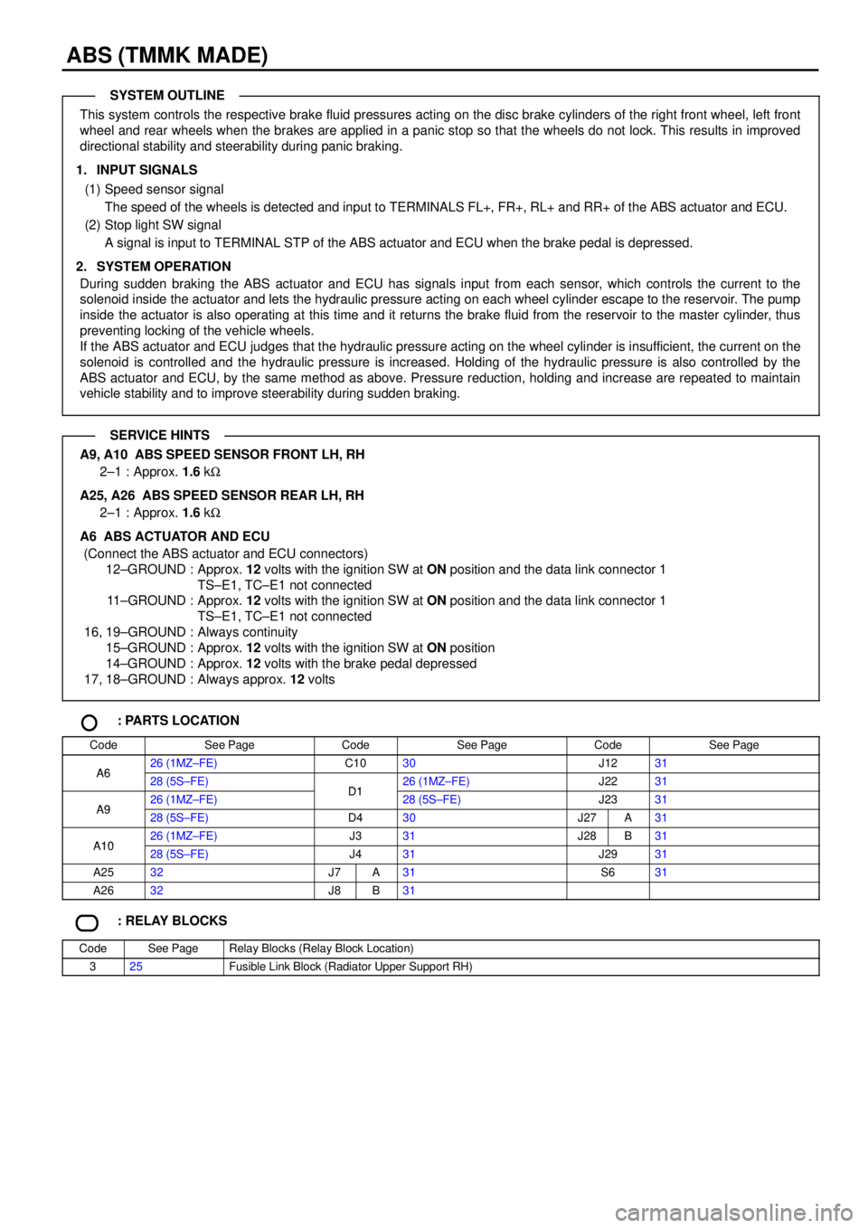
This system controls the respective brake fluid pressures acting on the disc brake cylinders of the right front wheel, left front
wheel and rear wheels when the brakes are applied in a panic stop so that the wheels do not lock. This results in improved
directional stability and steerability during panic braking.
1. INPUT SIGNALS
(1) Speed sensor signal
The speed of the wheels is detected and input to TERMINALS FL+, FR+, RL+ and RR+ of the ABS actuator and ECU.
(2) Stop light SW signal
A signal is input to TERMINAL STP of the ABS actuator and ECU when the brake pedal is depressed.
2. SYSTEM OPERATION
During sudden braking the ABS actuator and ECU has signals input from each sensor, which controls the current to the
solenoid inside the actuator and lets the hydraulic pressure acting on each wheel cylinder escape to the reservoir. The pump
inside the actuator is also operating at this time and it returns the brake fluid from the reservoir to the master cylinder, thus
preventing locking of the vehicle wheels.
If the ABS actuator and ECU judges that the hydraulic pressure acting on the wheel cylinder is insufficient, the current on the
solenoid is controlled and the hydraulic pressure is increased. Holding of the hydraulic pressure is also controlled by the
ABS actuator and ECU, by the same method as above. Pressure reduction, holding and increase are repeated to maintain
vehicle stability and to improve steerability during sudden braking.
A9, A10 ABS SPEED SENSOR FRONT LH, RH
2±1 : Approx. 1.6 kW
A25, A26 ABS SPEED SENSOR REAR LH, RH
2±1 : Approx. 1.6 kW
A6 ABS ACTUATOR AND ECU
(Connect the ABS actuator and ECU connectors)
12±GROUND : Approx. 12 volts with the ignition SW at ON position and the data link connector 1
TS±E1, TC±E1 not connected
11±GROUND : Approx. 12 volts with the ignition SW at ON position and the data link connector 1
TS±E1, TC±E1 not connected
16, 19±GROUND : Always continuity
15±GROUND : Approx. 12 volts with the ignition SW at ON position
14±GROUND : Approx. 12 volts with the brake pedal depressed
17, 18±GROUND : Always approx. 12 volts
: PARTS LOCATION
CodeSee PageCodeSee PageCodeSee Page
A626 (1MZ±FE)C1030J1231A628 (5S±FE)D126 (1MZ±FE)J2231
A926 (1MZ±FE)D128 (5S±FE)J2331A928 (5S±FE)D430J27A31
A1026 (1MZ±FE)J331J28B31A1028 (5S±FE)J431J2931
A2532J7A31S631
A2632J8B31
: RELAY BLOCKS
CodeSee PageRelay Blocks (Relay Block Location)
325Fusible Link Block (Radiator Upper Support RH)
SYSTEM OUTLINE
SERVICE HINTS
Page 4506 of 4592
5A
STARTER FROM POWER SOURCE SYSTEM (
SEE PAGE 50)
1J 3
IJ1 5IF2 5 IG2 5IG317 IG23
IK2 3 C 9B 2
B 5C10 A4C4C11 A3B7C3A5A12
EB 2 1 II2 11A B
B C
IG1 6
11
IG1 7
12 1
IG
R±Y
B±W
GR
B±O Y±B Y±B
O O
R±W
R±L
P±L
Y±G P±L P±L W±B
Y±G
R±W R±W R±W
R±W W±B
B±W
B±WB±W
B±O
R±W
R±W R±W
R±W PARK /NEUTRAL
POSITION SW P 1
OIL PRESSURE
SW O 1
PARKING
BRAKE SW P 3 CLUTCH START SW C 7
WASHER LEVEL
WARNING SW W 1
JUNCTION
CONNECTOR J 2
BRAKE FLUID
LEVEL WARNING SW B 2
JUNCTION
CONNECTOR J11L
LG
G± O
B5
B B6
2B B
BFROM THEFT
DETERRENT ECU SECURITY
OIL
CRUISE
SEAT BELT
ABS
WASHER LEVEL
REAR LIGHTS
BRAKE
BULB
CHECK
RELAY
TRAC OFF
SLIP
O/D OFF
(
A/T)
(
M/T) JUNCTION
CONNE CTOR J29
(
M/T) (
A/T)
P
N
(
*5)
(
*6) (
*3)
(
*4)
(
*4)PKB BRK
A
TO CRUISE
CONTROL ECU
TO INTEGRATION
RELAY
TO ABS ECU
TO ABS AND TRACTION ECU
TO ABS ACTUATOR AND ECU
TO LI GHT
FAI LURE
SENSORTO ABS AND
TRACTION
ECU
GR
(
A/T)
II2 10
GR
B±O
B±O(
*5 A/T)
(
*6 A/T)
TO O/D
MAIN SWJ 7
JUNCTION
CONNECTORB A, J 8
C 8
COMBINA TION METERB A, C 9 C, C10* 1 : 1 MZ± FE
* 2 : 5S±FE
* 3 : W/O DAYTIME RUNNING LIGHT
* 4 : W/ DAYTIME RUNNING LIGHT
* 5 : TMC MADE
* 6 : TMMK MADE
B 4(
*2) A 18(
*1)
A 8(
*1)
B 14(
*2)
B D 6 , A
DAY TIME RUNNING
LIGHT RELAY (
MAIN)
Page 4533 of 4592
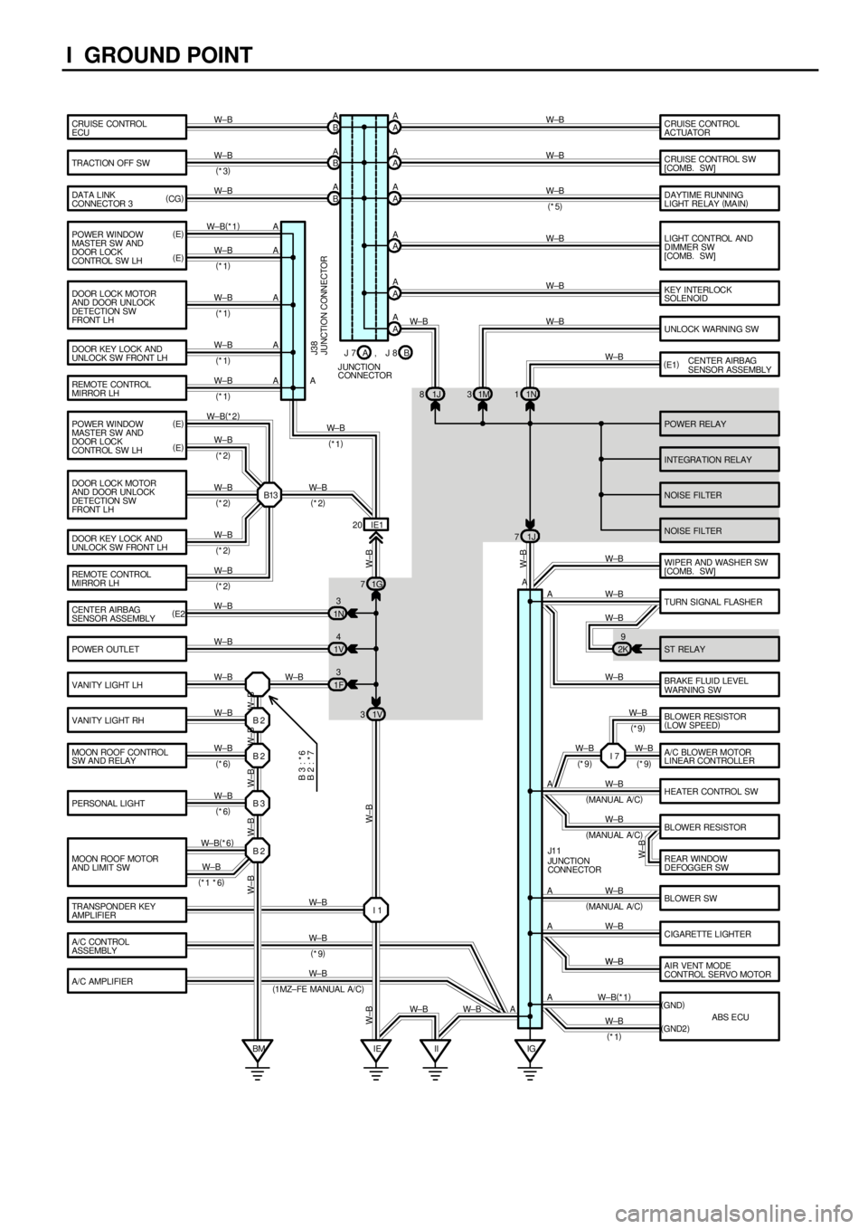
I GROUND POINT
CRUISE CONTROL
ECU
TRACTI ON OFF SW
DATA LINK
CONNECTOR 3
POWER RELAY
INTEGRA TION RELAY
NOISE FILTER POWER WINDOW
MASTER SW AND
DOOR LOCK
CONTROL SW LHCRUISE CONTROL
ACTUATOR
CRUISE CONTROL S W
[COMB. SW]
LIGHT CONTROL AND
DIMMER SW
[COMB. SW]
KEY INTERLOCK
SOLENOID
UNLOCK WARNING SW
CENTER AIRBAG
SENSOR ASSEMBLY
WIPER AND WASHER SW
[COMB. SW]
BRAKE FLUID LEVEL
WARNING SW
A/C AMPLIFIERHEATER CONTROL SW
AIR VENT MODE
CONTROL SERVO MOTOR BLOWER SW BLOWER RESISTOR
REAR WINDOW
DEFOGGER SW
CIGARETTE LIGHTER TURN SIGNAL FLASHE R
ST RELAY DOOR LOCK MOTOR
AND DOOR UNLOCK
DETECTION SW
FRONT L H
DOOR KEY LOCK AND
UNLOCK SW FRONT LH
REMOTE CONTROL
MIRROR LH
CENTER AIRB AG
SENSOR ASSEMBLY
POWER OUTLET
VANITY LIGHT LH
VANITY LIGHT RH
MOON ROOF CONTROL
SW AND RELAY
PERSONAL LIGHT
MOON ROOF MOTOR
AND LIMIT SWA A
A A
A A
A A
A A B A
B A
B A
1J 81M31N1
A A
A
A
A
A
A
A
A A A
1N3
1V4
1F31G 7
1V 3IE1 20
IG IE B 2
B 2
B 3
B 2
BM IIANOISE FILTER W±B
W±B
W±B
W±B W±B W±B W±B W±B W±B
W±B
W±B W±B
W±B W±B(
*2)
W±B
W±B
W±B
W±B
W±B
W±B
W±B W±B
W±B
W±B
W±B
W± B(
*6)
W± B W± B
W±B W± B W±B W± B
W± B
JUNCTION CONNECTOR J38
JUNCTION
CONNECTOR J1 1
W±BW±B
W± B (
*3)
B 3 : * 6
B 2 : * 7
(
E)
(
E) (
CG)
(
E1)
(
E2)
W±B
(
*1 *6)
W±B
DAYTIME RUNNING
LIGHT RELAY (
MAIN) A A
W±B
(
*5)
(
1 MZ± FE MANUAL A/ C)2K9
I 1 TRANSPONDER KEY
AMPLIFIERW± B
W±B
W±B
W±B W±B W±B W±B W±B 1J 7
W±B
W± B
W±B
J 7
J UNCTION
CONNECTORB A, J 8 POWER WINDOW
MASTER SW AND
DOOR LOCK
CONTROL SW LH
DOOR LOCK MOTOR
AND DOOR UNLOCK
DETECTION SW
FRONT L H
DOOR KEY LOCK AND
UNLOCK SW FRONT LH
REMOTE CONTROL
MIRROR LHW±B(
*1)
W±B
W±B
W±B
W±B (
E)
(
E)
B13 (
*1)
(
*1)
(
*1) (
*1)
(
*2)
(
*2)
(
*2)
(
*2)(
*1)
W± B
(
*2)
A/C CONTROL
ASSEMBLYW± B
(
*9) (
*6)
(
*6)(
MANU AL A/ C)
(
MANU AL A/ C)
(
MANU AL A/ C)BLOWER RESISTOR
(
LOW SPEED)
A/C BLOWER MOTOR
LINEAR CONTROLLER I 7 W±B W±BW± B
(
*9)(
*9) (
*9)
ABS ECU (
GND)
(
GND2) AW±B(
*1)
W±B
(
*1)
Page 4589 of 4592

L PART NUMBER OF CONNECTORS
Code Part Name Part NumberCodePart Name Part Number
Note : Not all of the above part numbers of the connector are established for the supply. In case of ordering
a connector or terminal with wire, please confirm in advance if there is supply for it using ªParts Catalog
Newsº (published by Parts Engineering Administration Dept.).
A 1A/C Condenser Fan Motor90980±10928
A 2A/C Magnetic Clutch and Lock Sensor90980±10942
A 3A/C Triple Pressure SW
(A/C Dual and Single Pressure SW)90980±10943
A 4ABS Actuator90980±11413
A 5ABS Actuator90980±10891
A 6ABS Actuator and ECU90080±98070
A 7ABS and Traction Actuator90980±11698
A 8ABS and Traction Actuator90980±11413
A 9ABS Speed Sensor Front LH90980±11075A10ABS Speed Sensor Front RH90980±11 075
A11Air Fuel Ratio Sensor90980±11178
A12A/C Amplifier90980±10807
A13A/C Evaporator Temp. Sensor90980±10825
A14A/C SW90980±10631
A15ABS and Traction ECU90980±11390
A16ABS and Traction ECU90980±11391
A17ABS and Traction ECU90980±11424A18ABS ECU90980±11424
A19ABS ECU90980±11390
A20Air Vent Mode Control Servo Motor90980±11165
A22Airbag Squib
(Front Passenger Airbag Assembly)90980±11884
A23Airbag Squib (Steering Wheel Pad)90980±10850
A24Ashtray Illumination81945±33010
A25ABS Speed Sensor Rear LH90980±11060A26ABS Speed Sensor Rear RH90980±11060
A27Auto Antenna Motor and Relay90980±11697
A28Air Fuel Ratio Sensor (Bank 1 Sensor 1)90980±11178A29Air Fuel Ratio Sensor (Bank 2 Sensor 1)90980±11 178
A30A/C Ambient Temp. Sensor90980±11070
A31Airbag Sensor Front LH90980±11856A32Airbag Sensor Front RH90980±11 856
A33A/C Blower Motor Linear Controller90980±11676
A34A/C Control Assembly90980±11390
A35A/C Control Assembly90980±11391
A36A/C Room Temp. Sensor90980±10825
A37A/C Solar Sensor90980±11918
A38Air Inlet Control Servo Motor90980±11165
A39Air Mix Control Servo Motor90980±11319
A40Automatic Light Control Sensor90980±11107
B 1Back±Up Light SW90980±11250
B 2Brake Fluid Level Warning SW90980±11207
B 3Blower Motor90980±10903
B 4Blower Resistor90980±10976
B 5Blower SW90980±10877
B 6Buckle SW LH90980±10825B 7Buckle SW LH90980±10825
B 8Blower Resistor (Low Speed)90980±10976
C 1Camshaft Position Sensor90980±10947C 2Crankshaft Position Sensor90980±10947
C 3Cruise Control Actuator90980±11150
C 4Cigarette Lighter90980±10760
C 5Cigarette Lighter Illumination90980±11148
C 6Clock90980±11013
C 7Clutch Start SW90980±10825
C8Combination Meter (TMC Made)90980±11114C 8Combination Meter (TMMK Made)90980±98048
C9Combination Meter (TMC Made)90980±11113C 9Combination Meter (TMMK Made)90980±98046
C10Combination Meter (TMC Made)90980±11115C10Combination Meter (TMMK Made)90980±98047
C11Combination SW90980±11594
C12Combination SW90980±11616
C13Combination SW90980±11672
C14Cruise Control Clutch SW90980±10906
C15Cruise Control ECU90980±11391
C16Condenser90980±10860
C17Center Airbag Sensor Assembly90980±11869
C18Center Airbag Sensor Assembly90980±11872
C19Center Airbag Sensor Assembly90980±11867
D1Data Link Connector 1 (1MZ±FE)90980±11195D 1Data Link Connector 1 (5S±FE)90980±11323
D 2Daytime Running Light Resistor90980±10928
D 3Diode (A/C)90980±11071
D 4Data Link Connector 290980±11417
D 5Data Link Connector 390980±11665
D6Daytime Running Light Relay (Main)90980±11058D 6Daytime Running Light Relay (Main)90980±11 058
D7Di d (C t )D7Diode (Courtesy)D 7Diode (Courtesy)90980±10962D10Diode (Dome)90980±10962
D11Diode (Idle±Up)90980±11071
D12Door Courtesy SW Front LH
D13Door Courtesy SW Front RH90980±10871D14Door Courtesy SW Rear LH90980±10871
D15Door Courtesy SW Rear RH
D16Door Key Lock and Unlock SW Front LH90980±11490D17Door Key Lock and Unlock SW Front RH90980±11490
Page 4591 of 4592

L PART NUMBER OF CONNECTORS
Code Part Name Part NumberCodePart Name Part Number
Note : Not all of the above part numbers of the connector are established for the supply. In case of ordering
a connector or terminal with wire, please confirm in advance if there is supply for it using ªParts Catalog
Newsº (published by Parts Engineering Administration Dept.).
J15Junction Connector90980±10803
J16Junction Connector90980±11661J17Junction Connector90980±11661
J18Junction Connector90980±11542J19Junction Connector90980±11542
J20Junction Connector90980±11539
J21Junction Connector90980±11542
J22Junction Connector90980±11539J23Junction Connector90980±11539
J24Junction Connector
J25Junction Connector90980±11529
J26Junction Connector
J27Junction Connector90980±11661J28Junction Connector90980±11661
J29Junction Connector90980±11502
J30Junction Connector90980±11661J31Junction Connector90980±11661
J32Junction Connector90980±10803
J33Junction Connector
J34Junction Connector90980±11661J35Junction Connector90980±11661
J36Junction Connector
J37Junction Connector90980±11542
J38Junction Connector90980±10803J39Junction Connector90980±10803
J40Junction Connector90980±10976
K 1Knock Sensor 190980±11166K 2Knock Sensor 290980±11166
K 3Key Interlock Solenoid90980±10825
L 1License Plate Light LH90980±11148L 2License Plate Light RH90980±11148
L 3Light Failure Sensor90980±10803
L 4Luggage Compartment Key Unlock SW90980±11212
L 5Luggage Compartment Light90980±11148
L 6Luggage Compartment Light SW90980±11097
M 1Manifold Absolute Pressure Sensor90980±10845
M 2Mass Air Flow Meter90980±11317
M 3Moon Roof Control SW and Relay90980±10799
M 4Moon Roof Motor and Limit SW90980±11011
N 1Noise Filter (Ignition)90980±10843
N 2Noise Filter (Rear Window Defogger)90980±11259
O 1Oil Pressure SW90980±11363
O 2O/D Main SW and A/T Shift Lever
Illumination90980±10795
P 1Park/Neutral Position SW,A/T Indicator Light
SW and Back±Up Light SW90980±11332
P 2Power Steering Oil Pressure SW90980±11428
P 3Parking Brake SW90980±10871
P 4Power Outlet90980±10760
P 5Personal Light90980±10825
P 6Power Window Control SW Front RH90980±10789
P 7Power Window Control SW Rear LH90980±10631P 8Power Window Control SW Rear RH90980±10631
P 9Power Window Master SW and Door Lock
Control SW LH90980±10807
P10Power Window Motor Front LH
P11Power Window Motor Front RH90980±10860P12Power Window Motor Rear LH90980±10860
P13Power Window Motor Rear RH
P14Power Seat Control SW (Driver's Seat)
P15Power Seat Control SW
(Front Passenger's Seat)90980±10803
P16Power Seat Motor
(Driver's Seat Rear Vertical Control)
P17Power Seat Motor
(Driver's Seat Reclining Control)90980±10825
P18Power Seat Motor
(Driver's Seat Slide Control)
P19Power Seat Motors (Driver's Seat)90980±11001
P20Power Seat Motor (Front Passenger's Seat
Rear Vertical Control)
P21Power Seat Motor (Front Passenger's Seat
Reclining Control)90980±10825
P22Power Seat Motor (Front Passenger's Seat
Slide Control)
P23Power Seat Motors
(Front Passenger's Seat)90980±11001
P24Pretensioner LH90980±11862P25Pretensioner RH90980±11862
R 1Radiator Fan Motor90980±10928
R 2Radio and Player90980±10996
R 3Radio and Player90980±10997
R 4Radio and Player90980±11264
R 5Rear Window Defogger SW90980±11280
R 6Remote Control Mirror SW90980±11450
R 7Rheostat90980±10908
R 8Rear Combination Light LH90980±10795
R 9Rear Combination Light LH90980±11001
R10Rear Combination Light RH90980±10795
R11Rear Combination Light RH90980±11001