Page 3634 of 4592

SA1JR±01
FA1535
SST
W03093
W03094
SST
W03095
SA±6
± SUSPENSION AND AXLEFRONT DRIVE SHAFT
REMOVAL
NOTICE:
�The hub bearing could be damaged if it is subjected
to the vehicle weight, such as when moving the ve-
hicle with the drive shaft removed.
Therefore, if it is absolutely necessary to place the ve-
hicle weight on the hub bearing, first support it with
SST.
SST 09608±16042 (09608±02021, 09608±02041)
�After disconnecting the drive shaft from the axle hub,
work carefully so as not to damage the ABS speed
sensor rotor serration on the drive shaft.
1. REMOVE FRONT WHEEL AND FRONT FENDER
APRON SEAL
2. DRAIN ATF
3. REMOVE DRIVE SHAFT LOCK NUT
(a) Remove the cotter pin and lock cap.
(b) While applying the brakes, remove the nut.
4. DISCONNECT TIE ROD END FROM STEERING
KNUCKLE
(a) Remove the cotter pin and nut.
(b) Using SST, disconnect the tie rod end from the steering
knuckle.
SST 09610±20012
5. DISCONNECT LOWER SUSPENSION ARM FROM
LOWER BALL JOINT
Remove the bolt and 2 nuts, and disconnect the lower suspen-
sion arm from the lower ball joint.
Page 3642 of 4592
 Install a new snap ring to the inboard joint shaft.
(b) Coat the gear oil")
SA1EC±02
SA±14
± SUSPENSION AND AXLEFRONT DRIVE SHAFT
INSTALLATION
1. LH drive shaft:
INSTALL DRIVE SHAFT TO TRANSAXLE
(a) Install a new snap ring to the inboard joint shaft.
(b) Coat the gear oil to the inboard joint shaft and differential case sliding surface.
(c) Set the snap ring with opening side facing downward.
(d) Using a brass bar and hammer, install the drive shaft.
NOTICE:
Be careful not to damage the dust cover of the drive shaft and oil seal lip of the transaxle.
HINT:
Whether the inboard joint shaft is in contact with the pinion shaft or not can be known from the sound or feel-
ing when driving it in.
(e) Check that there is 2 ± 3 mm (0.08 ± 0.12 in.) of play in the axial direction.
(f) Check that the drive shaft cannot be removed by hand.
2. RH drive shaft:
INSTALL DRIVE SHAFT TO TRANSAXLE
(a) Install the drive shaft.
NOTICE:
Be careful not to damage the dust cover of the drive shaft and oil seal lip of the transaxle.
(b) Using pliers, install a new snap ring.
(c) Install a new bearing lock bolt.
Torque: 32 N´m (330 kgf´cm, 24 ft´lbf)
3. CONNECT DRIVE SHAFT TO AXLE HUB
NOTICE:
Be careful not to damage the boot and ABS speed sensor rotor.
4. CONNECT LOWER SUSPENSION ARM TO LOWER BALL JOINT
Torque: 127 N´m (1,300 kgf´cm, 94 ft´lbf)
5. CONNECT TIE ROD END TO STEERING KNUCKLE
(a) Connect the tie rod end to the steering knuckle.
(b) Install the nut and a new cotter pin.
If the holes for the cotter pin are not aligned, tighten the nut further up to 60°.
Torque: 49 N´m (500 kgf´cm, 36 ft´lbf)
6. INSTALL DRIVE SHAFT LOCK NUT
(a) While applying brakes, install the nut.
Torque: 294 N´m (3,000 kgf´cm, 217 ft´lbf)
(b) Install the lock cap and a new cotter pin.
If the holes for the cotter pin are not aligned, tighten the nut further up to 60°.
7. FILL AND CHECK ATF (See page DI±133)
8. INSTALL FRONT FENDER APRON SEAL
9. INSTALL FRONT WHEEL
Torque: 103 N´m (1,050 kgf´cm, 76 ft´lbf)
10. CHECK FRONT WHEEL ALIGNMENT (See page SA±1)
11. CHECK ABS SPEED SENSOR SIGNAL (See page DI±177)
Page 3643 of 4592
SA07X±06
F08043
Suspension Support
Spring Bumper
Link Stabilizer Bar
Shock
Absorber
ABS Speed Sensor
Wire Harness ClampFront Drive Shaft with Coil SpringUpper SeatBearing
Lower
Insulator
Lower Suspension Arm Lower Suspension
Bushing StopperBrake CaliperInsulator UpperSpring Support No. 2Suspension
Shock Absorber
Coil Spring
Tie Rod End
� Dust
Deflector
� Cotter Pin
� Cotter Pin� Cotter
Pin
Lower Ball jointDisc
Lock Cap ABS Speed Sensor
N´m (kgf´cm, ft´lbf): Specified torque
� Non±reusable part�
80 (820, 59)49 (500, 36)
39 (400, 29)
211 (2,150, 156)
107 (1,090, 79)
29 (300, 22)
123 (1,250, 90)49 (500, 36)
8.0 (82, 71 in.´lbf)
294 (3,000, 217)
206 (2,100, 152)
206 (2,100, 152)
206 (2,100, 152)
127 (1,300, 94)
127 (1,300, 94)
± SUSPENSION AND AXLEFRONT LOWER BALL JOINT
SA±15
522 Author�: Date�:
FRONT LOWER BALL JOINT
COMPONENTS
Page 3644 of 4592
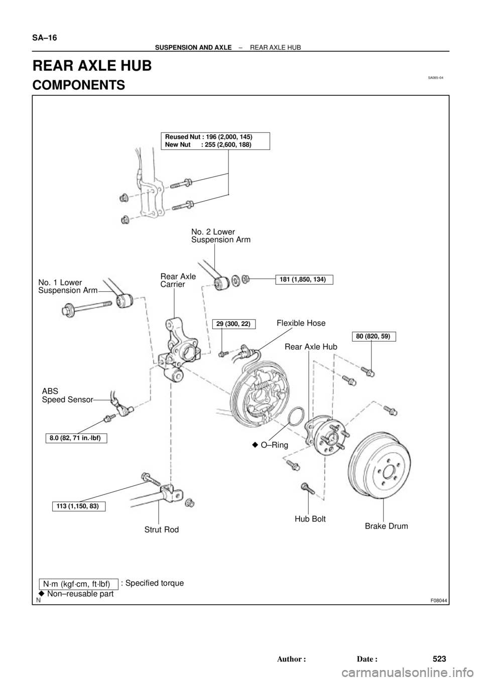
SA085±04
F08044
Flexible Hose
Rear Axle Hub
� O±Ring
Hub Bolt
Brake Drum No. 2 Lower
Suspension Arm
Rear Axle
Carrier No. 1 Lower
Suspension Arm
ABS
Speed Sensor
Strut Rod
N´m (kgf´cm, ft´lbf)
� Non±reusable part: Specified torque
Reused Nut : 196 (2,000, 145)
New Nut : 255 (2,600, 188)
8.0 (82, 71 in.´lbf)
113 (1,150, 83)
29 (300, 22)
80 (820, 59)
181 (1,850, 134)
SA±16
± SUSPENSION AND AXLEREAR AXLE HUB
523 Author�: Date�:
REAR AXLE HUB
COMPONENTS
Page 3939 of 4592
REAR BEARING O±RING SERVICE TIP ± SU001-02March 1, 2002
Page 2 of 2
4. Remove Rear Axle Hub.
A. Remove the 4 bolts and rear
axle hub.
Torque: 80 N�m (820 kgf�cm, 59 ft�lbf)
B. Remove the O±ring.
HINT:
At the time of installation, coat the new
O±ring with MP grease.
NOTE:
Please ensure that the O±ring is
replaced with a new service part when
installing the bearing assembly.
C. With Drum Brake:
Remove the bolt, and disconnect
the flexible hose from the shock
absorber.
Torque: 29 N�m (300 kgf�cm, 22 ft�lbf)
D. Support the backing plate
securely.
5. With ABS:
Remove ABS Speed Sensor.
Torque: 8.0 N�m (82 kgf�cm, 71 in�lbf)
INSTALLATION
Installation is in the reverse order of
removal.
Bolt
BoltBolt
Bolt
Page 3958 of 4592
 ± SS002-03December 17, 2003
Page 2 of 43
1. Clear any stored Diagnostic Trouble Codes (DTCs) using the Toyota
Diagnostic Tester.
2. Start the engine.
3. Perform the drive")
O2S TEST RESULTS (MODE 05) ± SS002-03December 17, 2003
Page 2 of 43
1. Clear any stored Diagnostic Trouble Codes (DTCs) using the Toyota
Diagnostic Tester.
2. Start the engine.
3. Perform the drive pattern below to run and complete the Oxygen Sensor (O2S) Monitor.
O2S Monitor Drive Pattern
ECT: 167�F (75�C) or more
Vehicle Speed
At Least 8 Times
48 km/h (30 mph)
IdlingAt Least Twice Accelerator Pedal
DepressingAccelerator Pedal
Releasing (Fuel±Cut)
6 mph
(10 km/h)
Time2 min.
or more40 sec
or more20 sec
or more10 sec
or more10 sec
or more
HINT:
The O2S Monitor is completed when the following conditions are met:
�Two (2) minutes or more passed after the engine start.
�The Engine Coolant Temperature (ECT) is 167�F (75�C) or more.
�Cumulative running time at 30 mph (48 km/h) or more exceeds 6 minutes.
�Vehicle is in closed loop.
�The fuel±cut is operated for 8 seconds or more (for Rear O2S Monitor).
A. Allow the engine to idle for two minutes.
B. Warm up the engine until the Engine Coolant Temperature (ECT) reaches 167�F
(75�C).
C. Drive the vehicle over 30 mph (48 km/h) for more than 40 seconds.
D. Stop the vehicle and allow the engine to idle for more than 20 seconds.
E. Repeat steps C and D at least 8 times in one driving cycle.
(Do not cycle the ignition key.)
In addition, perform the following steps for the Rear O2S Readiness Monitor:
A. Select second gear.
B. Allow the vehicle to run at 30 mph (48 km/h) or more.
C. Keep the accelerator pedal ªoff±idleº for more than 10 seconds.
D. Immediately after step C, release the accelerator pedal for at least 10 seconds
without depressing the brake pedal (to execute the fuel±cut).
E. Decelerate the vehicle until the vehicle speed reaches less than 6 mph (10 km/h).
F. Repeat steps B ± E at least twice in one driving cycle.
Completing
O2S
Readiness
Monitor
Page 4015 of 4592
![TOYOTA CAMRY 1999 Service Repair Manual [O]
[P]
[Q]
[R]
[S]
[T]
[U]
[V]
B HOW TO USE THIS MANUAL
Current is applied at all times through the STOP fuse to TERMINAL 2 of the stop light SW.
When the ignition SW is turned on, current flows fro](/manual-img/14/57448/w960_57448-4014.png "TOYOTA CAMRY 1999 Service Repair Manual [O]
[P]
[Q]
[R]
[S]
[T]
[U]
[V]
B HOW TO USE THIS MANUAL
Current is applied at all times through the STOP fuse to TERMINAL 2 of the stop light SW.
When the ignition SW is turned on, current flows fro")
[O]
[P]
[Q]
[R]
[S]
[T]
[U]
[V]
B HOW TO USE THIS MANUAL
Current is applied at all times through the STOP fuse to TERMINAL 2 of the stop light SW.
When the ignition SW is turned on, current flows from the GAUGE fuse to TERMINAL 8 of the light failure sensor, and also flows
through the rear lights warning light to TERMINAL 4 of the light failure sensor.
STOP LIGHT DISCONNECTION WARNING
When the ignition SW is turned on and the brake pedal is pressed (Stop light SW on), if the stop light circuit is open, the current
flowing from TERMINAL 7 of the light failure sensor to TERMINALS 1, 2 changes, so the light failure sensor detects the
disconnection and the warning circuit of the light failure sensor is activated.
As a result, the current flows from TERMINAL 4 of the light failure sensor to TERMINAL 11 to GROUND and turns the rear lights
warning light on. By pressing the brake pedal, the current flowing to TERMINAL 8 of the light failure sensor keeps the warning
circuit on and holds the warning light on until the ignition SW is turned off.
S6 STOP LIGHT SW
2±1 : Closed with the brake pedal depressed
L4 LIGHT FAILURE SENSOR
1, 2, 7±GROUND : Approx. 12 volts with the stop light SW on
4, 8±GROUND : Approx. 12 volts with the ignition SW at ON position
11±GROUND : Always continuity
: PARTS LOCATION
CodeSee PageCodeSee PageCodeSee Page
C734L436R737
H1736R637S635
: RELAY BLOCKS
CodeSee PageRelay Blocks (Relay Block Location)
118R/B No.1 (Instrument Panel Left)
��� ��� ���
@@@ @@@ @@@
€€€ €€€ €€€
ÀÀÀ ÀÀÀ ÀÀÀ
��� ��� ���: JUNCTION BLOCK AND WIRE HARNESS CONNECTOR
CodeSee PageJunction Block and Wire Harness (Connector Location)
IB20Instrument Panel Wire and Instrument Panel J/B (Lower Finish Panel)
3C22Instrument Panel Wire and J/B No.3 (Instrument Panel Left Side)
: CONNECTOR JOINING WIRE HARNESS AND WIRE HARNESS
CodeSee PageJoining Wire Harness and Wire Harness (Connector Location)
IE142Floor Wire and Instrument Panel Wire (Left Kick Panel)
BV150Luggage Room Wire and Floor Wire (Luggage Compartment Left)
: GROUND POINTS
CodeSee PageGround Points Location
BL50Under the Left Quarter Pillar
BO50Back Panel Center
: SPLICE POINTS
CodeSee PageWire Harness with Splice PointsCodeSee PageWire Harness with Splice Points
I544Cowl WireB1850Luggage Room Wire
SYSTEM OUTLINE
SERVICE HINTS
Page 4037 of 4592

A")
G ELECTRICAL WIRING ROUTING
Position of Parts in Engine Compartment
A 1 A/C Condenser Fan Motor
A 2 A/C Magnetic Clutch and Lock Sensor
A 3 A/C Triple Pressure SW
(A/C Dual and Single Pressure SW)
A 4 ABS Actuator
A 5 ABS Actuator
A 6 ABS Speed Sensor Front LH
A 7 ABS Speed Sensor Front RH
A 8 Air Fuel Ratio Sensor
A 9 Airbag Sensor Front LH
A 10 Airbag Sensor Front RH
B 1 Brake Fluid Level Warning SW
C 1 Camshaft Position Sensor
C 2 Crankshaft Position Sensor
C 3 Cruise Control Actuator
D 1 Data Link Connector 1
E 1 Electronically Controlled Transmission Solenoid
E 2 Electronically Controlled Transmission Solenoid
E 3 Engine Coolant Temp. SensorF 1 Front Turn Signal Light and Parking Light LH
F 2 Front Turn Signal Light and Parking Light RH
F 3 Front Wiper Motor
F 4 Fuel Pressure Sensor (Delivery Pipe)
F 5 Fuel Pressure Sensor (Fuel Pipe)
F 6 Fuel Shutoff Valve (Delivery Pipe)
F 7 Fuel Shutoff Valve (Fuel Pressure Regulator)
F 8 Fuel Temp. Sensor (Delivery Pipe)
F 9 Fusible Link Block
F 10 Fusible Link Block
F 11 Fusible Link Block
F 12 Fusible Link Block
F 13 Fusible Link Block
F 14 Fusible Link Block
G 1 Generator
G 2 Generator
H 1 Headlight LH
H 2 Headlight RH
H 3 Horn (High)
H 4 Horn (Low)


B. Remove the O±ring.
H")