Page 2533 of 4592
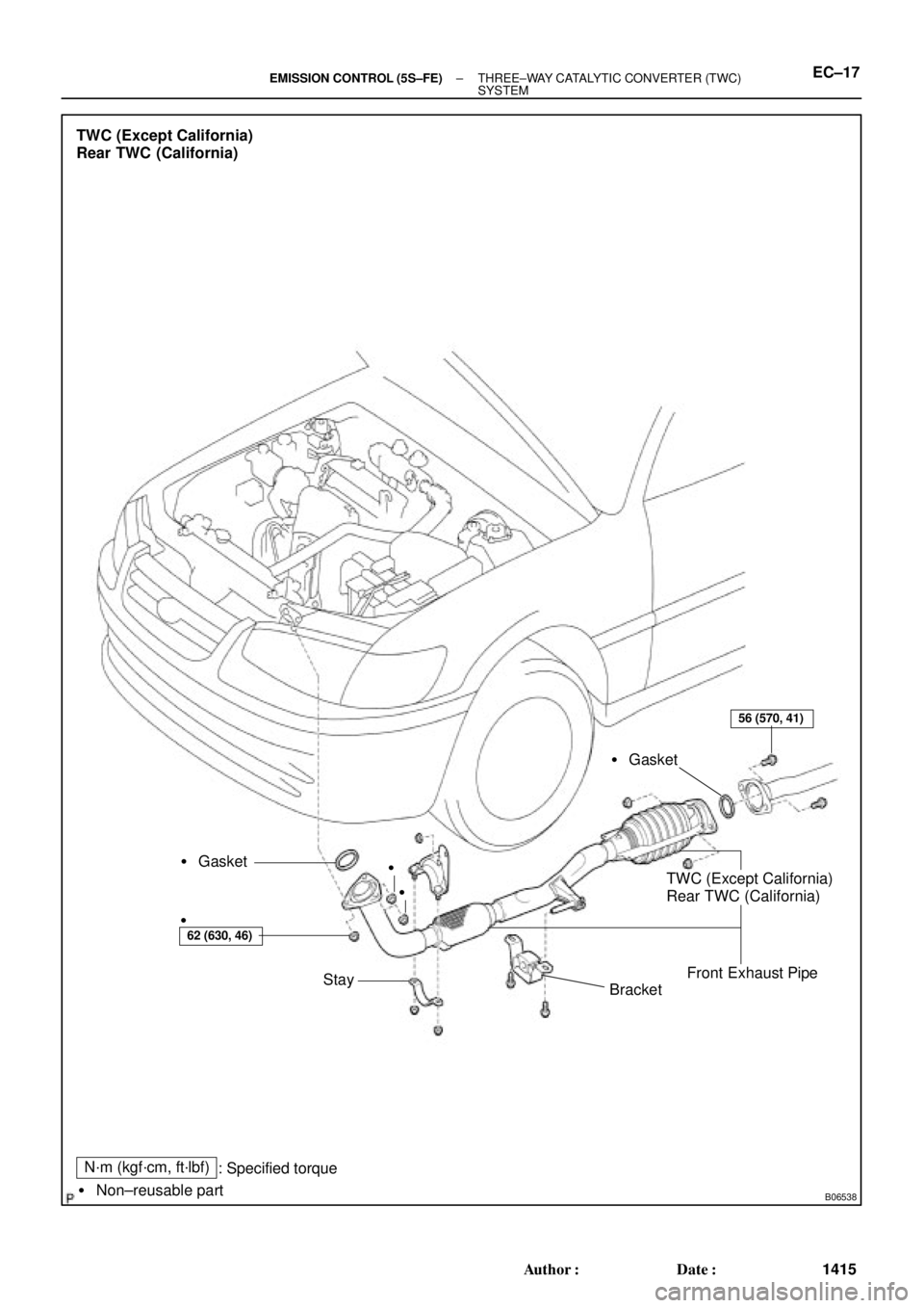
B06538
N´m (kgf´cm, ft´lbf)
� Non±reusable part
TWC (Except California)
Rear TWC (California)
� Gasket
BracketTWC (Except California)
Rear TWC (California)
Front Exhaust Pipe � Gasket
Stay
62 (630, 46)
56 (570, 41)
: Specified torque�
�
�
± EMISSION CONTROL (5S±FE)THREE±WAY CATALYTIC CONVERTER (TWC)
SYSTEMEC±17
1415 Author�: Date�:
Page 2534 of 4592
EC01U±03
± EMISSION CONTROL (1MZ±FE)EMISSION CONTROL SYSTEM
EC±1
1416 Author�: Date�:
EMISSION CONTROL SYSTEM
PURPOSE
The emission control systems are installed to reduce the amount of CO, HC and NOx exhausted from the
engine ((3), (4), (5) and (6)), to prevent the atmospheric release of blow±by gas±containing HC (1) and evap-
orated fuel containing HC being released from the fuel tank (2).
The function of each system is shown in these table.
SystemAbbreviationFunction
(1) Positive Crankcase Ventilation
(2) Evaporative Emission Control
(3) Exhaust Gas Recirculation
(4) Warm Up Three±Way Catalytic Converter
(5) Three±Way Catalytic Converter
(6) Sequential Multiport Fuel Injection*PCV
EVAP
EGR
WU±TWC
TWC
SFIReduces HC
Reduces evaporated HC
Reduces NOx
Reduces HC, CO and NOx
Reduces HC, CO and NOx
Injects a precisely timed, optimum amount of fuel for reduced
exhaust emissions
Remark: * For inspection and repair of the SFI system, refer to the SF section of this manual.
Page 2547 of 4592
EC020±04
EC±14± EMISSION CONTROL (1MZ±FE)WARM UP THREE±WAY CATALYTIC CONVERTER
(WU±TWC) SYSTEM (California A/T)
1429 Author�: Date�:
WARM UP THREE±WAY CATALYTIC CONVERTER
(WU±TWC) SYSTEM (California A/T)
ON±VEHICLE INSPECTION
1. INSPECT EXHAUST PIPE ASSEMBLY
(a) Check the connections for looseness or damage.
(b) Check the clamps for weakness, cracks or damage.
2. INSPECT WU±TWC
Check for dents or damage.
If any part of the protector is damaged or dented to the extent that it contacts the WU±TWC, repair or replace
it.
3. INSPECT WU±TWC HEAT INSULATOR
(a) Check the heat insulator for damage.
(b) Check for adequate clearance between the catalytic converter and heat insulator.
Page 2548 of 4592
EC021±04
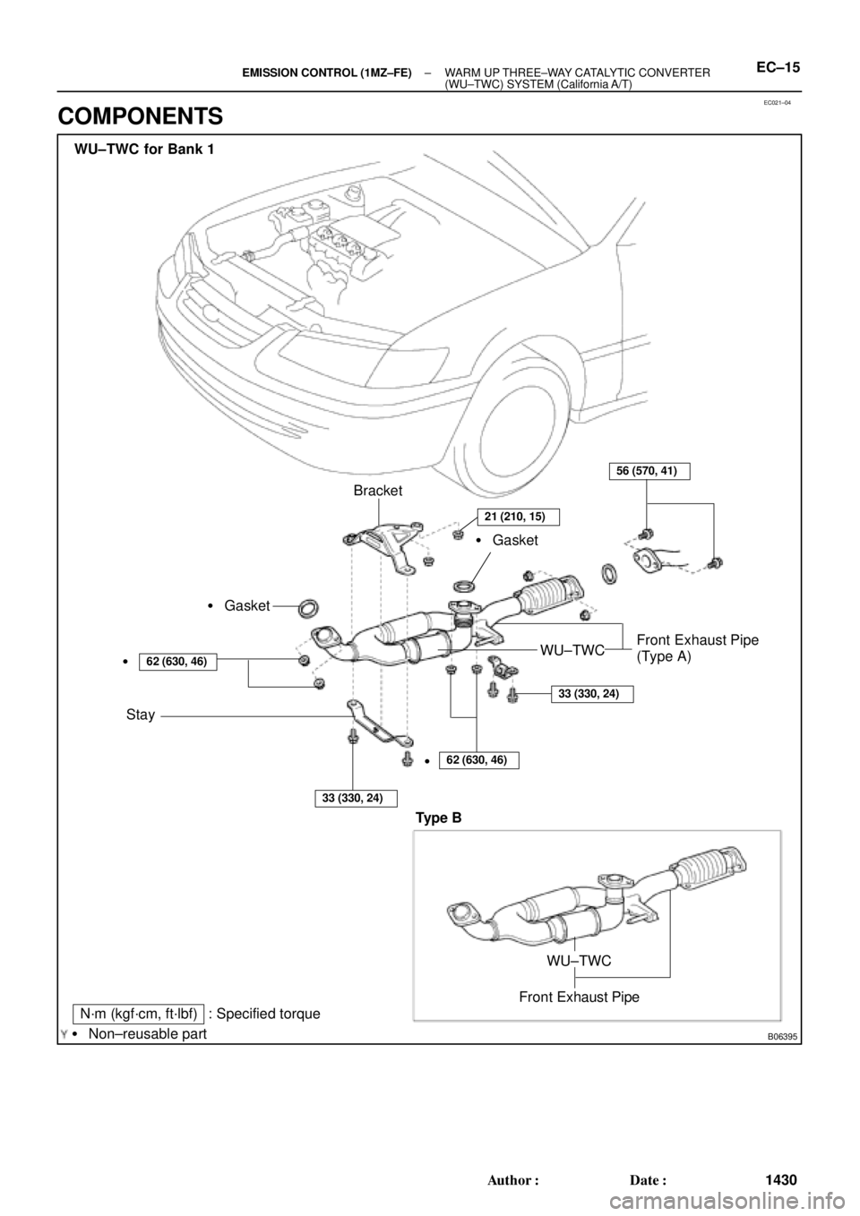
B06395
N´m (kgf´cm, ft´lbf) : Specified torque
� Non±reusable partBracket
� Gasket
Stay
62 (630, 46)
33 (330, 24)
56 (570, 41)
WU±TWCFront Exhaust Pipe
(Type A) � Gasket
�
62 (630, 46)
33 (330, 24)
WU±TWC for Bank 1
�
21 (210, 15)
Front Exhaust Pipe
WU±TWC
Type B
± EMISSION CONTROL (1MZ±FE)WARM UP THREE±WAY CATALYTIC CONVERTER
(WU±TWC) SYSTEM (California A/T)EC±15
1430 Author�: Date�:
COMPONENTS
Page 2549 of 4592
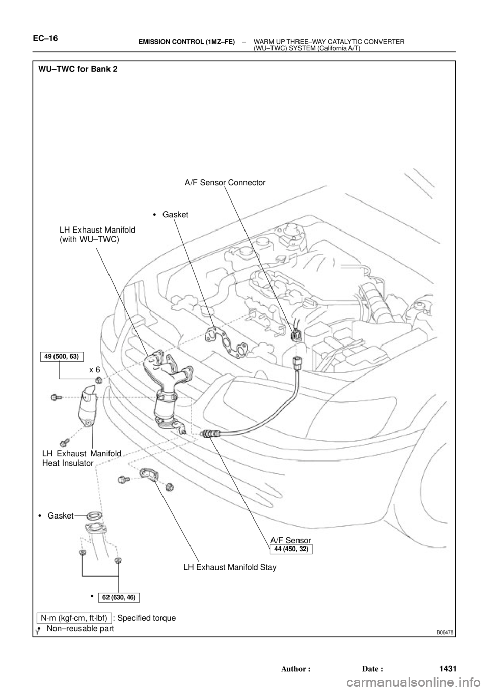
B06478
WU±TWC for Bank 2
LH Exhaust Manifold
(with WU±TWC)
LH Exhaust Manifold
Heat InsulatorA/F Sensor Connector
A/F Sensor
LH Exhaust Manifold Stay � Gasket� Gasket
49 (500, 63)
62 (630, 46)
44 (450, 32)
x 6
�
N´m (kgf´cm, ft´lbf) : Specified torque
� Non±reusable part
EC±16± EMISSION CONTROL (1MZ±FE)WARM UP THREE±WAY CATALYTIC CONVERTER
(WU±TWC) SYSTEM (California A/T)
1431 Author�: Date�:
Page 2550 of 4592
EC022±04
± EMISSION CONTROL (1MZ±FE)THREE±WAY CATALYTIC CONVERTER (TWC)
SYSTEMEC±17
1432 Author�: Date�:
THREE±WAY CATALYTIC CONVERTER (TWC) SYSTEM
ON±VEHICLE INSPECTION
1. INSPECT EXHAUST PIPE ASSEMBLY
(a) Check the connections for looseness or damage.
(b) Check the clamps for weakness, cracks or damage.
2. INSPECT TWC
Check for dents or damage.
If any part of the protector is damaged or dented to the extent that it contacts the TWC, repair or replace
it.
3. INSPECT TWC HEAT INSULATOR
(a) Check the heat insulator for damage.
(b) Check for adequate clearance between the catalytic converter and heat insulator.
Page 2551 of 4592
EC023±04
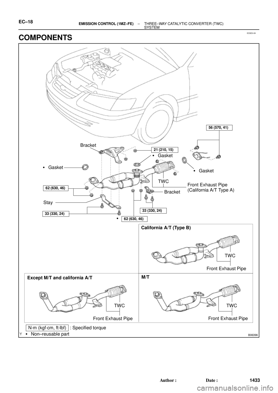
B06396
Except M/T and california A/TCalifornia A/T (Type B)
M/T
TWC
Front Exhaust Pipe
N´m (kgf´cm, ft´lbf) : Specified torque
� Non±reusable part
TWC
Front Exhaust Pipe
Bracket
� Gasket
Stay
62 (630, 46)
56 (570, 41)
TWC
Front Exhaust Pipe
(California A/T Type A)� Gasket � Gasket
�
62 (630, 46)
33 (330, 24)33 (330, 24)
Bracket
TWC
Front Exhaust Pipe
21 (210, 15)
EC±18± EMISSION CONTROL (1MZ±FE)THREE±WAY CATALYTIC CONVERTER (TWC)
SYSTEM
1433 Author�: Date�:
COMPONENTS
Page 2820 of 4592

± INTRODUCTIONFOR ALL OF VEHICLES
IN±17
17 Author�: Date�:
2. FOR VEHICLES EQUIPPED WITH A CATALYTIC CONVERTER
CAUTION:
If large amount of unburned gasoline flows into the converter, it may overheat and create a fire haz-
ard. To prevent this, observe the following precautions and explain them to your customer.
(a) Use only unleaded gasoline.
(b) Avoid prolonged idling.
Avoid running the engine at idle speed for more than 20 minutes.
(c) Avoid spark jump test.
(1) Perform spark jump test only when absolutely necessary. Perform this test as rapidly as possible.
(2) While testing, never race the engine.
(d) Avoid prolonged engine compression measurement.
Engine compression tests must be done as rapidly as possible.
(e) Do not run engine when fuel tank is nearly empty.
This may cause the engine to misfire and create an extra load on the converter.
(f) Avoid coasting with ignition turned off.
(g) Do not dispose of used catalyst along with parts contaminated with gasoline or oil.
3. IF VEHICLE IS EQUIPPED WITH MOBILE COMMUNICATION SYSTEM
For vehicles with mobile communication systems such as two±way radios and cellular telephones, observe
the following precautions.
(1) Install the antenna as far as possible away from the ECU and sensors of the vehicle's electronic
system.
(2) Install the antenna feeder at least 20 cm (7.87 in.) away from the ECU and sensors of the ve-
hicle's electronic systems. For details about ECU and sensors locations, refer to the section on
the applicable component.
(3) Avoid winding the antenna feeder together with other wiring as much as possible, and also avoid
running the antenna feeder parallel with other wire harnesses.
(4) Check that the antenna and feeder are correctly adjusted.
(5) Do not install powerful mobile communications system.