Page 1517 of 4592
(b)(c) (d)
Time Warmed up 3 min. or so")
FI7081
Waveform of Oxygen Sensor
before CatalystNormal Catalyst Waveform of Oxygen Sensor
after Catalyst
FI7132
Engine Speed
2,500 ~ 3,000 rpm
Idling
IG SW OFF(a)(b)(c) (d)
Time Warmed up 3 min. or so Check
± DIAGNOSTICSENGINE (1MZ±FE)
DI±305
540 Author�: Date�:
DTC P0420 Catalyst System Efficiency Below Threshold
(Except California Spec.)
CIRCUIT DESCRIPTION
The ECM compares the waveform of the oxygen sensor located before the catalyst with the waveform of
the oxygen sensor located after the catalyst to determine whether or not catalyst performance has deterio-
rated.
Air±fuel ratio feedback compensation keeps the waveform of the oxygen sensor before the catalyst repeat-
edly changing back and forth from rich to lean.
If the catalyst is functioning normally, the waveform of the oxygen sensor after the catalyst switches back
and forth between rich and lean much more slowly than the waveform of the oxygen sensor before the cata-
lyst.
But when both waveforms change at a similar rate, it indicates that catalyst performance has deteriorated.
DTC No.DTC Detecting ConditionTrouble Area
P0420
After engine and catalyst are warmed up, and while vehicle is
driven within set vehicle and engine speed range, waveforms
of heated oxygen sensors (bank 1 sensor 1, 2) have the same
amplitude
(2 trip detection logic)
�Three±way catalytic converter
�Open or short in heated oxygen sensor circuit
�Heated oxygen sensor
CONFIRMATION ENGINE RACING PATTERN
DI07Y±06
Page 1519 of 4592
± DIAGNOSTICSENGINE (1MZ±FE)
DI±307
542 Author�: Date�:
3 Check heated oxygen sensor (bank 1, sensor 1) (See page DI±255).
NG Repair or replace.
OK
4 Check heated oxygen sensors (bank 1, 2 sensor 2) (See page DI±265).
NG Repair or replace.
OK
Replace three±way catalytic converter.
Page 1520 of 4592

543 Author�: Date�:
DTC P0420 Catalyst System Eff")
A01674
Waveform of
A/F Sensor
Normal CatalystWaveform of Heated Oxygen
Sensor Behind Catalyst
Abnormal Catalyst DI±308
± DIAGNOSTICSENGINE (1MZ±FE)
543 Author�: Date�:
DTC P0420 Catalyst System Efficiency Below Threshold
(Only for California Spec.)
CIRCUIT DESCRIPTION
The ECM observes the waveform of the heated oxygen sensor located behind the catalyst to determine
whether the catalyst is performance has deteriorated.
If the catalyst is functioning normally, the waveform of the heated oxygen sensor located behind the catalyst
switches back and forth between rich and lean much more slowly.
When the waveform of the heated oxygen sensor located behind the catalyst alternates flatteringly between
rich and lean, it indicates that catalyst performance has deteriorated.
DTC No.DTC Detecting ConditionTrouble Area
P0420
After engine and catalyst are warmed up, and while vehicle is
driven within set vehicle and engine speed range, waveform of
heated oxygen sensor (bank 1 sensor 2) alternates flatteringly
between rich and lean
(2 trip detection logic)�Three±way catalytic converter
�Open or short in heated oxygen sensor
(bank 1 sensor 2) circuit
�Heated oxygen sensor (bank 1 sensor 2)
�Open or short in A/F sensors (bank 1, 2 sensor 1) circuit
�A/F sensors (bank 1, 2 sensor 1)
DI1K4±03
Page 1522 of 4592
DI±310
± DIAGNOSTICSENGINE (1MZ±FE)
545 Author�: Date�:
3 Check A/F sensors (bank 1, 2 sensor 1) (See page DI±255).
NG Repair or replace.
OK
4 Check heated oxygen sensor (bank 1 sensor 2) (See page DI±265).
NG Repair or replace.
OK
Replace three±way catalytic converter.
Page 2191 of 4592

Platinum
Electrode
Heater
Air±Fuel Ratio
(V)
2.6 4.0
3.8
3.6
3.4
3.2
3.0
2.8
2.4
14 15 16 17 19 21 22
Coatin")
A00477
Atmosphere
Cover
Exhaust GasPlatinum
Electrode
Solid Electrolyte
(Zirconia Element)
Platinum
Electrode
Heater
Air±Fuel Ratio
(V)
2.6 4.0
3.8
3.6
3.4
3.2
3.0
2.8
2.4
14 15 16 17 19 21 22
Coating (Ceramic)
ECM Monitored
A/F Sensor Voltage
DI±40
± DIAGNOSTICSENGINE
DTC P0125 Insufficient Coolant Temp. for Closed Loop
Fuel Control
CIRCUIT DESCRIPTION
To obtain a high purification rate for the CO, HC and NOx components of the exhaust gas, a three±way cata-
lytic converter is used, but for the most efficient use of the three±way catalytic converter, the air±fuel ratio
must be precisely controlled so that it is always close to the stoichiometric air±fuel ratio.
The A/F sensor has the characteristic that provides output voltage
* approximately proportional to the exist-
ing air±fuel ratio. The A/F sensor output voltage
* is used to provide feedback for the ECM to control the air±
fuel ratio.
By the A/F sensor output, the ECM can determine the deviation amount from the stoichiometric air±fuel ratio
and control the proper injection time immediately. If the A/F sensor is malfunctioning, ECM is unable to per-
form accurate air±fuel ratio control.
The A/F sensor is equipped with a heater which heats the zirconia element. The heater is controlled by the
ECM. When the intake air volume is low (the temp. of the exhaust gas is low), current flows to the heater
to heat the sensor for accurate oxygen concentration detection.
*: The voltage value changes at the inside of the ECM only.
DTC No.DTC Detecting ConditionTrouble Area
P0125
After engine is warmed up, A/F sensor output* does not
change when conditions (a), (b) and (c) continue for at least
1.5 min.:
*: Output value changes at inside of ECM only
(a) Engine speed: 1,500 rpm or more
(b) Vehicle speed: 40 ± 100 km/h (25 ± 62 mph)
(c) Throttle valve is not fully closed�Open or short in A/F sensor (bank 1 sensor 1) circuit
�A/F sensor (bank 1 sensor 1)
�Air induction system
�EGR system
�Fuel pressure
�Injector
�Gas leakage on exhaust system
�ECM
HINT:
�After confirming DTC P0125, use the OBD II scan tool or TOYOTA hand-held tester to confirm voltage
output of A/F sensor from the CURRENT DATA.
�The ECM controls the voltage of the AF+ and AF± terminals of the ECM to the fixed voltage. Therefore,
it is impossible to confirm the A/F sensor output voltage without OBD II scan tool or TOYOTA hand±
held tester.
DI1JU±04
Page 2517 of 4592
EC039±05
± EMISSION CONTROL (5S±FE)EMISSION CONTROL SYSTEM
EC±1
1399 Author�: Date�:
EMISSION CONTROL SYSTEM
PURPOSE
The emission control systems are installed to reduce the amount of HC, CO and NOx exhausted from the
engine ((3), (4) and (5)), to prevent the atmospheric release of blow±by gas±containing HC (1) and evapo-
rated fuel containing HC being released from the fuel tank (2).
The function of each system is shown in the following table.
SystemAbbreviationFunction
(1) Positive Crankcase Ventilation
(2) Evaporative Emission Control
(3) Exhaust Gas Recirculation
(4) Three±Way Catalytic Converter
(5) Sequential Multiport Fuel Injection*PCV
EVAP
EGR
TWC
SFIReduces HC
Reduces evaporated HC
Reduces NOx
Reduces HC, CO and NOx
Injects a precisely timed, optimum amount of fuel for reduced
exhaust emissions
Remark: * For inspection and repair of the SFI system, refer to the SFI section in this manual.
Page 2531 of 4592
EC03H±03
± EMISSION CONTROL (5S±FE)THREE±WAY CATALYTIC CONVERTER (TWC)
SYSTEMEC±15
1413 Author�: Date�:
THREE±WAY CATALYTIC CONVERTER (TWC) SYSTEM
ON±VEHICLE INSPECTION
1. INSPECT EXHAUST PIPE ASSEMBLY
(a) Check the connections for looseness or damage.
(b) Check the clamps for weakness, cracks or damage.
2. INSPECT REAR TWC
Check for dents or damage.
If any part of the protector is damaged or dented to the extent that it contacts the TWC, repair or replace
it.
3. INSPECT REAR TWC HEAT INSULATOR
(a) Check the heat insulator for damage.
(b) Check for adequate clearance between the catalytic converter and heat insulator.
Page 2532 of 4592
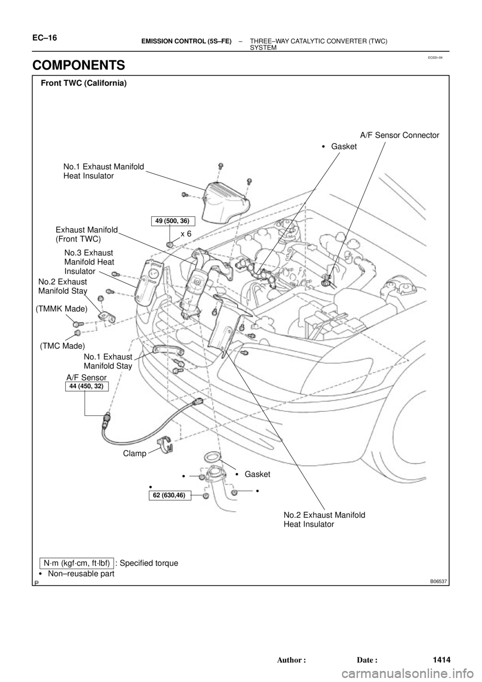
EC03I±04
B06537
Front TWC (California)
Exhaust Manifold
(Front TWC)
No.3 Exhaust
Manifold Heat
Insulator
No.2 Exhaust
Manifold Stay
A/F Sensor� GasketA/F Sensor Connector
� Gasket Clampx 6
�
�
N´m (kgf´cm, ft´lbf)
� Non±reusable part
49 (500, 36)
44 (450, 32)
62 (630,46)
: Specified torque
No.1 Exhaust
Manifold Stay
�
No.1 Exhaust Manifold
Heat Insulator
No.2 Exhaust Manifold
Heat Insulator
(TMC Made)
(TMMK Made)
EC±16± EMISSION CONTROL (5S±FE)THREE±WAY CATALYTIC CONVERTER (TWC)
SYSTEM
1414 Author�: Date�:
COMPONENTS