Page 1223 of 4592
A07370S05309A07664
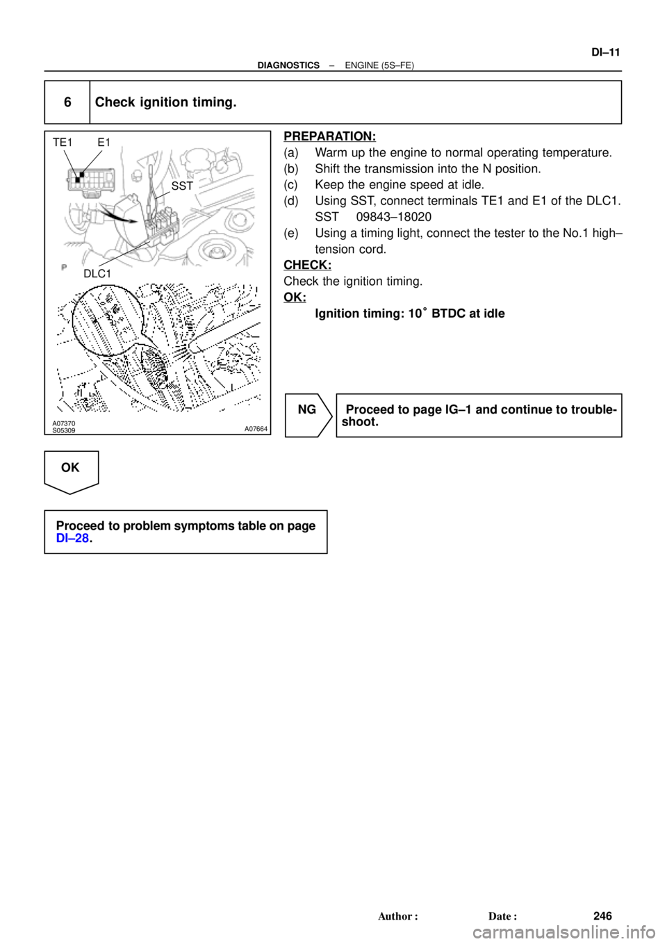
E1 TE1
SST
DLC1
± DIAGNOSTICSENGINE (5S±FE)
DI±11
246 Author�: Date�:
6 Check ignition timing.
PREPARATION:
(a) Warm up the engine to normal operating temperature.
(b) Shift the transmission into the N position.
(c) Keep the engine speed at idle.
(d) Using SST, connect terminals TE1 and E1 of the DLC1.
SST 09843±18020
(e) Using a timing light, connect the tester to the No.1 high±
tension cord.
CHECK:
Check the ignition timing.
OK:
Ignition timing: 10° BTDC at idle
NG Proceed to page IG±1 and continue to trouble-
shoot.
OK
Proceed to problem symptoms table on page
DI±28.
Page 1231 of 4592

DI±19
254 Author�: Date�:
DTC No.
(See Page)Detection ItemTrouble AreaMIL*1Memory
P0500
(DI±145)Vehicle Speed Sensor
Malfunction
�Combination meter
�Open or short in N")
± DIAGNOSTICSENGINE (5S±FE)
DI±19
254 Author�: Date�:
DTC No.
(See Page)Detection ItemTrouble AreaMIL*1Memory
P0500
(DI±145)Vehicle Speed Sensor
Malfunction
�Combination meter
�Open or short in No.1 vehicle speed sensor circuit
�No.1 vehicle speed sensor
�ECM
��
P0505
(DI±148)Idle Control System
Malfunction
�IAC valve is stuck or closed
�Open or short in IAC valve circuit
�Open or short in A/C switch circuit
�Air intake (hose loose)
�ECM
��
*1: ����� MIL lights up
2. MANUFACTURER CONTROLLED
DTC No.
(See Page)Detection ItemTrouble AreaMIL*1Memory
*2
P1130
(DI±152)A/F Sensor Circuit
Range/Performance Malfunction�Open or short in A/F sensor circuit
�A/F sensor
�ECM
��
*2
P1133
(DI±157)A/F Sensor Circuit Response
Malfunction�A/F sensor��
*2
P1135
(DI±161)A/F Sensor Heater Circuit
Malfunction�Open or short in heater circuit of A/F sensor
�A/F sensor heater
�ECM
��
P1300
(DI±163)Igniter Circuit Malfunction (No.1)
�Open or short in IGF or IGT circuit from igniter to ECM
�Ignition coil (No.1)
�ECM
��
P1310
(DI±163)Igniter Circuit Malfunction (No.2)
�Open or short in IGF or IGT circuit from igniter to ECM
�Ignition coil (No.2)
�ECM
��
P1335
(DI±169)Crankshaft Position Sensor Cir-
cuit Malfunction
(During engine running)�Open short in crankshaft position sensor circuit
�Crankshaft position sensor
�ECM
±�
*3
P1520
(DI±170)Stop Light Switch Signal Mal-
function�Short in stop light switch signal circuit
�Stop light switch
�ECM
��
P1600
(DI±173)ECM BATT Malfunction�Open in back up power source circuit
�ECM��
*3
P1780
(DI±175)Park/Neutral Position Switch
Malfunction�Short in park/neutral position switch circuit
�Park/neutral position switch
�ECM
��
*1: ����� MIL lights up
*
2: Only for California Specification vehicles
*
3: Only for A/T models
Page 1233 of 4592
DI1JS±03
A03431
A03430
A03537
Crankshaft
Position
SensorVSV for EGRDLC1Camshaft Position
SensorInjectorECMThrottle Position SensorManifold Absolute
Pressure Sensor
Combination Meter
(Speedometer)
DLC3
Heated Oxygen
Sensor
(Bank 1 Sensor 2)
Intake Air Temp.
Sensor
VSV for EVAP
Idle Air Control
Valve
Ignition Coil (No.1, No.2) Park/Neutral Position
Switch Engine Coolant Temp.
Sensor Heated Oxygen Sensor
(Bank 1 Sensor 1) *1 A/F Sensor *2 Knock
Sensor 1
*1: Except California Specification vehicles
*2: Only for California Specification vehicles
Vapor Pressure Sensor
Charcoal Canister
VSV for
Vapor Pressure Sensor
± DIAGNOSTICSENGINE (5S±FE)
DI±21
256 Author�: Date�:
PARTS LOCATION
Page 1240 of 4592

263 Author�: Date�:
PROBLEM SYMPTOMS TABLE
SymptomSuspect AreaSee page
Engine does not crank (Does not start)1. Starter
2. starter relayST±2
ST±20
No i")
DI00L±03
DI±28
± DIAGNOSTICSENGINE (5S±FE)
263 Author�: Date�:
PROBLEM SYMPTOMS TABLE
SymptomSuspect AreaSee page
Engine does not crank (Does not start)1. Starter
2. starter relayST±2
ST±20
No initial combustion (Does not start)
1. ECM power source circuit
2. Fuel pump control circuit
3. Engine control module (ECM)DI±179
DI±183
IN±31
No complete combustion (Does not start)1. Fuel pump control circuitDI±183
Engine cranks normally (Difficult to start)
1. Starter signal circuit
2. Fuel pump control circuit
3. CompressionDI±176
DI±183
EM±3
Cold engine (Difficult to start)1. Starter signal circuit
2. Fuel pump control circuitDI±176
DI±183
Hot engine (Difficult to start)1. Starter signal circuit
2. Fuel pump control circuitDI±176
DI±183
High engine idle speed (Poor idling)1. A/C switch circuit
2. ECM power source circuitAC±84
DI±179
Low engine idle speed (Poor idling)1. A/C switch circuit
2. Fuel pump control circuit AC±84
DI±183
Rough idling (Poor idling)1. Compression
2. Fuel pump control circuitEM±3
DI±183
Hunting (Poor idling)1. ECM power source circuit
2. Fuel pump control circuitDI±179
DI±183
Hesitation/Poor acceleration (Poor driveability)1. Fuel pump control circuit
2. A/T faulty DI±183
DI±405
Surging (Poor driveability)1. Fuel pump control circuitDI±183
Soon after starting (Engine stall)1. Fuel pump control circuitDI±183
During A/C operation (Engine stall)1. A/C switch circuit
2. Engine control module (ECM) AC±84
IN±31
A/C switch indicatior blinking1. A/C Compressor lock sensor circuit
2. A/C Evaporator temp. sensor circuitDI±190
DI±192
Unable to refuel/ Difficult to refuel1. ORVR systemEC±6
Page 1279 of 4592

Idling
IG SW OFF
(1)
1 ~ 3 min.1 min.Time
(2)(3)(4)
(5)
± DIAGNOSTICSENGINE (5S±FE)
DI±67
302 Author�: Date�:
CONFIRMATION DRIVING PATTERN
(1) Connec")
A01666
Vehicle speed
50 ~ 65 km/h
(31 ~ 40 mph)
Idling
IG SW OFF
(1)
1 ~ 3 min.1 min.Time
(2)(3)(4)
(5)
± DIAGNOSTICSENGINE (5S±FE)
DI±67
302 Author�: Date�:
CONFIRMATION DRIVING PATTERN
(1) Connect the TOYOTA hand±held tester to the DLC3.
(2) Switch the TOYOTA hand±held tester from normal mode to check mode (See page DI±3).
(3) Start the engine and warm it up with all accessory switches OFF.
(4) Drive the vehicle at 50 ~ 65 km/h (31 ~ 40 mph) for 1 ~ 3 min. to warm up the heated oxygen sensor.
(5) Let the engine idle for 1 min.
(6) Perform steps (3) to (5) three times.
HINT:
If a malfunction exists, the MIL will light up during step (6).
NOTICE:
If the conditions in this test are not strictly followed, detection of the malfunction will not be possible.
If you do not have a TOYOTA hand±held tester, turn the ignition switch OFF after performing steps
(3) to (6), then perform steps (3) to (6) again.
INSPECTION PROCEDURE
HINT:
Read freeze frame data using TOYOTA hand±held tester or OBD II scan tool. Because freeze frame records
the engine conditions when the malfunction is detected, when troubleshooting it is useful for determining
whether the vehicle was running or stopped, the engine warmed up or not, the air±fuel ratio lean or rich, etc.
at the time of the malfunction.
1 Are there any other codes (besides DTC P0130) being output?
YES Go to relevant DTC chart.
NO
Page 1319 of 4592

Idling
IG SW OFF
(1)(2)
Warm up
3 ~ 5 min.2 min.
3 ~ 5 min.Time (3)
(4)
(5)(6)
(7)
2 min.
± DIAGNOSTICSENGINE (5S±FE)
DI±107
342 Author�: Date�:
SYST")
P20769
Vehicle Speed
60 ~ 80 km/h
(38 ~ 50 mph)
Idling
IG SW OFF
(1)(2)
Warm up
3 ~ 5 min.2 min.
3 ~ 5 min.Time (3)
(4)
(5)(6)
(7)
2 min.
± DIAGNOSTICSENGINE (5S±FE)
DI±107
342 Author�: Date�:
SYSTEM CHECK DRIVING PATTERN
(1) Connect the OBD II scan tool or TOYOTA hand±held tester to the DLC3.
(2) Start and warm up the engine with all accessories switched OFF.
(3) Run the vehicle at 60 ~ 80 km/h (38 ~ 50 mph) for 3 min. or more.
(4) Idle the engine for about 2 min.
(5) Do steps (3) and (4) again.
(6) Stop at safe place and turn the ignition switch OFF.
(7) Do steps (2) to (5) again.
(8) Check the READINESS TESTS mode on the OBD II scan tool or TOYOTA hand±held tester.
If COMPL is displayed and the MIL does not light up, the system is normal.
If INCMPL is displayed and the MIL does not light up, run the vehicle again and check it.
HINT:
INCMPL is displayed when either condition (a) or (b) exists.
(a) The system check is incomplete.
(b) There is a malfunction in the system.
If there is a malfunction in the system, the MIL will light up after steps (2) to (5) above are done.
(2 trip detection logic)
INSPECTION PROCEDURE
HINT:
�If DTC P0105 (Manifold Absolute Pressure/Barometric Pressure Circuit Malfunction), P0106 (Manifold
Absolute Pressure/Barometric Pressure Circuit Range/Performance Problem) and P0401 (Exhaust
Gas Recirculation Flow Insufficient Detected) are output simultaneously, perform troubleshooting of
DTC P0105 first.
�If DTC P0401 (Exhaust Gas Recirculation Flow Insufficient Detected) and P0402 (Exhaust Gas Recir-
culation Flow Excessive Detected) are output simultaneously, perform troubleshooting of DTC P0402
first.
�Read freeze frame data using TOYOTA hand±held tester or OBD II scan tool. Because freeze frame
records the engine conditions when the malfunction is detected, when troubleshooting it is useful for
determining whether the vehicle was running or stopped, the engine warmed up or not, the air±fuel
ratio lean or rich, etc. at the time of the malfunction.
Page 1360 of 4592

P01559
Throttle Valve
To Cylinder ECM Signal From
Air
Cleaner
Valve
IAC Valve
Intake Air
Chamber
A07553
B±Y 9
2B±Y B±Y
II3J19
J/CIAC ValveECM
1
3 2
B
EFI
5
1 Engine Room J/B No.2
42
2J
W±B
B
ISCO
E01
E01 ISCC10
9W
B±OE9
E9
1
2A
2K
EFI Relay
EB
From
BatteryB
*1: w/o Immobiliser
*2: w/ Immobiliser(*1) (*2)
E97
E96
(*2) (*1)
E107MREL2FB±W B±W
II4
(*2)
7
6(*2) (*2)
3
B±R
(*1)From
Ignition SW DI±148
± DIAGNOSTICSENGINE (5S±FE)
383 Author�: Date�:
DTC P0505 Idle Control System Malfunction
CIRCUIT DESCRIPTION
The rotary solenoid type IAC valve is located on the throttle
body and intake air bypassing the throttle valve is directed to
the IAC valve through a passage.
In this way the intake air volume bypassing the throttle valve is
regulated, controlling the engine speed.
The ECM operates only the IAC valve to perform idle±up and
provide feedback for the target idling speed.
DTC No.DTC Detecting ConditionTrouble AreaTrouble Area
P0505Idle speed continues to vary greatly from the target speed
(2 trip detection logic)
�IAC valve is stuck or closed
�Open or short in IAC valve circuit
�Open or short in A/C switch circuit
�Air intake (hose loose)
�ECM
WIRING DIAGRAM
DI01C±05
Page 1361 of 4592

DI±149
384 Author�: Date�:
INSPECTION PROCEDURE
HINT:
Read freeze frame data using TOYOTA hand±held tester or OBD II scan tool. Because freeze frame records
the engine")
± DIAGNOSTICSENGINE (5S±FE)
DI±149
384 Author�: Date�:
INSPECTION PROCEDURE
HINT:
Read freeze frame data using TOYOTA hand±held tester or OBD II scan tool. Because freeze frame records
the engine conditions when the malfunction is detected, when troubleshooting it is useful for determining
whether the vehicle was running or stopped, the engine warmed up or not, the air±fuel ratio lean or rich, etc.
at the time of the malfunction.
1 Check idle speed.
PREPARATION:
(a) Warm up the engine to normal operating temperature.
(b) Switch off all the accessories.
(c) Switch off the air conditioning.
(d) Shift the transmission into N or neutral position.
(e) Connect the OBD II scan tool or TOYOTA hand±held tester to the DLC3 on the vehicle.
(f) Using SST, connect terminals TE1 and E1 of the DLC1.
CHECK:
Check the difference of engine speed between the ones less than 5 sec. and more than 5 sec. after connect-
ing terminals TE1 and E1 of the DLC1.
OK:
Difference of engine speed: More than 100 rpm
OK Go to step 6.
NG

DL")