Page 2226 of 4592
± DIAGNOSTICSENGINE
DI±75
OK
7 Check for open and short in harness and connector in RSD circuit.
NG Repair or replace.
OK
Replace IAC valve.
8 Check for A/C signal circuit (See Pub. No. RM654U, page AC±84).
NG Repair or replace.
OK
Check air induction system
(See page SF±1).
OBD II scan tool (excluding TOYOTA hand±held tester):
1 Check idle speed.
PREPARATION:
(a) Warm up the engine to normal operating temperature.
(b) Switch off all the accessories.
(c) Switch off the A/C.
(d) Shift the transmission into the N or neutral position.
(e) Remove the fuse cover on the instrument panel.
(f) Connect the OBD II scan tool to the DLC3 on the vehicle.
(g) Using SST, connect terminals TE1 and E1 of the DLC1.
SST 09843±18020
CHECK:
Check the difference of engine speed between the ones, less than 5 sec. and more than 5 sec. after connect-
ing terminals TE1 and E1 of the DLC1.
OK:
Difference of engine speed: More than 100 rpm
Page 2263 of 4592

DI±112
± DIAGNOSTICSENGINE
DTC P1780 Park/Neutral Position Switch Malfunction
CIRCUIT DESCRIPTION
The park/neutral position switch goes on when the shift lever is in the N or P shift position. When it goes on
terminal NSW of the ECM is grounded to body ground via the starter relay thus the terminal NSW voltage
becomes 0V. When the shift lever is in the D, 2, L or R position, the park/neutral position switch goes off,
so the voltage of ECM. Terminal NSW becomes battery positive voltage, the voltage of the ECM internal
power source.
If the shift lever is moved from the N position to the D position, this signal is used for air±fuel ratio correction
and for idle speed control (estimated control), etc.
DTC No.DTC Detecting ConditionTrouble Area
2 or more switches are ON simultaneously for P, R, N, D, 2
and L positions (2 trip detection logic)
P1780
When driving under conditions (a) and (b) for 30 sec. or more
park/neutral position switch is ON (N position):
(2 trip detection logic)
(a) Vehicle speed: 80 km/h (50 mph) or more
(b) Engine speed: 2,000 ± 5,000 rpm�Short in park/neutral position switch circuit
�Park/neutral position switch
�ECM
HINT:
After confirming DTC P1780, use the TOYOTA hand±held tester to confirm the PNP switch signal from the
CURRENT DATA.
WIRING DIAGRAM
Refer to DTC P1780 on page DI±165.
INSPECTION PROCEDURE
HINT:
Read freeze frame data using TOYOTA hand±held tester or OBD II scan tool. Because freeze frame records
the engine conditions when the malfunction is detected. When troubleshooting it is useful for determining
whether the vehicle was running or stopped, the engine was warmed up or not, the air±fuel ratio was lean
or rich, etc. at the time of the malfunction.
Refer to DTC P1780 on page DI±165.
DI01J±07
Page 2264 of 4592

DI±112
± DIAGNOSTICSENGINE
DTC P1780 Park/Neutral Position Switch Malfunction
CIRCUIT DESCRIPTION
The park/neutral position switch goes on when the shift lever is in the N or P shift position. When it goes on
terminal NSW of the ECM is grounded to body ground via the starter relay thus the terminal NSW voltage
becomes 0V. When the shift lever is in the D, 2, L or R position, the park/neutral position switch goes off,
so the voltage of ECM. Terminal NSW becomes battery positive voltage, the voltage of the ECM internal
power source.
If the shift lever is moved from the N position to the D position, this signal is used for air±fuel ratio correction
and for idle speed control (estimated control), etc.
DTC No.DTC Detecting ConditionTrouble Area
2 or more switches are ON simultaneously for P, R, N, D, 2
and L positions (2 trip detection logic)
P1780
When driving under conditions (a) and (b) for 30 sec. or more
park/neutral position switch is ON (N position):
(2 trip detection logic)
(a) Vehicle speed: 80 km/h (50 mph) or more
(b) Engine speed: 2,000 ± 5,000 rpm�Short in park/neutral position switch circuit
�Park/neutral position switch
�ECM
HINT:
After confirming DTC P1780, use the TOYOTA hand±held tester to confirm the PNP switch signal from the
CURRENT DATA.
WIRING DIAGRAM
Refer to DTC P1780 on page DI±165.
INSPECTION PROCEDURE
HINT:
Read freeze frame data using TOYOTA hand±held tester or OBD II scan tool. Because freeze frame records
the engine conditions when the malfunction is detected. When troubleshooting it is useful for determining
whether the vehicle was running or stopped, the engine was warmed up or not, the air±fuel ratio was lean
or rich, etc. at the time of the malfunction.
Refer to DTC P1780 on page DI±165.
DI01J±07
Page 2292 of 4592

Q00199
Q01561
P
R
N
AT4478
Neutral Basic line
Groove
DI±140
± DIAGNOSTICSAUTOMATIC TRANSAXLE
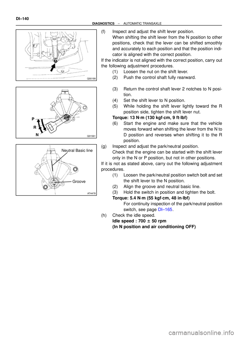
(f) Inspect and adjust the shift lever position.
When shifting the shift lever from the N position to other
positions, check that the lever can be shifted smoothly
and accurately to each position and that the position indi-
cator is aligned with the correct position.
If the indicator is not aligned with the correct position, carry out
the following adjustment procedures.
(1) Loosen the nut on the shift lever.
(2) Push the control shaft fully rearward.
(3) Return the control shaft lever 2 notches to N posi-
tion.
(4) Set the shift lever to N position.
(5) While holding the shift lever lightly toward the R
position side, tighten the shift lever nut.
Torque: 13 N´m (130 kgf´cm, 9 ft´lbf)
(6) Start the engine and make sure that the vehicle
moves forward when shifting the lever from the N to
D position and reverses when shifting it to the R
position.
(g) Inspect and adjust the park/neutral position.
Check that the engine can be started with the shift lever
only in the N or P position, but not in other positions.
If it is not as stated above, carry out the following adjustment
procedures.
(1) Loosen the park/neutral position switch bolt and set
the shift lever to the N position.
(2) Align the groove and neutral basic line.
(3) Hold the switch in position and tighten the bolt.
Torque: 5.4 N´m (55 kgf´cm, 48 in´lbf)
For continuity inspection of the park/neutral position
switch, see page DI±165.
(h) Check the idle speed.
Idle speed : 700 ± 50 rpm
(In N position and air conditioning OFF)
Page 2294 of 4592

DI±142
± DIAGNOSTICSAUTOMATIC TRANSAXLE
(b) Measure the time lag.
When the shift lever is shifted while the engine is idling, there will be a certain time lapse or lag before
the shock can be felt. This is used for checking the condition of the O/D direct clutch, forward clutch,
and 1st & reverse brake.
NOTICE:
�Do the test at normal operating fluid temperature 50 ± 80 °C (122 ± 176 °F).
�Be sure to allow 1 minute interval between tests.
�Take 3 measurements and take the average value.
(1) Connect an OBD II scan tool or hand±held tester to DLC3.
(2) Fully apply the parking brake.
(3) Start the engine and check idle speed.
Idle speed: 700 ± 50 rpm (In N position and air conditioning OFF)
(4) Shift the shift lever from N to D position. Using a stop watch, measure the time from when the
lever is shifted until the shock is felt.
Time lag: N " D Less than 1.2 seconds
(5) In the same manner, measure the time lag for N " R.
Time lag: N " R Less than 1.5 seconds
Evaluation (If N " D time or N " R time lag is longer than the specified):
ProblemPossible cause
N " D time lag is longer
�Line pressure too low
�Forward clutch worn
�O/D one±way clutch not operating
N " R time lag is longer
�Line pressure too low
�Direct clutch worn
�1st & reverse brake worn
�O/D one±way clutch not operating properly
Page 2495 of 4592
N21220
Cruise Control ECU
IDL 13
L±R ECM
IDLOE43
C16
± DIAGNOSTICSCRUISE CONTROL SYSTEM
DI±343
DTC 51 Idle Signal Circuit
CIRCUIT DESCRIPTION
When the idle switch is turned ON, a signal is sent to the ECU. The ECU uses this signal to correct the dis-
crepancy between the throttle valve position and the actuator position sensor value to enable accurate
cruise control at the set speed. If the idle switch is malfunctioning, problem symptoms also occur in the en-
gine, so also inspect the engine.
DTC No.DTC Detecting ConditionTrouble Area
51Short in idle signal circuit.
�Harness or connector between ECM and throttle position
sensor
�Throttle position sensor
�Harness or connector between cruise control ECU and ECM
�Cruise control ECU
WIRING DIAGRAM
DI08S±11
Page 2560 of 4592

EM080±03
S05331
A07370
SST
E1
TE1
S05309
± ENGINE MECHANICAL (5S±FE)IGNITION TIMING
EM±9
1181 Author�: Date�:
IGNITION TIMING
INSPECTION
1. WARM UP ENGINE
Allow the engine to warm up to normal operating temperature.
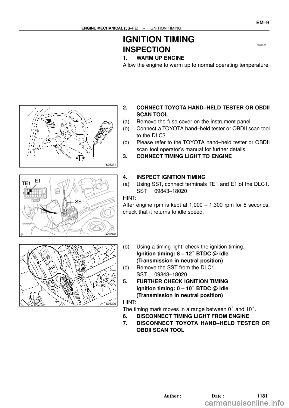
2. CONNECT TOYOTA HAND±HELD TESTER OR OBDII
SCAN TOOL
(a) Remove the fuse cover on the instrument panel.
(b) Connect a TOYOTA hand±held tester or OBDII scan tool
to the DLC3.
(c) Please refer to the TOYOTA hand±held tester or OBDII
scan tool operator's manual for further details.
3. CONNECT TIMING LIGHT TO ENGINE
4. INSPECT IGNITION TIMING
(a) Using SST, connect terminals TE1 and E1 of the DLC1.
SST 09843±18020
HINT:
After engine rpm is kept at 1,000 ± 1,300 rpm for 5 seconds,
check that it returns to idle speed.
(b) Using a timing light, check the ignition timing.
Ignition timing: 8 ± 12° BTDC @ idle
(Transmission in neutral position)
(c) Remove the SST from the DLC1.
SST 09843±18020
5. FURTHER CHECK IGNITION TIMING
Ignition timing: 0 ± 10° BTDC @ idle
(Transmission in neutral position)
HINT:
The timing mark moves in a range between 0° and 10°.
6. DISCONNECT TIMING LIGHT FROM ENGINE
7. DISCONNECT TOYOTA HAND±HELD TESTER OR
OBDII SCAN TOOL
Page 2561 of 4592

EM081±05
S05331
EM±10
± ENGINE MECHANICAL (5S±FE)IDLE SPEED
1182 Author�: Date�:
IDLE SPEED
INSPECTION
1. INITIAL CONDITIONS
(a) Engine at normal operating temperature
(b) Air cleaner installed
(c) All pipes and hoses of air induction system connected
(d) All vacuum lines properly connected
(e) SFI system wiring connectors fully plugged
(f) All operating accessories switched OFF
(g) Ignition timing check correctly
(h) Transmission in neutral position
(i) Air conditioning switched OFF
2. CONNECT TOYOTA HAND±HELD TESTER OR OBDII
SCAN TOOL
(a) Remove the fuse cover on the instrument panel.
(b) Connect a TOYOTA hand±held tester or OBDII scan tool
to the DLC3.
(c) Please refer to the TOYOTA hand±held tester or OBDII
scan tool operator's manual for further details.
3. INSPECT IDLE SPEED
(a) Race the engine at 2,500 rpm for approx. 90 seconds.
(b) Check the idle speed.
Idle speed (w/ Cooling fan OFF): 700 ± 50 rpm
If the idle speed is not as specified, check the IAC valve and air
intake system.
4. DISCONNECT TOYOTA HAND±HELD TESTER OR
OBDII SCAN TOOL