Page 3646 of 4592
SA08A±03
F08046
F08047
F08081
SA±18
± SUSPENSION AND AXLEREAR SHOCK ABSORBER
REMOVAL
1. REMOVE REAR SEATBACK AND REAR SEAT CUSH-
ION (See page BO±22)
2. REMOVE REAR WHEEL
3. DISCONNECT FLEXIBLE HOSE AND ABS SPEED
SENSOR WIRE HARNESS CLAMP FROM SHOCK AB-
SORBER
Remove the 2 bolts and disconnect the flexible hose bracket
and ABS wire harness clamp.
4. DISCONNECT STABILIZER BAR LINK FROM SHOCK
ABSORBER
Remove the nut and stabilizer bar link.
HINT:
If the ball joint turns together with the nut, use a 5 mm hexagon
wrench to hold the stud.
5. REMOVE SHOCK ABSORBER WITH COIL SPRING
(a) Loosen the 2 nuts on the lower side of the shock absorber.
(b) Remove the cap.
(c) Loosen the nut in the center of the suspension support.
NOTICE:
Do not remove it.
HINT:
If not disassembling the shock absorber, it is not necessary to
loosen the nut.
(d) Remove the 3 nuts and shock absorber with the coil
spring.
Page 3647 of 4592

SA1F5±02
± SUSPENSION AND AXLEREAR SHOCK ABSORBER
SA±19
INSTALLATION
1. INSTALL SHOCK ABSORBER WITH COIL SPRING
(a) Install the 3 nuts and shock absorber with the coil spring.
Torque: 39 N´m (400 kgf´cm, 29 ft´lbf)
(b) Install the shock absorber with the coil spring, 2 bolts and nuts.
Torque:
Reused nut: 196 N´m (2,000 kgf´cm, 145 ft´lbf)
New nut: 255 N´m (2,600 kgf´cm, 188 ft´lbf)
HINT:
If reusing the 2 nuts, coat the threads of the 2 nuts with engine oil.
(c) Torque the nut in the center of the suspension support.
Torque: 49 N´m (500 kgf´cm, 36 ft´lbf)
HINT:
If the shock absorber has not been disassembled, it is not necessary to torque the nut.
(d) Install the cap.
2. CONNECT STABILIZER BAR LINK
Torque: 39 N´m (400 kgf´cm, 29 ft´lbf)
HINT:
If the ball joint turns together with the nut, use a hexagon (5 mm) wrench to hold the stud.
3. CONNECT FLEXIBLE HOSE AND ABS SPEED SENSOR WIRE HARNESS CLAMP
Torque:
Flexible hose: 29 N´m (300 kgf´cm, 22 ft´lbf)
ABS speed sensor wire harness: 5.4 N´m (55 kgf´cm, 48 in.´lbf)
4. INSTALL REAR WHEEL
Torque: 103 N´m (1,050 kgf´cm, 76 ft´lbf)
5. INSTALL REAR SEATBACK AND REAR SEAT CUSHION (See page BO±25)
6. CHECK REAR WHEEL ALIGNMENT (See Pub. No. RM654U on page SA±7)
Page 3648 of 4592
SA1F6±02
F08049
N´m (kgf´cm, ft´lbf) : Specified torque
Non±reusable part �
56 (570, 41)
181 (1,850, 134)
181 (1,850, 134)
113 (1,150, 83)
5.4 (55, 48 in.´lbf)
113 (1,150, 83)
Suspension Member
Adjusting
Tube
Suspension
Arm Washer
No. 2 Lower Suspension Arm
No. 1 Lower Suspension Arm
Parking Brake Cable
Strut Rod
SA±20
± SUSPENSION AND AXLEREAR LOWER SUSPENSION ARM AND STRUT ROD
527 Author�: Date�:
REAR LOWER SUSPENSION ARM AND STRUT ROD
COMPONENTS
Page 3649 of 4592
SA1JS±01
F08073
F08074
F08075
± SUSPENSION AND AXLEREAR LOWER SUSPENSION ARM AND STRUT ROD
SA±21
REMOVAL
1. REMOVE REAR WHEEL
2. REMOVE STRUT ROD
(a) Remove the bolt and disconnect the parking brake cable.
(b) Remove the 2 bolts, nuts and strut rod.
NOTICE:
Loossen the bolt since the nut cannot be rotated.
3. REMOVE NO. 2 LOWER SUSPENSION ARM
(a) Remove the 3 nuts, suspension arm washer and washer.
(b) Remove the No. 2 lower suspension arm and washer.
4. REMOVE NO. 1 LOWER SUSPENSION ARM
Remove the 2 bolts with the washer and No. 1 lower suspension
arm.
Page 3650 of 4592

SA1JT±01
F08076
Rear
F08051
Rear
F08050
SA±22
± SUSPENSION AND AXLEREAR LOWER SUSPENSION ARM AND STRUT ROD
INSTALLATION
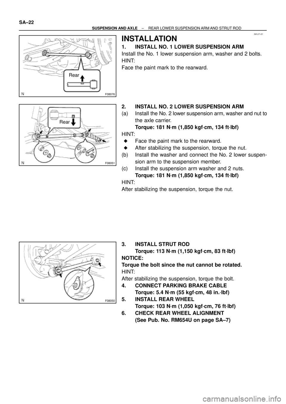
1. INSTALL NO. 1 LOWER SUSPENSION ARM
Install the No. 1 lower suspension arm, washer and 2 bolts.
HINT:
Face the paint mark to the rearward.
2. INSTALL NO. 2 LOWER SUSPENSION ARM
(a) Install the No. 2 lower suspension arm, washer and nut to
the axle carrier.
Torque: 181 N´m (1,850 kgf´cm, 134 ft´lbf)
HINT:
�Face the paint mark to the rearward.
�After stabilizing the suspension, torque the nut.
(b) Install the washer and connect the No. 2 lower suspen-
sion arm to the suspension member.
(c) Install the suspension arm washer and 2 nuts.
Torque: 181 N´m (1,850 kgf´cm, 134 ft´lbf)
HINT:
After stabilizing the suspension, torque the nut.
3. INSTALL STRUT ROD
Torque: 113 N´m (1,150 kgf´cm, 83 ft´lbf)
NOTICE:
Torque the bolt since the nut cannot be rotated.
HINT:
After stabilizing the suspension, torque the bolt.
4. CONNECT PARKING BRAKE CABLE
Torque: 5.4 N´m (55 kgf´cm, 48 in.´lbf)
5. INSTALL REAR WHEEL
Torque: 103 N´m (1,050 kgf´cm, 76 ft´lbf)
6. CHECK REAR WHEEL ALIGNMENT
(See Pub. No. RM654U on page SA±7)
Page 3651 of 4592
SA1FB±02
F08077
N´m (kgf´cm, ft´lbf) : Specified torque
Non±reusable part �
Bushing
Stabilizer Bar Bracket Stabilizer Bar
Stabilizer Bar Link
19 (195, 14)19 (195, 14)
39 (400, 29)
39 (400, 29)
± SUSPENSION AND AXLEREAR STABILIZER BAR
SA±23
530 Author�: Date�:
REAR STABILIZER BAR
COMPONENTS
Page 3652 of 4592
F08048
SA08M±02
F08078
SA±24
± SUSPENSION AND AXLEREAR STABILIZER BAR
REMOVAL
1. REMOVE RIGHT AND LEFT STABILIZER BAR LINKS
(a) Remove the 2 nuts and link.
HINT:
If the ball joint turns together with the nut, use a hexagon (5 mm)
wrench to hold the stud.
(b) Employ the same manner described above to the other
side.
2. REMOVE RIGHT AND LEFT BRACKETS AND BUSH-
INGS
(a) Remove the 2 bolts, bracket and bushings.
(b) Employ the same manner described above to the other
side.
3. REMOVE STABILIZER BAR
Page 3653 of 4592
SA1FE±02
F08079
Bushing
Stopper
± SUSPENSION AND AXLEREAR STABILIZER BAR
SA±25
INSTALLATION
1. INSTALL STABILIZER BAR
2. INSTALL RIGHT AND LEFT BUSHINGS AND STABI-
LIZER BAR BRACKETS
Torque: 19 N´m (195 kgf´cm, 14 ft´lbf)
HINT:
Install the bushing to the outside of the bushing stopper on the
stabilizer bar.
3. INSTALL RIGHT AND LEFT STABILIZER BAR LINKS
Torque: 39 N´m (400 kgf´cm, 29 ft´lbf)
HINT:
If the ball joint turns together with the nut, use a hexagon (5 mm)
wrench to hold the stud.