Page 3944 of 4592

TSB
IntroductionTo prevent overheating of the transmission when towing a weight of more than 1,000
pounds, a transmission oil cooler should be installed. The transmission oil cooler and
required hardware for installation are available through normal parts supply.
Towing�Up to 2,000 pounds (with transmission cooler installed).
Capacity
Affected�1997 Camrys with A541E Automatic Transmissions.
Vehicles
Parts
Information
Warranty
Information
TRANSMISSION & CLUTCH
October 17, 1997
Title:
TRANSMISSION OIL COOLER INSTALLATION
Models:
'97 CAMRY WITH A541E ATM
Page 1 of 6
TC003±97
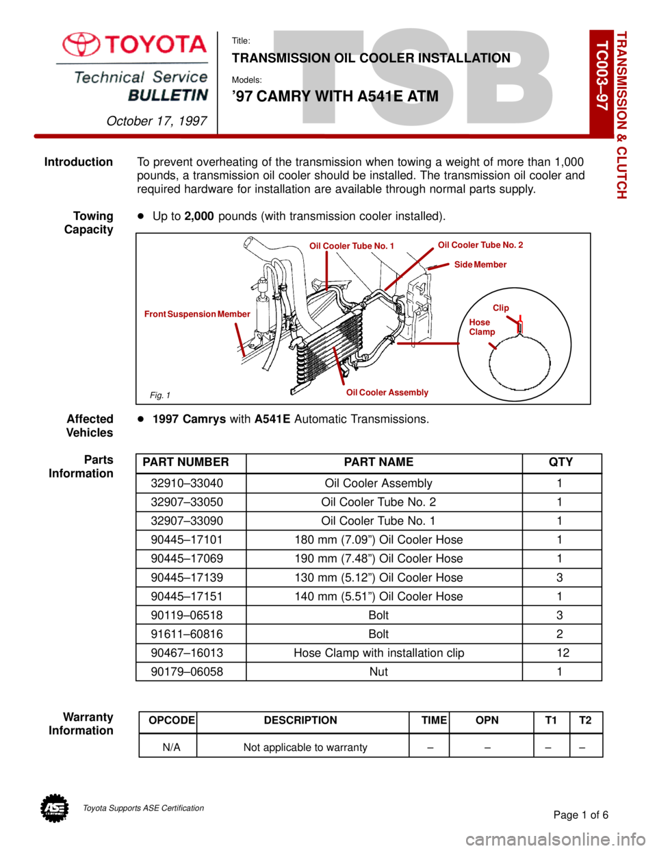
Clip
Hose
Clamp
Oil Cooler Assembly
Front Suspension Member
Oil Cooler Tube No. 1Oil Cooler Tube No. 2
Side Member
PART NUMBER PART NAME QTY
32910±33040 Oil Cooler Assembly 1
32907±33050 Oil Cooler Tube No. 2 1
32907±33090 Oil Cooler Tube No. 1 1
90445±17101 180 mm (7.09º) Oil Cooler Hose 1
90445±17069 190 mm (7.48º) Oil Cooler Hose 1
90445±17139 130 mm (5.12º) Oil Cooler Hose 3
90445±17151 140 mm (5.51º) Oil Cooler Hose 1
90119±06518 Bolt 3
91611±60816 Bolt 2
90467±16013 Hose Clamp with installation clip 12
90179±06058 Nut 1
OPCODE DESCRIPTION TIME OPN T1 T2
N/A Not applicable to warranty ± ± ± ±
Fig. 1
Toyota Supports ASE Certification
Page 3946 of 4592
Page 3 of 6
TRANSMISSION OIL COOLER INSTALLATION ± TC003±97 October 17, 1997
Procedure2. Cooler Installation:
(Continued)
A. Install the 140 mm (5.51º) hose to
the oil cooler tube No. 1 as shown.
NOTE:
Install the hose clamp with the hose
clamp clip at the position shown, and
use pliers to pull off the clip in the
direction indicated by the arrow.
B. Install the tube bracket onto the left
side of the front suspension
member with the 2 bolts as shown.
Torque: 62 in±lbf
(7 N±m / 71 kgf±cm)
C. Install the 130 mm (5.12º) hoses
and the 180 mm (7.09º) hose to the
oil cooler tube No. 2 as shown.
NOTE:
Install the hose clamps with the hose
clamp clips at the positions shown,
and use pliers to pull off the clips in
the direction indicated by the arrows.
Fig. 5
Oil Cooler Tube No. 1
140 mm Hose
5 mm (0.20º)
Fig. 6
Fig. 7
5 mm (0.20º)
180 mm Hose Oil Cooler Tube No. 2
130 mm Hose
Page 3947 of 4592

TRANSMISSION OIL COOLER INSTALLATION ± TC003±97 October 17, 1997
ProcedureD. Remove the lower side clip of the
(Continued) radiator side LH deflector.
E. Install the tube bracket with the bolt
on the side member.
Torque: 62 in±lbf
(7 N±m / 71 kgf±cm)
F. Reinstall the lower side clip
of the radiator LH deflector.
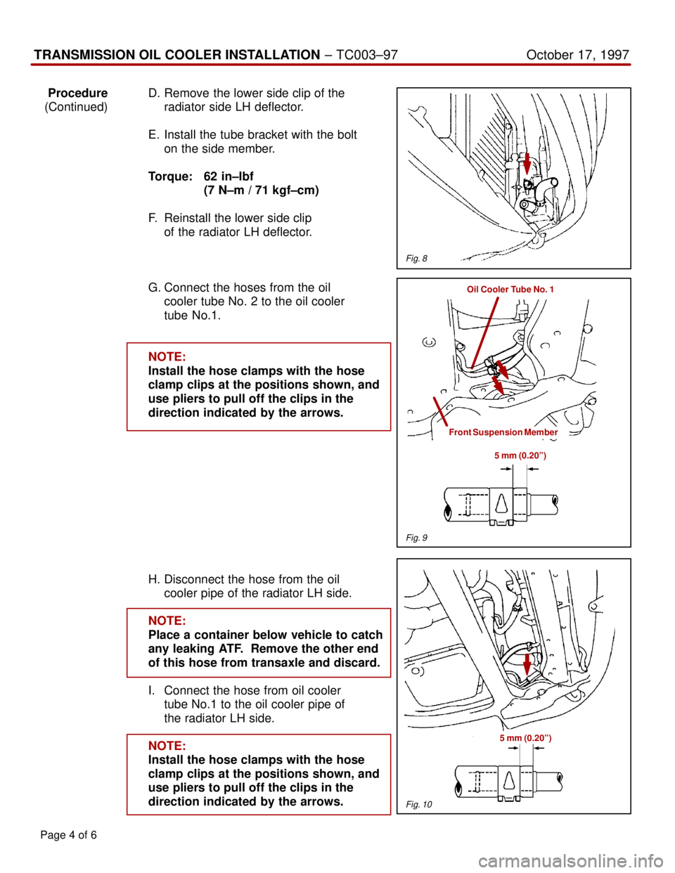
G. Connect the hoses from the oil
cooler tube No. 2 to the oil cooler
tube No.1.
NOTE:
Install the hose clamps with the hose
clamp clips at the positions shown, and
use pliers to pull off the clips in the
direction indicated by the arrows.
H. Disconnect the hose from the oil
cooler pipe of the radiator LH side.
NOTE:
Place a container below vehicle to catch
any leaking ATF. Remove the other end
of this hose from transaxle and discard.
I. Connect the hose from oil cooler
tube No.1 to the oil cooler pipe of
the radiator LH side.
NOTE:
Install the hose clamps with the hose
clamp clips at the positions shown, and
use pliers to pull off the clips in the
direction indicated by the arrows.
Page 4 of 6
Fig. 8
Oil Cooler Tube No. 1
Front Suspension Member
5 mm (0.20º)
Fig. 9
Fig. 10
5 mm (0.20º)