Page 3630 of 4592

F04031
F04048
1
2
F01195
Bolt
Adjusting
ValueSet Bolt
15'
30'Adjusting Bolt90105±15001 90105±15004 90105±15005 90105±15006
45'
1°00'
1°15'
1°30'121212121 Dot
2 Dots3 Dots SA±2
± SUSPENSION AND AXLEFRONT WHEEL ALIGNMENT
509 Author�: Date�:
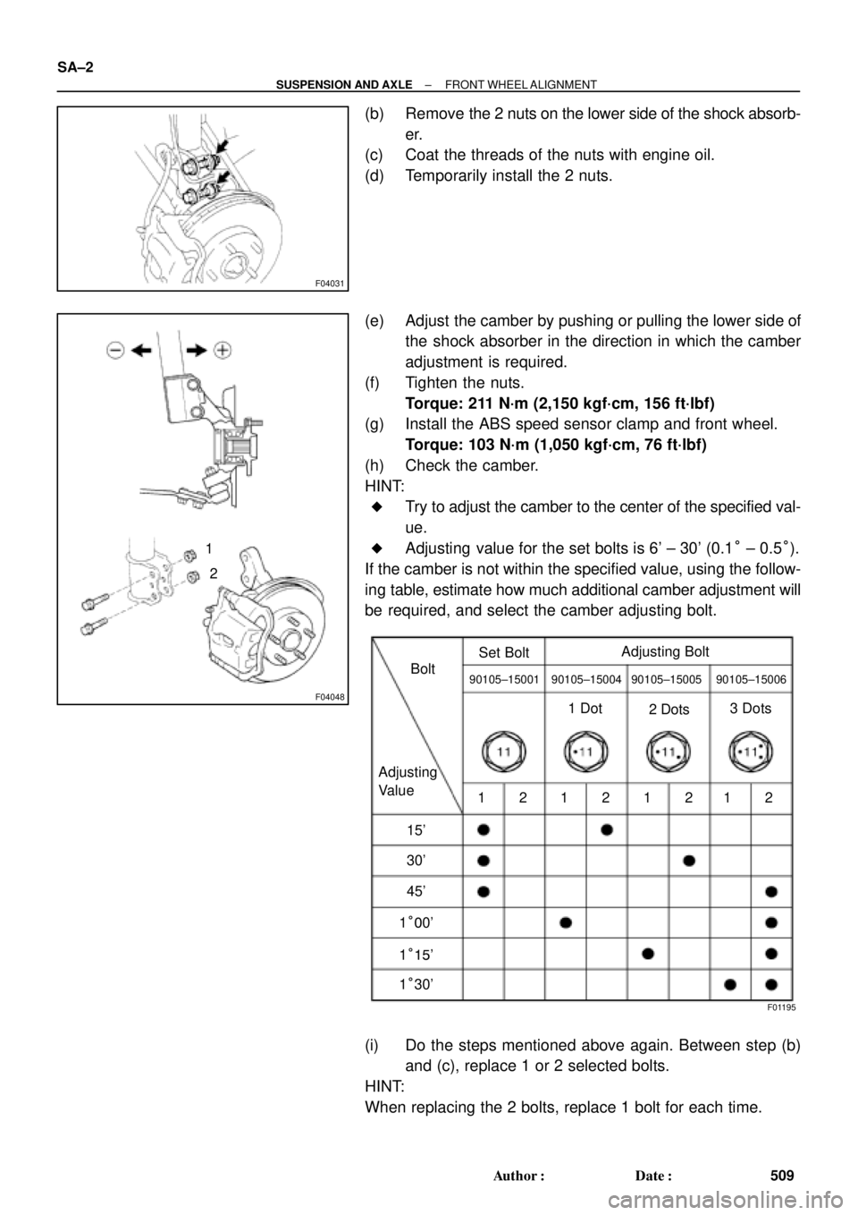
(b) Remove the 2 nuts on the lower side of the shock absorb-
er.
(c) Coat the threads of the nuts with engine oil.
(d) Temporarily install the 2 nuts.
(e) Adjust the camber by pushing or pulling the lower side of
the shock absorber in the direction in which the camber
adjustment is required.
(f) Tighten the nuts.
Torque: 211 N´m (2,150 kgf´cm, 156 ft´lbf)
(g) Install the ABS speed sensor clamp and front wheel.
Torque: 103 N´m (1,050 kgf´cm, 76 ft´lbf)
(h) Check the camber.
HINT:
�Try to adjust the camber to the center of the specified val-
ue.
�Adjusting value for the set bolts is 6' ± 30' (0.1° ± 0.5°).
If the camber is not within the specified value, using the follow-
ing table, estimate how much additional camber adjustment will
be required, and select the camber adjusting bolt.
(i) Do the steps mentioned above again. Between step (b)
and (c), replace 1 or 2 selected bolts.
HINT:
When replacing the 2 bolts, replace 1 bolt for each time.
Page 3631 of 4592

SA3213
Front A
DB
C
F02245
F02246
SA0028
Front AB
A B
A: Inside
B: Outside
± SUSPENSION AND AXLEFRONT WHEEL ALIGNMENT
SA±3
510 Author�: Date�:
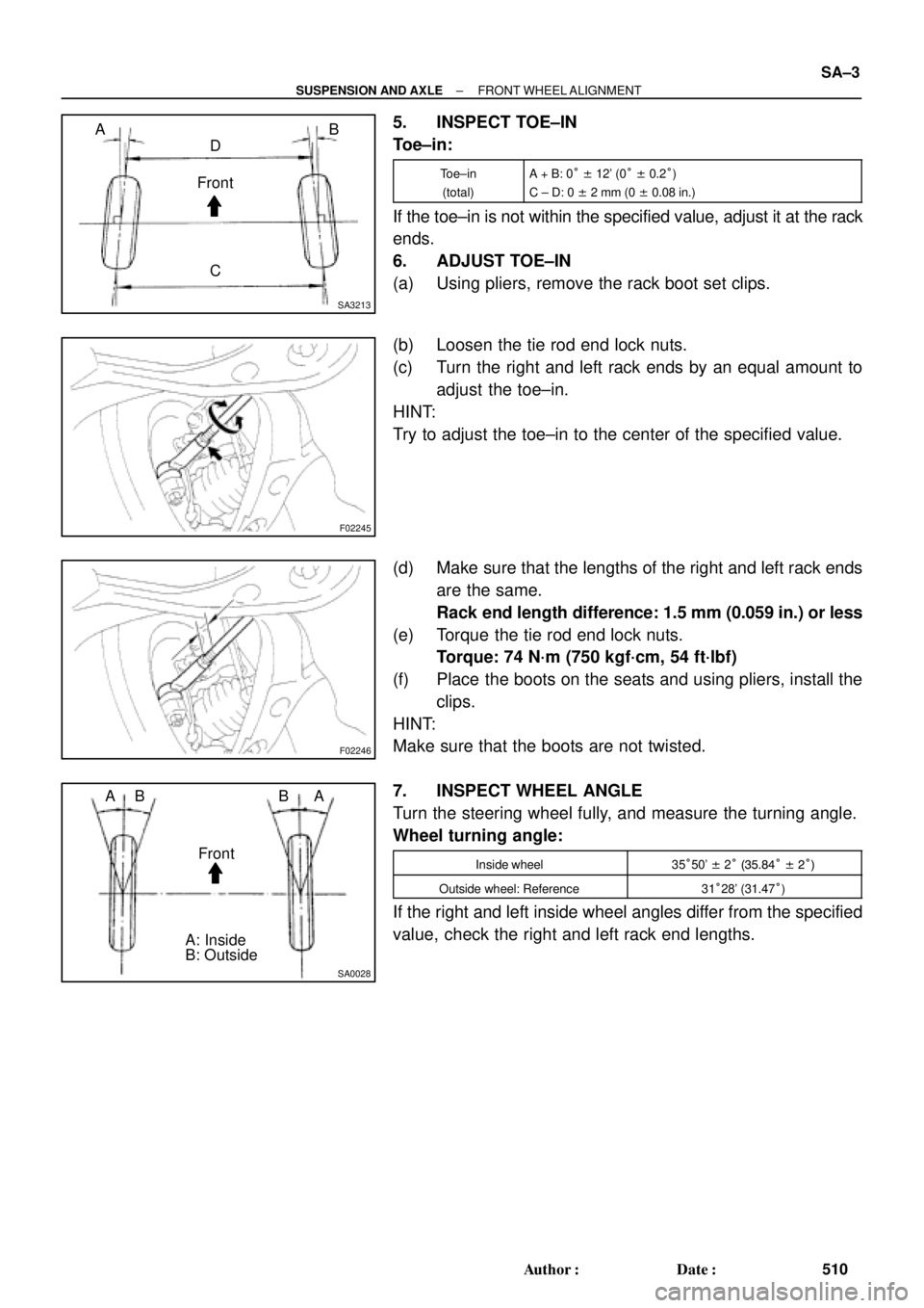
5. INSPECT TOE±IN
Toe±in:
Toe±in
(total)A + B: 0° ± 12' (0° ± 0.2°)
C ± D: 0 ± 2 mm (0 ± 0.08 in.)
If the toe±in is not within the specified value, adjust it at the rack
ends.
6. ADJUST TOE±IN
(a) Using pliers, remove the rack boot set clips.
(b) Loosen the tie rod end lock nuts.
(c) Turn the right and left rack ends by an equal amount to
adjust the toe±in.
HINT:
Try to adjust the toe±in to the center of the specified value.
(d) Make sure that the lengths of the right and left rack ends
are the same.
Rack end length difference: 1.5 mm (0.059 in.) or less
(e) Torque the tie rod end lock nuts.
Torque: 74 N´m (750 kgf´cm, 54 ft´lbf)
(f) Place the boots on the seats and using pliers, install the
clips.
HINT:
Make sure that the boots are not twisted.
7. INSPECT WHEEL ANGLE
Turn the steering wheel fully, and measure the turning angle.
Wheel turning angle:
Inside wheel35°50' ± 2° (35.84° ± 2°)
Outside wheel: Reference31°28' (31.47°)
If the right and left inside wheel angles differ from the specified
value, check the right and left rack end lengths.
Page 3632 of 4592
SA07B±05
F08042
Front Shock Absorber
Tie Rod End
Front Drive Shaft
Brake Caliper
ABS Speed Sensor
Lower Suspension ArmLock Cap
� Snap Ring
� Dust DeflectorSteering Knuckle
Dust Cover
�Bearing
Lower Ball JointAxle Hub � Cotter pin� Cotter pin� Cotter pin Hub Bolt
Disc
N´m (kgf´cm, ft´lbf) : Specified torque
� Non±reusable part
127 (1,300, 94)
107 (1,090, 79)
49 (500, 36)
8.3 (85, 74 in.´lbf)
123 (1,250, 90)
211 (2,150, 156)
294 (3,000, 217)
8.0 (82, 71 in.´lbf)
SA±4
± SUSPENSION AND AXLEFRONT AXLE HUB
511 Author�: Date�:
FRONT AXLE HUB
COMPONENTS
Page 3633 of 4592
SA08P±02
F03274
Fender Apron Seal
Drive Shaft (RH)
Fender Apron Seal �Lock Bolt
�Snap Ring
Tie Rod End
Lower
Suspension
Arm
� Boot Clamp
Outbord Joint Shaft � No. 2 Dust
Deflector�Snap RingDrive Shaft (LH)
�Snap Ring
�Snap Ring � Boot
� Boot� Cotter pin
Lock Cap
Tripod
� Dust Cover
� Center Bearing Inboard Joint Shaft Shaft Inboard Joint
� Dust Cover LH:
N´m (kgf´cm, ft´lbf): Specified torque
� Non±reusable part
32 (330, 24)
49 (500, 36)
294 (3,000, 217)
127 (1,300, 94)
RH:
± SUSPENSION AND AXLEFRONT DRIVE SHAFT
SA±5
512 Author�: Date�:
FRONT DRIVE SHAFT
COMPONENTS
Page 3634 of 4592

SA1JR±01
FA1535
SST
W03093
W03094
SST
W03095
SA±6
± SUSPENSION AND AXLEFRONT DRIVE SHAFT
REMOVAL
NOTICE:
�The hub bearing could be damaged if it is subjected
to the vehicle weight, such as when moving the ve-
hicle with the drive shaft removed.
Therefore, if it is absolutely necessary to place the ve-
hicle weight on the hub bearing, first support it with
SST.
SST 09608±16042 (09608±02021, 09608±02041)
�After disconnecting the drive shaft from the axle hub,
work carefully so as not to damage the ABS speed
sensor rotor serration on the drive shaft.
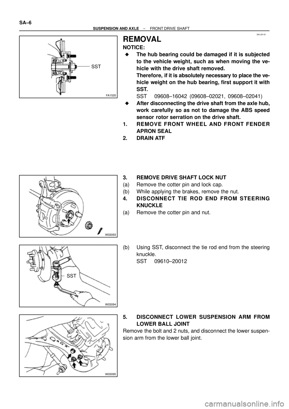
1. REMOVE FRONT WHEEL AND FRONT FENDER
APRON SEAL
2. DRAIN ATF
3. REMOVE DRIVE SHAFT LOCK NUT
(a) Remove the cotter pin and lock cap.
(b) While applying the brakes, remove the nut.
4. DISCONNECT TIE ROD END FROM STEERING
KNUCKLE
(a) Remove the cotter pin and nut.
(b) Using SST, disconnect the tie rod end from the steering
knuckle.
SST 09610±20012
5. DISCONNECT LOWER SUSPENSION ARM FROM
LOWER BALL JOINT
Remove the bolt and 2 nuts, and disconnect the lower suspen-
sion arm from the lower ball joint.
Page 3635 of 4592
W03142
R00647
LH:
W03144
RH:
± SUSPENSION AND AXLEFRONT DRIVE SHAFT
SA±7
6. DISCONNECT DRIVE SHAFT FROM AXLE HUB
(a) Using a plastic hammer, disconnect the drive shaft from
the axle hub.
NOTICE:
Be careful not to damage the boot and ABS speed sensor
rotor.
(b) Push the front axle hub toward the outside of the vehicle,
and separate the drive shaft from the axle hub.
7. REMOVE LH DRIVE SHAFT
(a) Using a hub nut wrench and wooden block or an equiva-
lent, remove the drive shaft.
(b) Using a screwdriver, remove the snap ring from the in-
board joint shaft.
NOTICE:
Be careful not to damage the boot and ABS speed sensor
rotor.
8. REMOVE RH DRIVE SHAFT
(a) Remove the bearing lock bolt.
(b) Using pliers, remove the snap ring and drive shaft.
NOTICE:
Be careful not to damage the boot and ABS speed sensor
rotor.
Page 3636 of 4592

SA1EA±02
N00191
F06526
BA
FA1615
Matchmarks
SA1443
Matchmarks
SA±8
± SUSPENSION AND AXLEFRONT DRIVE SHAFT
DISASSEMBLY
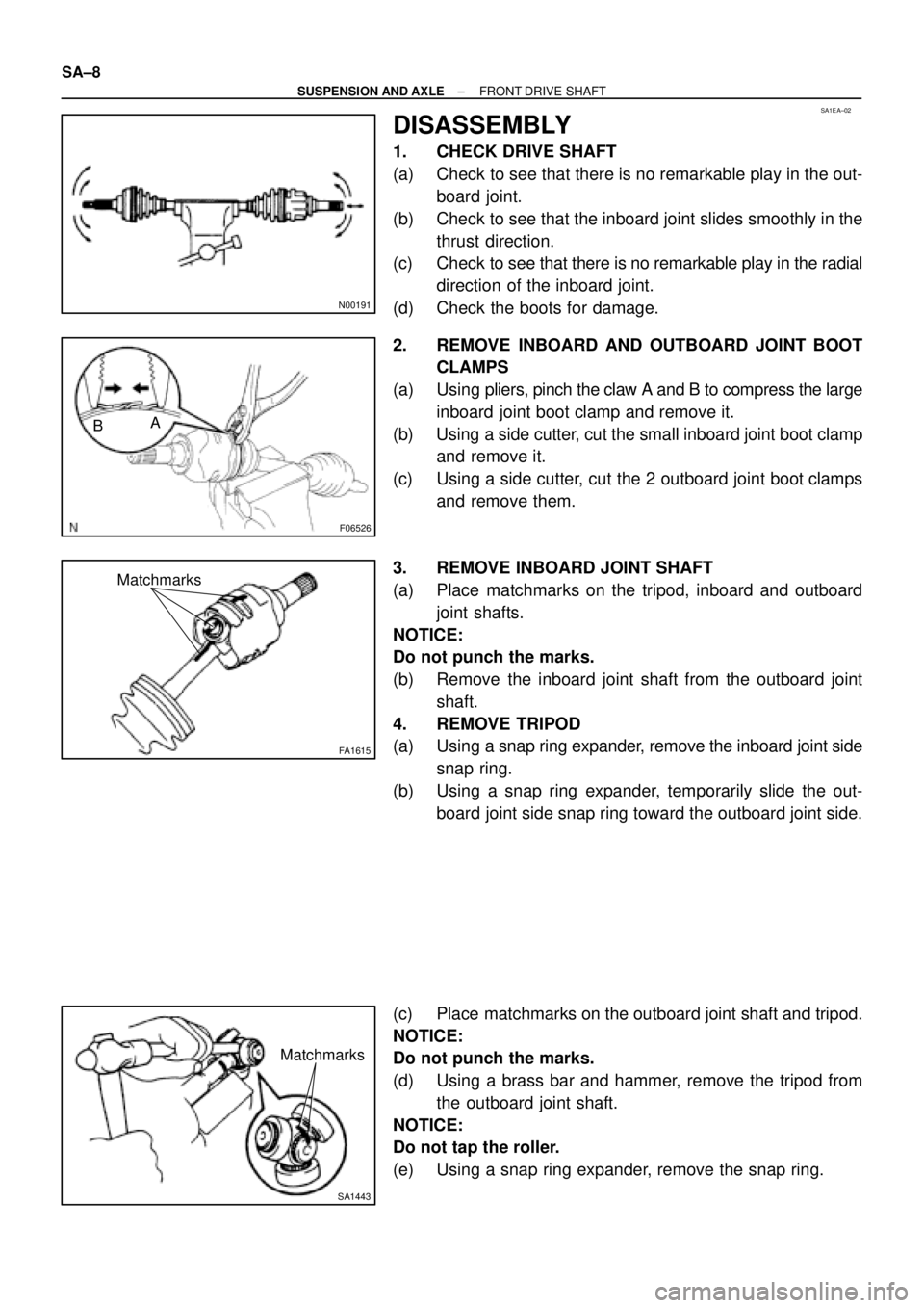
1. CHECK DRIVE SHAFT
(a) Check to see that there is no remarkable play in the out-
board joint.
(b) Check to see that the inboard joint slides smoothly in the
thrust direction.
(c) Check to see that there is no remarkable play in the radial
direction of the inboard joint.
(d) Check the boots for damage.
2. REMOVE INBOARD AND OUTBOARD JOINT BOOT
CLAMPS
(a) Using pliers, pinch the claw A and B to compress the large
inboard joint boot clamp and remove it.
(b) Using a side cutter, cut the small inboard joint boot clamp
and remove it.
(c) Using a side cutter, cut the 2 outboard joint boot clamps
and remove them.
3. REMOVE INBOARD JOINT SHAFT
(a) Place matchmarks on the tripod, inboard and outboard
joint shafts.
NOTICE:
Do not punch the marks.
(b) Remove the inboard joint shaft from the outboard joint
shaft.
4. REMOVE TRIPOD
(a) Using a snap ring expander, remove the inboard joint side
snap ring.
(b) Using a snap ring expander, temporarily slide the out-
board joint side snap ring toward the outboard joint side.
(c) Place matchmarks on the outboard joint shaft and tripod.
NOTICE:
Do not punch the marks.
(d) Using a brass bar and hammer, remove the tripod from
the outboard joint shaft.
NOTICE:
Do not tap the roller.
(e) Using a snap ring expander, remove the snap ring.
Page 3637 of 4592
R09716
SST
SA1446
R09717
SST
SA1451
± SUSPENSION AND AXLEFRONT DRIVE SHAFT
SA±9
5. REMOVE INBOARD AND OUTBOARD JOINT BOOTS
Slide out the 2 boots.
NOTICE:
Do not disassemble the outboard joint.
6. LH drive shaft:
REMOVE DUST COVER
Using SST and a press, remove the dust cover from the inboard
joint shaft.
SST 09950±00020
7. RH drive shaft:
DISASSEMBLE INBOARD JOINT SHAFT
(a) Using a press, remove the transaxle side dust cover from
the inboard joint shaft.
(b) Using SST and a press, remove the bearing side dust
cover.
SST 09950±00020
(c) Using a snap ring expander, remove the snap ring.
(d) Using a press, remove the bearing.
(e) Remove the snap ring.