Page 3099 of 4592
PP0KJ±01
PP±74
± PREPARATIONAUTOMATIC TRANSAXLE (A140E)
126 Author�: Date�:
LUBRICANT
ItemCapacityClassification
Automatic transaxle
Dry fill
Drain and refill
5.6 liters (5.9 US qts, 4.9 Imp.qts)
2.5 liters (2.6 US qts, 2.2 Imp.qts)ATF D±II or DEXRON®III (DEXRON®II)
Differential oil1.6 liters (1.7 US qts, 1.4 Imp.qts)ATF D±II or DEXRON®III (DEXRON®II)
Page 3103 of 4592
PP0M4±01
PP±78
± PREPARATIONAUTOMATIC TRANSAXLE (A541E)
130 Author�: Date�:
LUBRICANT
ItemCapacityClassification
Automatic transaxle fluid
(w/o Differential oil)
Dry fill
Drain and refill
8.0 liters (8.5 US qts, 7.0 Imp. qts)
3.9 liters (4.1 US qts, 3.4 Imp. qts)ATF D±II or DEXRON®III (DEXRON®II)
Page 3171 of 4592

AB0158
SSTBattery
AB0152
SST
AB0158
SSTBattery
H01580
SST
W03515
± SUPPLEMENTAL RESTRAINT SYSTEMSTEERING WHEEL PAD AND SPIRAL CABLE
RS±19
2164 Author�: Date�:
1. AIRBAG DEPLOYMENT WHEN SCRAPPING VE-
HICLE
HINT:
Have a battery ready as the power source to deploy the airbag.
(a) Check functioning of the SST.
CAUTION:
When deploying the airbag, always use the specified SST:
SRS Airbag Deployment Tool.
SST 09082±00700
(1) Connect the SST to the battery.
Connect the red clip of the SST to the battery posi-
tive (+) terminal and the black clip to the battery neg-
ative (±) terminal.
HINT:
Do not connect the yellow connector which will be connected
with the supplemental restraint system.
(2) Check functioning of the SST.
Press the SST activation switch, and check that the
LED of the SST activation switch lights up.
CAUTION:
If the LED lights up when the activation switch is not being
pressed, SST malfunction is probable, so definitely do not
use the SST.
(b) Install the SST.
CAUTION:
Check that there is no looseness in the steering wheel and
steering wheel pad.
(1) Remove the steering column lower cover.
Remove the 3 screws and steering column lower
cover as shown in the illustration.
(2) Disconnect the airbag connector of the spiral cable.
Page 3328 of 4592
FUEL PUMP
1439 Author�: Date�:
FUEL PUMP
ON±VEHICLE INSPECTION
1. CHECK FUEL PUMP OPERATION
(a) Connect a TOYOTA hand±held tester")
S05331
SF0D7±03
S05327
Fuel Inlet Hose
S05522
SF±6
± SFI (5S±FE)FUEL PUMP
1439 Author�: Date�:
FUEL PUMP
ON±VEHICLE INSPECTION
1. CHECK FUEL PUMP OPERATION
(a) Connect a TOYOTA hand±held tester to the DLC3.
(b) Turn the ignition switch ON and push the TOYOTA hand±
held tester main switch ON.
NOTICE:
Do not start the engine.
(c) Select the ACTIVE TEST mode on the TOYOTA hand±
held tester.
(d) Please refer to the TOYOTA hand±held tester operator's
manual for further details.
(e) If you have no TOYOTA hand±held tester, connect the
positive (+) and negative (±) leads from the battery to the
fuel pump connector. (See step 7)
(f) Check that there is pressure in the fuel inlet hose from the
fuel filter.
HINT:
If there is fuel pressure, you will hear the sound of fuel flowing.
If there is no pressure, check the fusible link, fuses, EFI main
relay, fuel pump, ECM and wiring connections.
(g) Turn the ignition switch OFF.
(h) Disconnect the TOYOTA hand±held tester from the
DLC3.
2. CHECK FUEL PRESSURE
(a) Check the battery positive voltage is above 12 V.
(b) Disconnect the negative (±) terminal cable from the bat-
tery.
(c) Remove the union bolt and 2 gaskets, and disconnect the
fuel inlet hose from the fuel filter outlet.
CAUTION:
�Put a shop towel under the fuel filter.
�Slowly loosen the union bolt.
Page 3362 of 4592
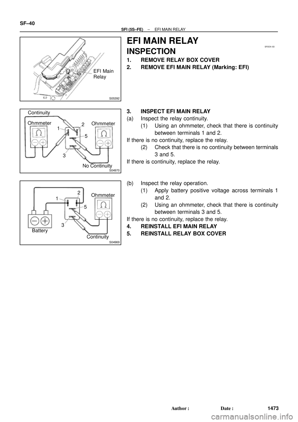
S05392
EFI Main
Relay
SF0DX±03
S04970
Continuity
No ContinuityOhmmeter
2
35 Ohmmeter
1
S04969ContinuityOhmmeter 2
35 1
Battery SF±40
± SFI (5S±FE)EFI MAIN RELAY
1473 Author�: Date�:
EFI MAIN RELAY
INSPECTION
1. REMOVE RELAY BOX COVER
2. REMOVE EFI MAIN RELAY (Marking: EFI)
3. INSPECT EFI MAIN RELAY
(a) Inspect the relay continuity.
(1) Using an ohmmeter, check that there is continuity
between terminals 1 and 2.
If there is no continuity, replace the relay.
(2) Check that there is no continuity between terminals
3 and 5.
If there is continuity, replace the relay.
(b) Inspect the relay operation.
(1) Apply battery positive voltage across terminals 1
and 2.
(2) Using an ohmmeter, check that there is continuity
between terminals 3 and 5.
If there is no continuity, replace the relay.
4. REINSTALL EFI MAIN RELAY
5. REINSTALL RELAY BOX COVER
Page 3371 of 4592
SF0E6±03
S01196S01699Z17274
Ohmmeter
Resistance kW
Temperature °C (°F) Acceptable 30
20
10
5
3
2
1
0.5
0.3
0.2
0.1
40 ±20 0 20 60 80 100
(212) (176) (140) (104) (68) (32) (±4)
± SFI (5S±FE)ENGINE COOLANT TEMPERATURE (ECT) SENSOR
SF±49
1482 Author�: Date�:
INSPECTION
1. DRAIN ENGINE COOLANT
2. REMOVE ECT SENSOR
3. INSPECT ECT SENSOR
Using an ohmmeter, measure the resistance between the ter-
minals.
Resistance: Refer to the graph
If the resistance is not as specified, replace the ECT sensor.
4. REINSTALL ECT SENSOR
5. REFILL WITH ENGINE COOLANT
Page 3394 of 4592
FUEL PUMP
1505 Author�: Date�:
FUEL PUMP
ON±VEHICLE INSPECTION
1. CHECK FUEL PUMP OPERATION
(a) Connect")
S05358
TOYOTA
Hand Held TesterSF079±04
S05353
S05359
Fuel Tube Connector
SF±6
± SFI (1MZ±FE)FUEL PUMP
1505 Author�: Date�:
FUEL PUMP
ON±VEHICLE INSPECTION
1. CHECK FUEL PUMP OPERATION
(a) Connect a TOYOTA hand±held tester to the DLC3.
(b) Turn the ignition switch ON and push the TOYOTA hand±
held tester main switch ON.
NOTICE:
Do not start the engine.
(c) Select the ACTIVE TEST mode on the TOYOTA hand±
held tester.
(d) Please refer to the TOYOTA hand±held tester operator's
manual for further details.
(e) If you have no TOYOTA hand±held tester, connect the
positive (+) and negative (±) leads from the battery to the
fuel pump connector. (See step 7)
(f) Check that there is pressure in the fuel inlet hose from the
fuel filter.
HINT:
If there is fuel pressure, you will hear the sound of fuel flowing.
If there is no pressure, check these parts:
Fusible link
Fuses
EFI main relay
Fuel pump
ECM
Wiring connections
(g) Turn the ignition switch OFF.
(h) Disconnect the TOYOTA hand±held tester from the
DLC3.
2. CHECK FUEL PRESSURE
(a) Check the battery positive voltage is above 12 V.
(b) Disconnect the negative (±) terminal cable from the bat-
tery.
(c) Purchase the new No.1 fuel pipe and take out the fuel
tube connector from its pipe.
Part No. 23801±20041
Page 3441 of 4592
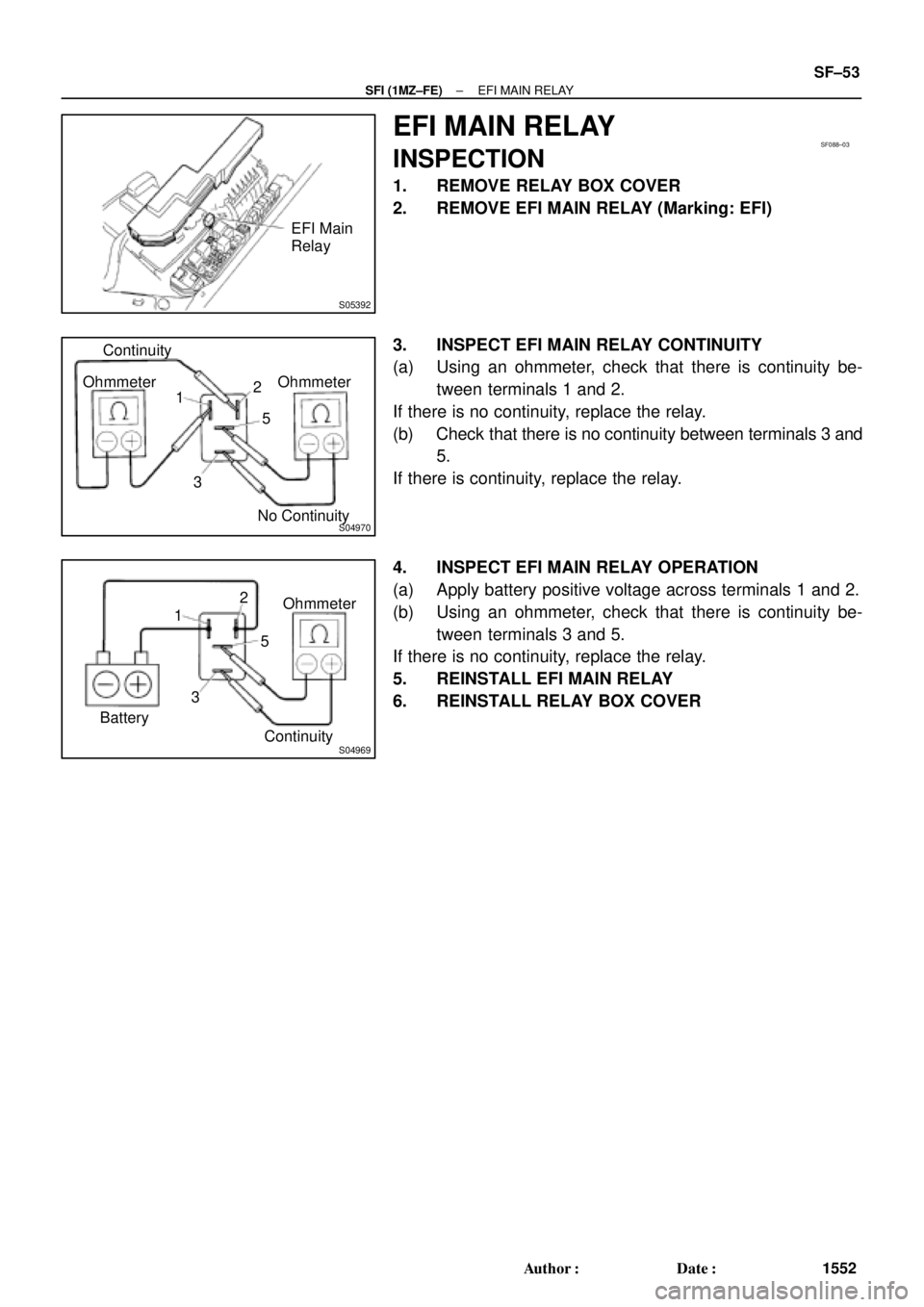
S05392
EFI Main
Relay
SF088±03
S04970
Ohmmeter OhmmeterContinuity
No Continuity 12
5
3
S04969
Ohmmeter
Continuity 12
5
3
Battery
± SFI (1MZ±FE)EFI MAIN RELAY
SF±53
1552 Author�: Date�:
EFI MAIN RELAY
INSPECTION
1. REMOVE RELAY BOX COVER
2. REMOVE EFI MAIN RELAY (Marking: EFI)
3. INSPECT EFI MAIN RELAY CONTINUITY
(a) Using an ohmmeter, check that there is continuity be-
tween terminals 1 and 2.
If there is no continuity, replace the relay.
(b) Check that there is no continuity between terminals 3 and
5.
If there is continuity, replace the relay.
4. INSPECT EFI MAIN RELAY OPERATION
(a) Apply battery positive voltage across terminals 1 and 2.
(b) Using an ohmmeter, check that there is continuity be-
tween terminals 3 and 5.
If there is no continuity, replace the relay.
5. REINSTALL EFI MAIN RELAY
6. REINSTALL RELAY BOX COVER


 Acceptable 30
20
10
5
3
2
1
0.5
0.3
0.2
0.1
40 ±20 0 20 60 80 100
(212) (176) (140) (104) (68) (32) (±4)
± SFI (5S±FE)ENGI")