1999 TOYOTA CAMRY efi
[x] Cancel search: efiPage 3857 of 4592
Toyota Supports ASE CertificationPage 1 of 1
PG001±00
Title:
2000 TECHNICAL SERVICE BULLETIN
INFORMATION
Models:
All Models
Technical Service
BULLETIN
January 7, 2000
Toyota Technical Service Bulletins (TSBs) continue to be one of the most current sources
of technical information available. To ensure complete access to this reference source,
use the following steps:
�All 1999 Technical Service Bulletins should be relocated to a temporary binder.
�Place this bulletin along with all 2000 TSBs into the emptied TSB binder.
�During the month of March, all dealers will receive bound books containing all TSBs
issued in 1999. Upon receipt, discard all 1999 TSBs and refer only to the bound
book for reference.
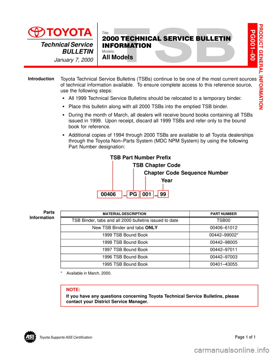
�Additional copies of 1994 through 2000 TSBs are available to all Toyota dealerships
through the Toyota Non±Parts System (MDC NPM System) by using the following
Part Number designation:
00406PG00199
TSB Part Number Prefix
TSB Chapter Code
Chapter Code Sequence Number
Year
±±
MATERIAL DESCRIPTIONPART NUMBER
TSB Binder, tabs and all 2000 bulletins issued to dateTSB00
New TSB Binder and tabs ONLY00406±61012
1999 TSB Bound Book00442±99002*
1998 TSB Bound Book00442±98005
1997 TSB Bound Book00442±97011
1996 TSB Bound Book00442±97003
1995 TSB Bound Book00401±43055
* Available in March, 2000.
NOTE:
If you have any questions concerning Toyota Technical Service Bulletins, please
contact your District Service Manager.
PRODUCT GENERAL INFORMATION
Introduction
Parts
Information
Page 3883 of 4592
Toyota Supports ASE CertificationPage 1 of 3
PG006±03
Title:
WARRANTY PARTS
MARKING PROCEDURE
Models:
All Models
Technical Service
BULLETIN
September 26, 2003
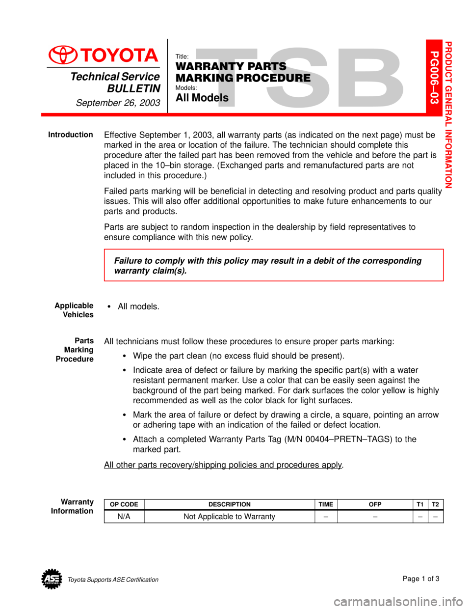
Effective September 1, 2003, all warranty parts (as indicated on the next page) must be
marked in the area or location of the failure. The technician should complete this
procedure after the failed part has been removed from the vehicle and before the part is
placed in the 10±bin storage. (Exchanged parts and remanufactured parts are not
included in this procedure.)
Failed parts marking will be beneficial in detecting and resolving product and parts quality
issues. This will also offer additional opportunities to make future enhancements to our
parts and products.
Parts are subject to random inspection in the dealership by field representatives to
ensure compliance with this new policy.
Failure to comply with this policy may result in a debit of the corresponding
warranty claim(s).
�All models.
All technicians must follow these procedures to ensure proper parts marking:
�Wipe the part clean (no excess fluid should be present).
�Indicate area of defect or failure by marking the specific part(s) with a water
resistant permanent marker. Use a color that can be easily seen against the
background of the part being marked. For dark surfaces the color yellow is highly
recommended as well as the color black for light surfaces.
�Mark the area of failure or defect by drawing a circle, a square, pointing an arrow
or adhering tape with an indication of the failed or defect location.
�Attach a completed Warranty Parts Tag (M/N 00404±PRETN±TAGS) to the
marked part.
All other parts recovery/shipping policies and procedures apply
.
OP CODEDESCRIPTIONTIMEOFPT1T2
N/ANot Applicable to Warranty±±±±
PRODUCT GENERAL INFORMATION
Introduction
Applicable
Vehicles
Parts
Marking
Procedure
Warranty
Information
Page 4011 of 4592

A INTRODUCTION
This manual consists of the following 13 sections:
No.
SectionDescription
A
INDEXIndex of the contents of this manual.
A
INTRODUCTIONBrief explanation of each section.
BHOW TO USE THIS
MANUALInstructions on how to use this manual.
CTROUBLE±
SHOOTINGDescribes the basic inspection procedures for electrical circuits.
DABBREVIATIONSDefines the abbreviations used in this manual.
E
GLOSSARY OF
TERMS AND
SYMBOLS
Defines the symbols and functions of major parts.
FRELAY LOCATIONSShows position of the Electronic Control Unit, Relays, Relay Block, etc.
This section is closely related to the system circuit.
GELECTRICAL
WIRING ROUTINGDescribes position of Parts Connectors, Splice points, Ground points, etc.
This section is closely related to the system circuit.
INDEXIndex of the system circuits.
H
SYSTEM CIRCUITS
Electrical circuits of each system are shown from the power supply through ground
points. Wiring connections and their positions are shown and classified by code
according to the connection method. (Refer to the section, ºHow to use this manualº).
The ºSystem Outlineº and ºService Hintsº useful for troubleshooting are also contained
in this section.
IGROUND POINTShows ground positions of all parts described in this manual.
JPOWER SOURCE
(Current Flow Chart)Describes power distribution from the power supply to various electrical loads.
KCONNECTOR LISTDescribes the form of the connectors for the parts appeared in this book.
This section is closely related to the system circuit.
LPART NUMBER OF
CONNECTORSIndicates the part number of the connectors used in this manual.
M
OVERALL
ELECTRICAL
WIRING DIAGRAM
Provides circuit diagrams showing the circuit connections.
Page 4018 of 4592
B
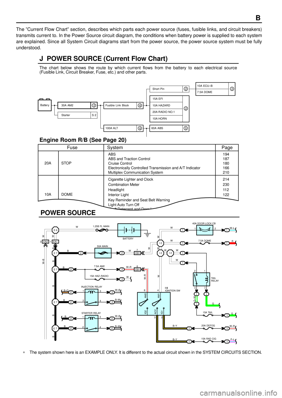
The ºCurrent Flow Chartº section, describes which parts each power source (fuses, fusible links, and circuit breakers)
transmits current to. In the Power Source circuit diagram, the conditions when battery power is supplied to each system
are explained. Since all System Circuit diagrams start from the power source, the power source system must be fully
understood.
Theft Deterrent and Door Lock Control
J POWER SOURCE (Current Flow Chart)
11
1
EA1 1EA2 3
7
EB16
E 6
E 7I 2I 2
I 2
E 7
E 7
E 7
2
1
1
2
2
2
2
2
B
B
W W
B B B B BW±B
B
B
B B±O
B±W
W±B
B±W STARTER RELAY INJECTION RELAY15A HAZ±RADIO7.5A AM250A MAIN 1.25B FL MAIN
BATTERY
WWW
W W W
R W±L
W
W
G±W
G
15A TAIL
20A DEFOG
15A RAD CIGTA I L
RELAY 7.5A DOME 40A DOOR LOCK CB
2 1
1 2
4 8
2 3
3 4
G
W±R
P±L B±Y
B±Y
W±R
AM2 IG2
ACC
IG1AM1W W
W±R
W W
W±B
21
1
1
1
1
2
2
2
2
3
4
3
4 1
2
1
22
1
11
1
IGNITION SW I 8
Battery
30A AM2
2
Starter S 220A RADIO NO.1
10A HORN
15A EFI
7.5A DOMEShort Pin
10A HAZARD
The chart below shows the route by which current flows from the battery to each electrical source
(Fusible Link, Circuit Breaker, Fuse, etc.) and other parts.
Engine Room R/B (See Page 20)
ABS
ABS and Traction Control
Cruise Control
Electronically Controlled Transmission and A/T Indicator
Multiplex Communication System
Cigarette Lighter and Clock
Key Reminder and Seat Belt Warning STOP
Fuse Page
194
214
11 2
System
DOME 20A
10ACombination Meter
Headlight
Interior Light
2
2
6 100A ALT
EB1
POWER SOURCE
Light Auto Turn Off187
180
166
210
230
122
10A ECU±B
5 60A ABS
2
6 Fusible Link Block2
*The system shown here is an EXAMPLE ONLY. It is different to the actual circuit shown in the SYSTEM CIRCUITS SECTION.
Page 4051 of 4592
POWER SOURCE
1260A FL ABS
3
1
1
2B2
2A1
2B3
1240A MAIN
EB B 1F1F2E1
A 1C1D1 E 31
1
1
2L4
2G3
2G4 2C5
2K6 1
4
1
3
4
1
3
1
4 2
5
2
5
2
3 B
B
BB±R L±WL±B L±R
L±B W±B B±G
B±R
W±B
W±R
B±G
B±R B±R
B±R
L±B
W±B
W±B
W±B R±B
BATTERY
FL MAIN 3. 0W
100A
ALT50A
HTR GENERATOR G 2
HTR RELAY
ENGINE MAIN RELAY
20A EFI
10A HAZARD
20A RADIO NO. 1
10A HORN
30A AM2
SHORT PIN
5A ALT±S
HEAD RELAY
15A HEAD (
RH)
15A HEAD (
LH)30A CDS30A RDI
10A ECU±B
7. 5A DOME 112
1
10A A/C
2F4
W±B
B±R
12L±R
F 9 BA, F10
F12
FUSIBLE LINK BLOCKE D, F13C , F11
F , F14, B±G
1
12
2
Page 4061 of 4592
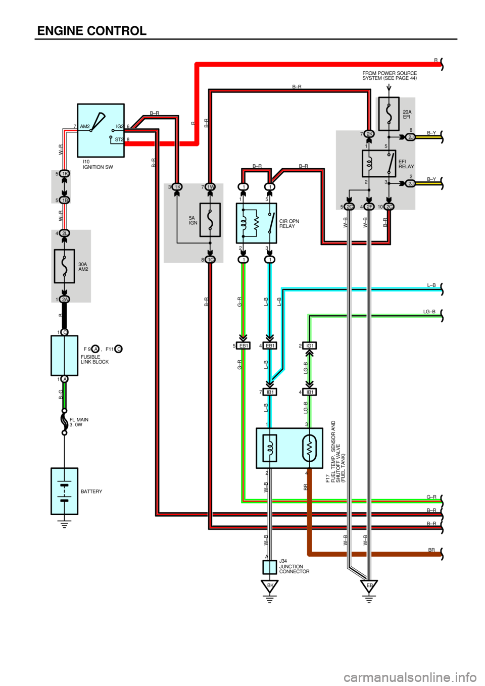
ENGINE CONTROL
11
11 23 15
CIR OPN
RELAY 5A
IGN
30A
AM2 1K 5
2L 41K 31W7
1C 8 1B 5
2A 1
BK IB 1 7EB1 4 EB1 5 C 1
A 176
8 AM2 IG2
ST2B±R
L±B L±B L±B W±B W±BG± RB±RB±R W±R W±R B B±G
23 1520A
EFI FROM POWER SOURCE
SYSTEM (
SEE PAGE 44)
EB2K 7
2F 42C10
W±B W±B
IGNITION SW I10
BATTERY FL MAIN
3. 0WEFI
RELAY
JUNCTION
CONNECTOR J34 A
G±R
2J8
2J2
B±R
FUSIBLE
LINK BLOCK2C 5
W±B
B±R
IG1 2
IB1 4
13
24 B±R
FUEL TEMP. SENSOR AND
SHUTOFF VALVE
(
FUEL TANK) F1 7
R
B±Y
L±B
LG±B
G± R
B±R
B±R
BR B±Y
LG±B LG±B
C F 9 A , F11
BR
W±B
B±R
B±R
L±BR
Page 4068 of 4592

This system utilizes an engine control module and maintains overall control of the engine, transmission and so on. An outline
of the engine control is explained here.
1. INPUT SIGNALS
(1) Engine coolant temp. signal circuit
The engine coolant temp. sensor detects the engine coolant temp. and has a built±in thermistor with a resistance which
varies according to the engine coolant temp. thus the engine coolant temp. is input in the form of a control signal into
TERMINAL THW of the engine control module.
(2) Intake air temp. signal circuit
The intake air temp. sensor detects the intake air temp. , which is input as a control signal into TERMINAL THA of the
engine control module.
(3) Oxygen sensor signal circuit
The oxygen density in the exhaust gases is detected and input as a control signal into TERMINAL OX2 of the engine
control module.
(4) RPM signal circuit
Camshaft position and crankshaft position are detected by the camshaft position sensor and crankshaft position sensor.
Camshaft position is input as a control signal to TERMINAL G of the engine control module, and engine RPM is input
into TERMINAL NE.
(5) Throttle signal circuit
The throttle position sensor detects the throttle valve opening angle, which is input as a control signal into TERMINAL
VTA of the engine control module.
(6) Vehicle speed signal circuit
The vehicle speed sensor, installed inside the transmission, detects the vehicle speed and inputs a control signal into
TERMINAL SPD of the engine control module.
(7) Park/Neutral position SW signal circuit
The Park/Neutral position SW detects whether the shift position are in neutral, parking or not, and inputs a control signal
into TERMINAL STA of the engine control module.
(8) A/C SW signal circuit
The A/C amplifier is built in the engine control module. The signal from the A/C SW is input into TERMINAL A/CS of the
engine control module.
(9) Battery signal circuit
Voltage is constantly applied to TERMINAL BATT of the engine control module. When the ignition SW is turned on, the
voltage for engine control module start±up power supply is applied to TERMINAL +B of engine control module via EFI
relay.
(10) Intake air volume signal circuit
Intake air volume is detected by the manifold absolute pressure sensor (for manifold pressure) and is input as a control
signal into TERMINAL PIM of the engine control module.
(11) Starter signal circuit
To confirm whether the engine is cranking, the voltage applied to the starter motor during cranking is detected and the
signal is input into TERMINAL NSW of the engine control module as a control signal.
(12) Electrical load signal circuit
The signal when systems such as the rear window defogger, headlights, etc. Which cause a high electrical burden are
on is input to TERMINAL ELS as a control signal.
(13) Air fuel ratio signal circuit
The air fuel ratio is detected and input as a control signal into TERMINAL AF+ of the engine control module.
SYSTEM OUTLINE
Page 4109 of 4592
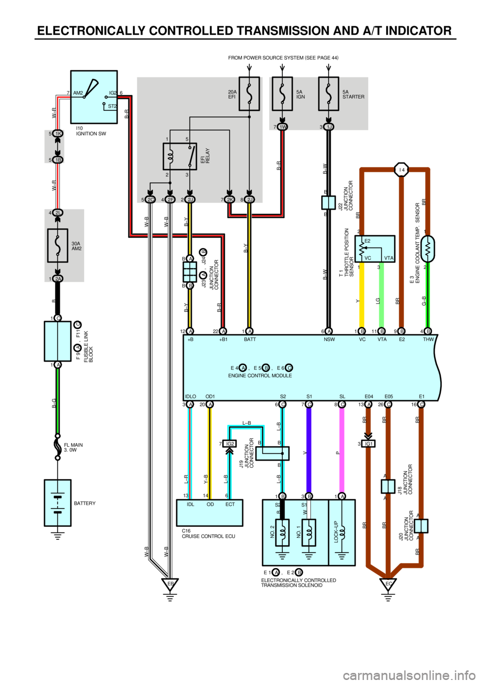
ELECTRONICALLY CONTROLLED TRANSMISSION AND A/T INDICATOR
72K
NO. 2
LOCK±UPNO. 1
B E 1
ELECTRONICALLY CONTROLLED
TRANSMISSION SOLENOIDAB 20A
EFI FROM POWER SOURCE SYSTEM (
SEE PAGE 44)
2J 8 3 15
2F 42J2
1 2
2 1
A 1B1B11 B4 B 9
C 6C7C8C16 A B
B B
EBEC B
A B3
A
B±YB±Y W±B W± B
BR
BR G±BLGY
BR L±B L±B
V
P
BR BREFI
RELAY
E 2
THROTTLE POSITION
SENSOR
ENGINE COOLANT TEMP. SENSORT 1
E 3 B
W
S2 S1 IG2 7 A 3A20
CRUISE CONTROL ECU C166 13 14
L±B L±R
Y±B
ECT IDL ODB ENGINE CONTROL MODULEB AC A 12
B±Y
B±R
JUNCTION
CONNECTOR J20JUNCTION
CONNECTOR J19
L±B5A
IGN
1W 7
1A 3B 1B
, E 4 , E 5 , E 6
J23
JUNCTION
CONNECTORB A, J24
A 65A
STARTER
1J 3
B±W B±W
JUNCTION
CONNECTOR J22
C 26
BR
B 2C 5
W±B
VC E2
VTA
+B BATT NSW VC VTA E2 THW
IDLO OD1 S2 S1 SL E05 E1
A 13
IG1 3
A A
JUNCTION
CONNECTOR J18 BRBR BR
2L 4
2A 1
B±G B
IGNITION SW
30A
AM2
BATTERY FL MAIN
3. 0WI10 7AM2 IG2
ST2
1B 51K 5
W± R W±R
C 1
A 1
F 9
FUSIBLE LINK
BLOCKC A, F11
A 22
B±R
6
W± B
2
B±R
+B1
E04I 4