1999 TOYOTA CAMRY efi
[x] Cancel search: efiPage 4298 of 4592

This system utilizes an engine control module and maintains overall control of the engine, transmission and so on. An outline
of the engine control is explained here.
1. INPUT SIGNALS
(1) Engine coolant temp. signal circuit
The engine coolant temp. sensor detects the engine coolant temp. and has a built±in thermistor with a resistance which
varies according to the water temp. is input into TERMINAL THW of the engine control module as a control signal.
(2) Intake air temp. signal circuit
The intake air temp. sensor is installed in the mass air flow meter and detects the intake air temp., which is input as a
control signal into TERMINAL THA of the engine control module.
(3) Oxygen sensor signal circuit
The oxygen density in the exhaust gases is detected and input as a control signal into TERMINALS OXL1, OXR1
(Except California) and OXS of the engine control module. To maintain stable detection performance by the heated
oxygen sensor, a heater is used for warming the sensor. The heater is also controlled by the engine control module
(HTL, HTR (Except California) and HTS).
(4) RPM signal circuit
Camshaft position and crankshaft position are detected by the camshaft position sensor and crankshaft position sensor.
The camshaft position is input as a control signal to TERMINAL G22+ of the engine control module, and the engine
RPM is input into TERMINAL NE+.
(5) Throttle signal circuit
The throttle position sensor detects the throttle valve opening angle as a control signal, which is input into TERMINAL
VTA1 of the engine control module.
(6) Vehicle speed signal circuit
The vehicle speed sensor, installed inside the transmission, detects the vehicle speed and inputs a control signal into
TERMINAL SPD of the engine control module.
(7) Park/Neutral position SW signal circuit
The Park/Neutral position SW detects whether the shift position is in neutral, parking or not, and inputs a control signal
into TERMINAL STA of the engine control module.
(8) A/C SW signal circuit
The A/C control assembly (Automatic A/C) or A/C Amplifier (Manual A/C) inputs the A/C operations into TERMINAL A/C
of the engine control module as a control signal.
(9) Battery signal circuit
(California or w/ engine immobiliser and/or traction control)
Voltage is always supplies to TERMINAL BATT of the engine control module.
If you turn on the ignition SW, the current goes from TERMINAL MREL of the engine control module to the EFI relay and
put on the relay, and the voltage related to the engine control module operation is supplied to TERMINAL +B of the
engine control module through the EFI relay.
(Except California or w/ engine immobiliser and/or traction control)
Voltage is constantly applied to TERMINAL BATT of the engine control module. When the ignition SW is turned on,
voltage for engine control module start±up power supply is applied to TERMINAL +B of engine control module via EFI
relay.
(10) Intake air volume signal circuit
Intake air volume is detected by the mass air flow meter and a signal is input into TERMINAL VG of the engine control
module as a control signal.
(11) NSW signal circuit
To confirm whether the engine is cranking, the voltage applied to the starter motor during cranking is detected and the
signal is input into TERMINAL NSW of the engine control module as a control signal.
(12) Engine knock signal circuit
Engine knocking is detected by the knock sensor 1 and 2, then the signals are input into TERMINALS KNKR and KNKL
of the engine control module as a control signal.
(13) Air fuel ratio signal circuit (California)
The air fuel ratio is detected and input as a control signal into TERMINALS AFL+, AFR+ of the engine control module.
SYSTEM OUTLINE
Page 4301 of 4592
![TOYOTA CAMRY 1999 Service Repair Manual ENGINE CONTROL (1MZ±FE)
I8, I9, I10, I11, I12, I13 INJECTOR
2±1 : Approx. 13.8 W
CIR OPN RELAY [R/B NO.1]
3±5 : Closed with starter running
EFI RELAY [ENGINE ROOM J/B NO.2]
3±5 : Closed with igni TOYOTA CAMRY 1999 Service Repair Manual ENGINE CONTROL (1MZ±FE)
I8, I9, I10, I11, I12, I13 INJECTOR
2±1 : Approx. 13.8 W
CIR OPN RELAY [R/B NO.1]
3±5 : Closed with starter running
EFI RELAY [ENGINE ROOM J/B NO.2]
3±5 : Closed with igni](/manual-img/14/57448/w960_57448-4300.png)
ENGINE CONTROL (1MZ±FE)
I8, I9, I10, I11, I12, I13 INJECTOR
2±1 : Approx. 13.8 W
CIR OPN RELAY [R/B NO.1]
3±5 : Closed with starter running
EFI RELAY [ENGINE ROOM J/B NO.2]
3±5 : Closed with ignition SW at ON or ST position
: PARTS LOCATION
CodeSee PageCodeSee PageCodeSee Page
A12C30H830J2431
A2826 (1MZ±FE)H326 (1MZ±FE) J2631
A2926 (1MZ±FE)H426 (1MZ±FE)J27A31
A34A30I127 (1MZ±FE)J28B31
A35B30I827 (1MZ±FE) J2931
C126 (1MZ±FE)I927 (1MZ±FE)J35A31
C226 (1MZ±FE) I1027 (1MZ±FE)J26B31
C730I1127 (1MZ±FE)J4032
C9B30I1227 (1MZ±FE)K127 (1MZ±FE)
C10C30I1327 (1MZ±FE)K227 (1MZ±FE)
D126 (1MZ±FE) I1630M227 (1MZ±FE)
D530J331P127 (1MZ±FE)
E126 (1MZ±FE) J431P227 (1MZ±FE)
E226 (1MZ±FE) J7A31S631
E526 (1MZ±FE)J8B31T227 (1MZ±FE)
E7A30J9A31T331
E8B30J10B31U131
E9C30J1131V127 (1MZ±FE)
E10D30J1231V227 (1MZ±FE)
E11E30J1531V427 (1MZ±FE)
F4A26 (1MZ±FE)J1831V527 (1MZ±FE)
F6C26 (1MZ±FE)J2031V627 (1MZ±FE)
F1432 J2231V727 (1MZ±FE)
: RELAY BLOCKS
CodeSee PageRelay Blocks (Relay Block Location)
124Engine Room R/B No.1 (Engine Compartment Left)
224Engine Room R/B No.2 (Near the Battery)
Page 4308 of 4592
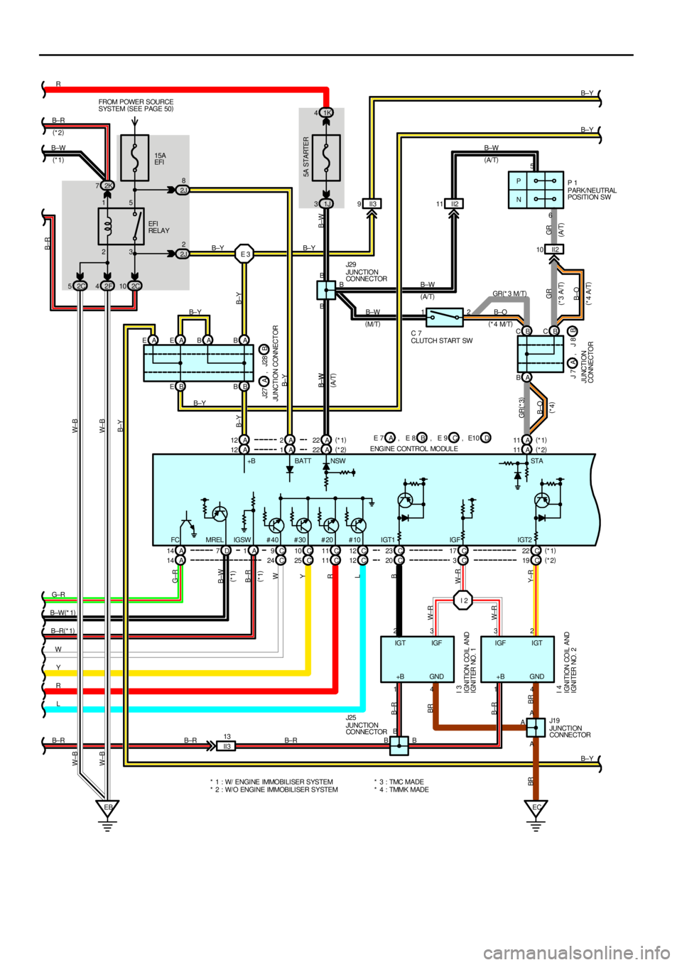
23 15P
N5
6
I 2 15A
EFI FROM POWER SOURCE
SYSTEM (
SEE PAGE 50)
EBEC
5A STARTER
1K 4
2K 7
2F 42C10
B EBB
A 14 D7A1C9C10 C17 C 23 C22 A 12A B
A 1A22 A11 1J 3
4 1 4 1
A2 3 3 2 B
B±Y Y W B±R(
*1) B±W(
*1) G±RB± RR
B±Y
B±W
B±O B±W
B± Y
B±Y
Y± R W±R W±RBB± Y B±Y
B±WB± Y
B±YB±R
W±B W±B
B±W
B±W
GR
B±O B±O GR(
*3)
GR BR B±RBRG±R
B±W
B± R
W
Y
W±R
B
FC #40 #30 #20 #10 IGT1 IGF IGT2+B BATT NSW STA(
*4 M/T)
(
*4 A/T) (
*4)
(
A/ T)
(
A/ T)
(
M/T)PARK/NEUTRA
LPOSITION SW
JUNCTION
CO NNE CTOR EFI
RE LA Y
J29P 1
* 1 : W/ ENGINE IMMOBILISER SYSTEM
* 2 : W/O ENGINE IMMOBILISER SYSTEM* 3 : TMC MADE
* 4 : TMMK MADEJUNCTION
CONNECTOR
IGNITION COIL AND
IGNITER NO. 1
IGNITION COIL AND
IGNITER NO. 2
J19
I 3
I 4
A A
BRB±R
2 1
CLUTCH START SW C 7II2 10 II2 11
E 3B±Y
BB
B JUNCTION
CO NNE CTOR J25
B± RIGTIGF IGFIGT
+B GND GND+B
II3 13
B±R B± RC 12 C 11 MREL IGSW
R
LA 14 C24 C25 C11 C12 C3 C 20 C19(
*1)
(
*2)
R (
*1)
L (
*1)
B±Y
II3 9
(
A/ T) (
*3 A/T)
A EAEABB B±W(
*2)
(
*1)
2J8
2J2
A 11 B± Y
A 12 A2A22(
*1)
(
*2)(
*1)
(
*2)
J27
JUNCTION CONNECTORB A, J28
E 7
ENGINE CONTROL MODULEB A, E 8 C, E 9 D, E10 2C 5W±B W±B
A BB CBC GR(
*3 M/T)J 7
JUNCTION
CONNECTORB A, J 8 B±W B±W
B±W
(
A/T)
Page 4313 of 4592

ENGINE CONTROL (5S±FE)
This system utilizes an engine control module and maintains overall control of the engine, transmission and so on. An outline
of the engine control is explained here.
1. INPUT SIGNALS
(1) Engine coolant temp. signal circuit
The engine coolant temp. sensor detects the engine coolant temp. and has a built±in thermistor with a resistance which
varies according to the engine coolant temp. thus the engine coolant temp. is input in the form of a control signal into
TERMINAL THW of the engine control module.
(2) Intake air temp. signal circuit
The intake air temp. sensor detects the intake air temp., which is input as a control signal into TERMINAL THA of the
engine control module.
(3) Oxygen sensor signal circuit
The oxygen density in the exhaust gases is detected and input as a control signal into TERMINAL OX1 (except
California) and OX2 of the engine control module.
(4) RPM signal circuit
Camshaft position and crankshaft position are detected by the camshaft position sensor and crankshaft position sensor.
Camshaft position is input as a control signal to TERMINAL G+ of the engine control module, and engine RPM is input
into TERMINAL NE+.
(5) Throttle signal circuit
The throttle position sensor detects the throttle valve opening angle, which is input as a control signal into TERMINAL
VTA of the engine control module.
(6) Vehicle speed signal circuit
The vehicle speed sensor, installed inside the transmission, detects the vehicle speed and inputs a control signal into
TERMINAL SPD of the engine control module.
(7) Park/Neutral position SW signal circuit (A/T)
The Park/Neutral position SW detects whether the shift position are in neutral, parking or not, and inputs a control signal
into TERMINAL STA of the engine control module.
(8) A/C SW signal circuit
The A/C amplifier function is built in the engine control module. The A/C SW signal inputs into the TERMINAL A/C SW of
the engine control module.
(9) Battery signal circuit
Voltage is constantly applied to TERMINAL BATT of the engine control module. When the ignition SW is turned on, the
voltage for engine control module start±up power supply is applied to TERMINAL +B of engine control module via EFI
relay.
(10) Intake air volume signal circuit
Intake air volume is detected by the manifold absolute pressure sensor (for manifold pressure) and is input as a control
signal into TERMINAL PIN of the engine control module.
(11) Starter signal circuit
To confirm whether the engine is cranking, the voltage applied to the starter motor during cranking is detected and the
signal is input into TERMINAL NSW of the engine control module as a control signal.
(12) Engine knock signal circuit
Engine knocking is detected by knock sensor 1 and the signal is input into TERMINAL KNK as a control signal.
(13) Electrical load signal circuit
The signal when systems such as the rear window defogger, headlights, etc. Which cause a high electrical burden are
on is input to TERMINAL ELS as a control signal.
(14) Air fuel ratio signal circuit (California)
The air fuel ratio is detected and input as a control signal into TERMINAL AF+ of the engine control module.
SYSTEM OUTLINE
Page 4319 of 4592
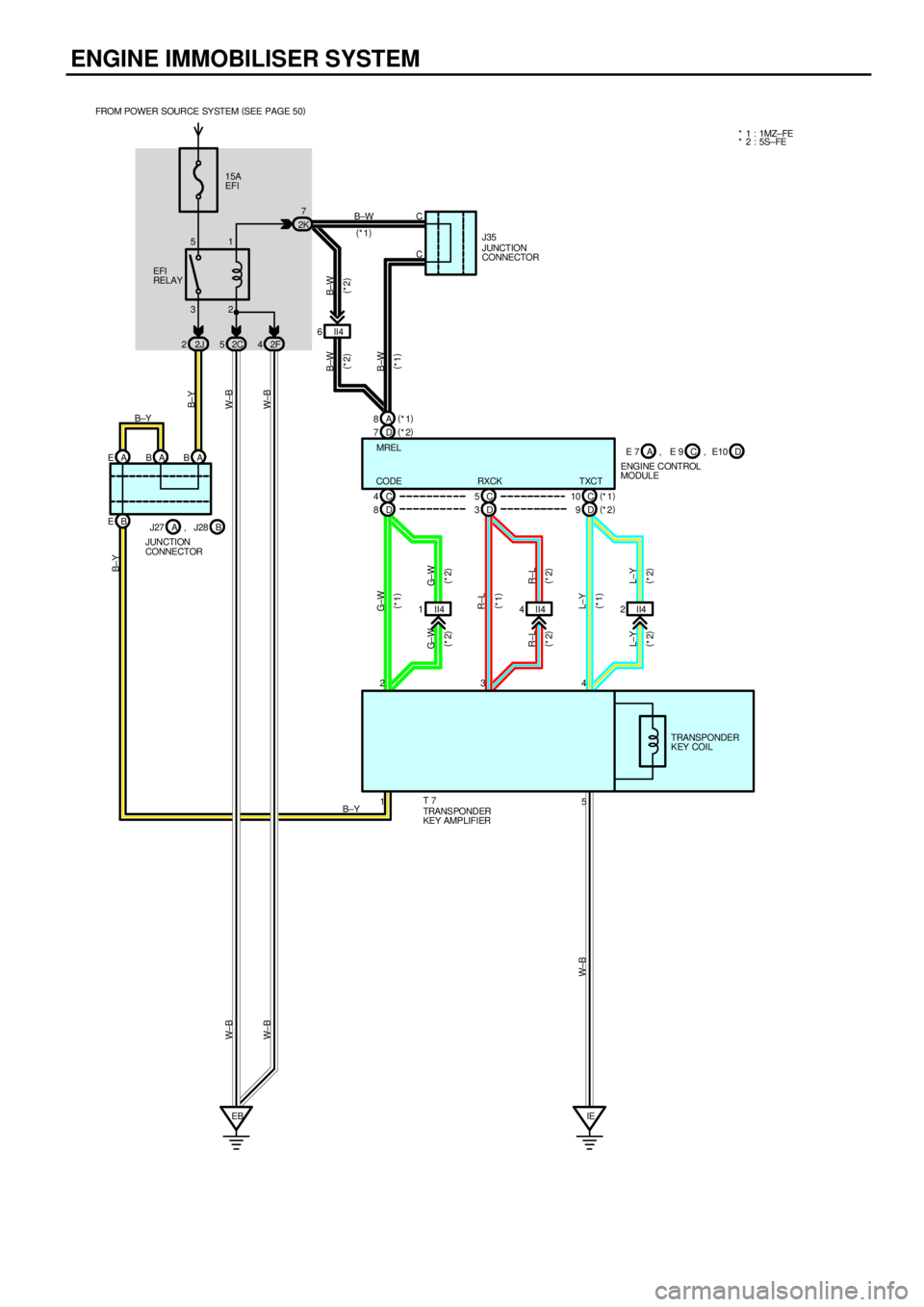
ENGINE IMMOBILISER SYSTEM
15A
EFI
32 51
2J 22C52F42K7
II4 6
D 7(
*2) A 8(
*1)
D 8C 4
D 3C 5
D 9(
*2) C 10(
*1)
II4 1 II44II42 B EA EAB A B
EBIE B±W
(
*1)
B±W
(
*2) B±W
(
*2)
B±W
(
*1) W±B
W±BB±Y
G± W
(
*2)
R±L
(
*2)
L±Y
(
*2) L±Y
(
*2) R±L
(
*2) G± W
(
*2)G±W
(
*1)
W±B
CODE RXCK TXCTMREL FROM POWER SOURCE SY STEM (
SEE PAGE 50)
EFI
RELAY
B±Y
L±Y
(
*1) R±L
(
*1)
E 7
ENGINE CONTROL
MODULEC A, E 9 D, E10
B±Y
J27
JUNCTION
CONNECTORB A, J28
5 1 234
B±YTRANSPONDER
KEY COIL
TRANS PONDER
KEY AMPLIFIER T 7
W± B W± B
* 1 : 1MZ± FE
* 2 : 5S±FE
JUNCTION
CONNECTOR J35 C
C
Page 4427 of 4592
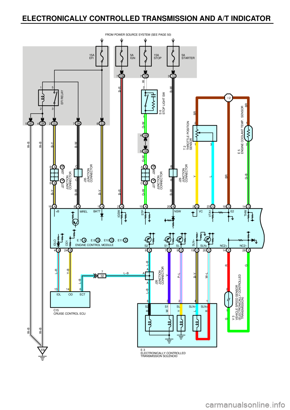
ELECTRONICALLY CONTROLLED TRANSMISSION AND A/T INDICATOR
15A
EFIFROM POWER SOURCE S YS TEM (
SEE PAGE 50)
2J 815A
STOP
1C 7
23 15
2F 42J2
1R 4
1R 51 2
1 2
2 1
A 15 A 1D 2D23 D14 D 18
E 7E9E19 E20 E14 E26 A B
B BI 2
1 2
EBA
63241 A3
G±WB±YB±Y W± B W±B
G± W G±W W
BR
BR G± BL Y
BR L±B L±B
V
P±L
B±Y
W±L
R
G GJUNCTION
CONNECTORB J27 J28AEFI RELAY
SLN+ NC2+ NC2± BA TTVC
STOP LIGHT SW
THROTTLE POSI TI ON
SENSOR
ENGINE COOLANT TEMP. SENSOR
ELECTRONICALLY CONTROLLED
TRANSMISSION SOLENOID
VEHICLE SPEED SENSOR
(
ELECTRONICALLY CONTROLLED
TRANSMISSION)
E 3
V 3S 6
T 2
E 5 B
W
Y
L
R
S2 S1 SL SLN± SLN+ BB24
CRUISE CONTROL ECU C156 13 14
L±BL±R
Y±B
ECT IDL ODA ENGINE CONTROL MODULEB E 7 E 8ADE10 EE11 A 16
B±Y
+B 2C 5
W± B W±B
STP
VTA1
THW IDLO
OD1
SLN± JUNCTION
CONNECTOR J26
L±B5A
IGN
1W 7
A 2
B±RB±R
2K 7
A 8
B±W B±W
C CJUNCTION
CONNECTOR J35
IGSW
S1 SLE2
S25A
STARTER
1J 3
B 20
B±WB±W
B BJUNCTION
CONNECTOR J29
II27
,
,
A A
B C
JUNCTION
CONNECTORB J27 J28A
, , , MRELNSW
4E8
Page 4435 of 4592
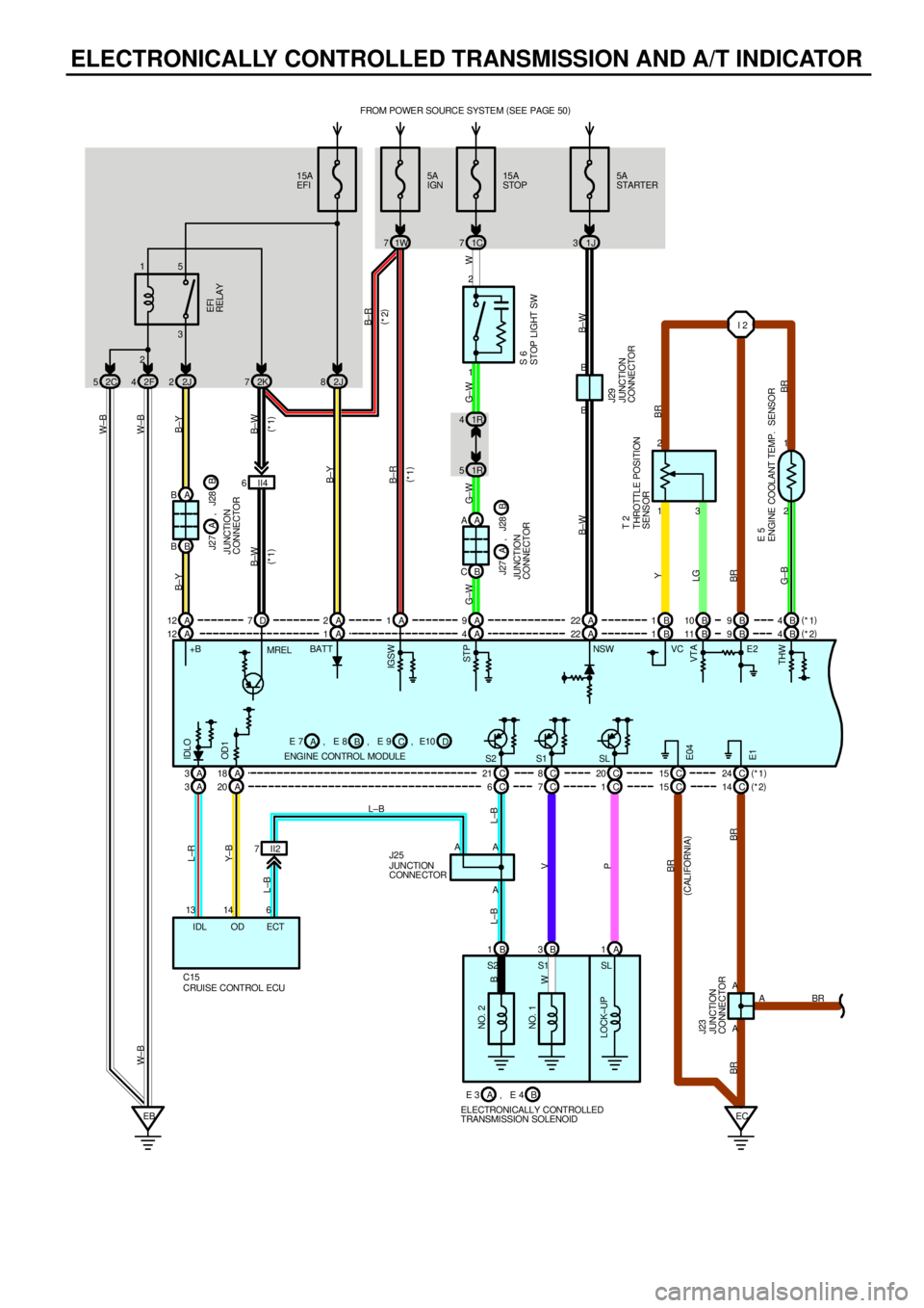
ELECTRONICALLY CONTROLLED TRANSMISSION AND A/T INDICATOR
15A
EFIFROM POWER SOURCE SYSTEM (
SEE PAGE 50)
2J 815A
STOP
1C 7
23 15
2F 42J2
1R 4
1R 51 2
1 2
2 1
A 4 A 1B 1B11 B4 B 9
C 21 C8C20 C24 A B
B BI 2
EBEC A
A A3
AA
G±WB±YB±Y W±B W± B
G± W G± W W
BR
BR G±BLGY
BR L±B L±B
V
P
BR BREFI
RELAY
BATTVC
STOP LIGHT SW
THROTTLE POSITION
SENSOR
ENGINE COOLANT TEMP. SENSORS 6
T 2
E 5 B
W
S2 S1 II2 7 A 3A18
CRUISE CONTROL ECU C156 13 14
L±BL±R
Y± B
ECT IDL ODA ENGINE CONTROL MODULEB ACD A 12
B±Y
+B
JUNCTION
CONNECTOR J23STP
VTA
THW IDLO
OD 1
E1
JUNCTION
CONNE CTOR J25 L±B5A
IGN
1W 7
B±R
2K 7
B±W B±W
IGSW
S1 SLE2
S2B 4 B 9 B 10 B 1 A 9 A 1 A 2 D 7 A 12(
*1)
(
*2) A A
B C
SL
NO. 2
NO. 1
LOCK±UP
B 1B3A1
E 3
ELECTRONICALLY CONTROLLED
TRANSMISSION SOLENOIDB A, E 4C 1 C 7 C 6 A 20 A 3E 7 , E 8 , E 9 , E10
B± R
(
*2)
(
*1)
J27
JUNCTION
CONNECTORB A, J28J27
J UNCTION
CONNECTORB A, J28
II4 6
(
*1) (
*1)
A 22A 225A
STARTER
1J 3
B±W B±W
JUNCTION
CONNECTOR J29
C 14 C 15
C 15
BR
(
CALIFORNIA)
(
*1)
(
*2)
BR B B
E04
MRELNSW 2C 5
W±B
Page 4454 of 4592
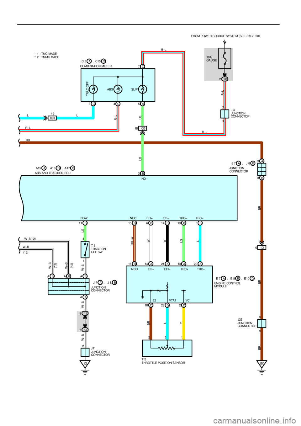
IG 1J 71J 8B 5 B 13 B 14 B 6 B 15
B 16 A14 A21 A13 A20
D 18 D23 D2 B 11
1 4
AA AB A B A B ATRC± TRC+ EFI± EFI+ NE O CSW
BR±W
W
B
LG
L YL BRLG W±B W±B W±BW±B
W±BW± BW± B(
*2)
JUNCTION
CONNECTOR J11
THROTTLE POSITION SENSOR T 2 TRACTI ON
OFF SW T 5 ABS AND TRACTION ECU
JUNCTION
CONNECTOR
E2 VTA1 VC NEO EFI+ EFI± TRC+ TRC±
23110A
GAU GE FROM POWER SOURCE SYSTEM (
SEE PAGE 50)
1D 2
B 3IG3 18A 5 C 4 C 3
IG319C 7
L
R±LLR±L
R±L
LG R±L
LG
R±L
JUNCTION
CONNECTOR J 4 COMBINATION METER
INDD D
TRA C OFF
ABS SLIP
ECII3 6A C
B B
A A BR
BR BR BR
B A15 A , A16 CA17 , C C 8 A , C10
B J 7 A , J 8J 7
JUNCTION
CONNECTORB A, J 8
JUNCTION
CONNECTOR J22 ENGINE CONTROL
MODULEA E 7 BE 8 , D, E10 (
*2)
(
*2)
(
*2)
* 1 : TMC MADE
* 2 : TMMK MADE