Page 4161 of 4592
I GROUND POINT
FRONT TURN SIGNAL
LIGHT AND PARKING
LIGHT LH
FRONT TURN SIGNAL
LIGHT AND PARKING
LIGHT RH
RADIATOR FAN
MOTOR
WASHER LEVEL
WARNING SW
WATER TEMP. SW
NO. 1
FAN NO. 2 RELAYABS SOL RELAY
FAN NO. 3 RELAY
HTR RELAY
ENGINE MAIN RELAY
EFI RELAY
FRONT WIPER MOTORABS ACTUATOR
1
1
1EA12
E 2 E 2
E 2
E 2
E 2
E 2
E 2
2J 10
2F4
2C 5
EB3
E 1
EA W±B W±B W±B W±B W±B
W± B
W±B
W±B
W±BW±B
W±B W± B W±B W±B W± B W±B W± B
W±B
W±B
W± B
W±B
W±B
W±B
Page 4170 of 4592

J
FuseSystemPage
15APOWER±OUTLETPower Outlet130
15ASTOP
ABS
Cruise Control
Electronically Controlled Transmission and A/T Indicator
Engine Control
Shift Lock
Stop Light11 2
108
102
54
122
74
25ADOOR
Door Lock Control
Interior Light
Key Reminder and Seat Belt Warning
Light Auto Turn Off
Power Window98
76
128
68
94
25AWIPERWiper and Washer90
30APOWERDoor Lock Control
Power Window98
94
40AAM1Charging
Radiator Fan and Condenser Fan52
144
40ADEFRear Window Defogger and Mirror Heater134
Engine Room J/B No.2 (See Page 24)
FuseSystemPage
5AALT±SCharging52
7.5ADOME
Cigarette Lighter and Clock
Combination Meter
Interior Light
Key Reminder and Seat Belt Warning
Light Auto Turn Off126
138
76
128
68
10AECU±BCombination Meter
SRS66
68
10AHAZARDTurn Signal and Hazard Warning Light48
10AHORNHorn52
15AHEAD (LH)Headlight144
15AHEAD (RH)Headlight144
20AEFIElectronically Controlled Transmission and A/T Indicator
Engine Control102
54
20ARADIO NO.1Radio and Player48
30AAM2
Charging
Electronically Controlled Transmission and A/T Indicator
Engine Control
Starting and Ignition136
102
54
66
30ACDSRadiator Fan and Condenser Fan66
30ARDIRadiator Fan and Condenser Fan138
*These are the page numbers of the first page on which the related system is shown.
Page 4190 of 4592

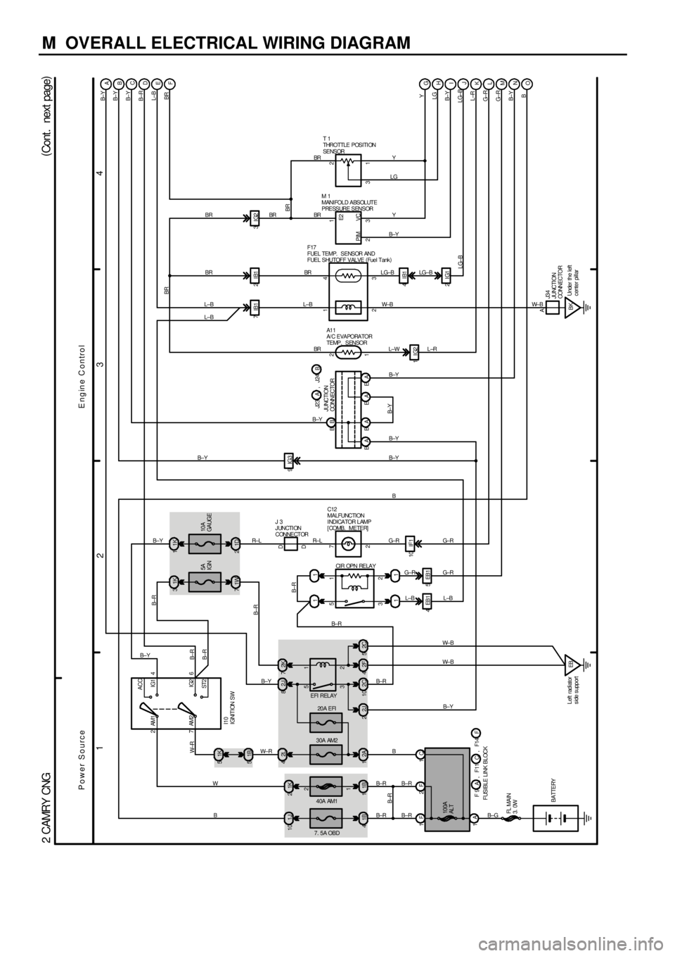
M OVERALL ELECTRICAL WIRING DIAGRAM
1
234
(
Cont . next page)
2 CAMRY CNG
EFI RELAYCIR OPN RELAY
20A EFI
40A AM1 30A AM2
7. 5A OBD
2 1
3 5
2 1
3 5 1J 10 1K22L 41K 5
82J 2K7
11
1B 41B12A12C10 2J 22F4
11 1B 5
L±B
AM2 6
I10
IGNITION SW4 AM1
ST2IG2
2 IG1 ACC
7 2
11K 31K
5A
IGN
4EB1 5EB1
EB Left radiator
s ide s upport 1F 2F 1C
1A
B±G
BATTERY10A
GA UGE
71WB± Y B± Y
1D 2B± Y
FUSIBLE LINK BLOCK10 IF1
FL MAIN
3. 0WBA
100A
AL T
B±Y
1B±R
BB W±R
2
B±R
BR
IG3 9
BR
A
B±R
B±RB
Y
C
LG
Y
B±Y
LG±B
L±W
B±Y
B±Y B±Y
R± L G± R G± R
2
G± R
3
BB±Y W± B M 1
MANIFOLD ABSOLUTE
PRESSURE SENSORT 1
THROTTLE POSITI ON
SENSOR
B±RL±B L±B
L±B G±R
W± R
W
B
IG2 1
B± R F17
FUEL TEMP. SENSOR AND
FUEL SHUTOFF VALVE (
Fuel Tank)
B± R
1
A1 1
A/ C EVAPORATOR
TEMP. SENSOR
ON ML KJI H G
B±R
Y
LG
B± Y
LG±B
L±R
G±R
G±R
B± Y
B
C12
MALFUNCTION
I NDI CA TOR L AMP
[COMB. METER]
7
2 D D
J 3
JUNCTION
CONNECTOR
JUNCTION
CONNECTOR
B±Y
23 31 1
12
R± LB
PIM VCE2
B± R
Power SourceEngine Control
D
E
F
BR
4IB1 BR
3IG2
BR BR
7IB1
LG±B
EA
W±B
L±R
EA BAL±B
B±YB± Y
, F11 F 9 A C , F14 FB J23 J24A,
2C 5
W± B
B±Y L±B
2IG1
BKUnder the left
center pillar B±RB±R
B±Y
B±R
A
J34
JUNCTION
CONNECTOR
W± B
LG±BBR
B± R BR
2IB1
BR4BR
Page 4194 of 4592

1
234
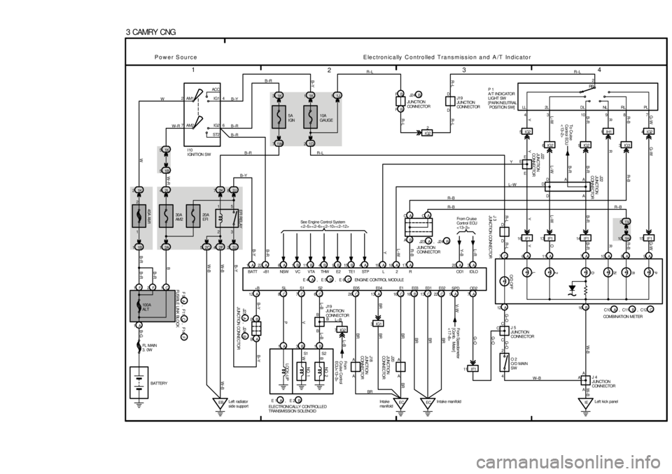
3 CAMRY CNG
2ACC
IG1
IG2
ST2 AM1 4
+B 6 7AM2
1K 5
1B 5
2L 4
30A
AM2
40A AM1
1K 2
1B 12A120A
EFI
2 1
3 5 2K 72J8
2F 42J2
1C 1F 2F
1A1K 3
5A
IGN
71W
12 A
BA BB
EBLeft radiator
s ide s uppor t8C 7C 6CCA CA
AB 10A
GAUGE 11K 1J1
1D 2
16 C 13 C 22 C
IELeft kick panel 12 A 16 B
4 2 7C 6A 11A 7A 10A 8A 9A43 109872
LL 2L DL NL RL PL
4IG2
3IG3 1IH1
9IG2 6IG2 5IG2
15 IF1 14 I F1 13 IF1 16 IF1 1H101V 5 IG22
EC Intake
ma n i f o l dECIntake manifoldY
AC R± L
A D
W± BA D
G±W
1
B
FUSI BL E LI NK BL OCK
L±W D
E
R± B
A R± B
A CR±L
D
J22
JUNCTION
CONNECTORD R±L
D
F 9
A W
E
,
E B±YD
W± R
B
C
A B±R
F11
B±Y
A
B±R
2JUNCTION CONNECTOR
B
R± B
R
BATTERY
B± R
O/ D OFF L±WJ22
JUNCTION
CONNECTOR
YYL±W
FL MAIN
3. 0W
B± R
G±O RR± B G±W
See Engine Cont rol Sys tem
<2±5><2±6><2±10><2±12>
G±W
J20
JUNCTION
CONNECTOR R±B
R
L B±R
O
Y
R±L B±R
L±W
YW± B
G±O
J19
JUNCTION
CONNE CT OR
G± O
BR
BR
BR BR
J19
JUNCTION
CONNE CT OR 100A
AL T
L±B
L±B
JUNCTION
CONNECTOR
L±B
J23
V
B
P
J24
R±BR
B± Y B± Y
2 L
W
E2
B
I10
IGNITION SW
B±Y
THW
W±B B±Y
VTA
Y
VC
B
B± R
NS W
B±R B±R
BATT
B±G WW± R R±L
E02
R±L
B± Y
E0 1 B±R
W± B
E1 E0 4
BR
S2 SL S1ENGI NE CONTROL MODULE
EFI RELAY
W± B
J 5
JUNCTION
CONNECTOR
J 3
JUNCTION CONNECTOR2 D N R P
J 4
JUNCTION
CONNECTOR O 2
O/D MAI N
SW
Electronically Controlled Transmission and A/T Indicator Power Source
S1 S2L±B
Fr om
Cruis e Cont rol
ECU< 13±3>
16 A 13
L±RIDLO
IF1 11G±O
C OD 2
Y± BOD1Fr om Cr uis e
Cont rol ECU
< 13±3>RB
E03
BRB
V± W
7IG2
From Speedometer
[Comb. Meter]
< 17±8>
1A 3B 1B
ELECTRONICALLY CONTROLLED
TRANSMISSI ON SOLENOIDST P TE1
NO. 1 NO. 2
LOCK±UP
9ASPD
B±R
1A A6 1B 11B 4B 9B 19A 18A 17A 3A20 A 15 B 4 A 22 A
7A +B 1B J23 J24A,
, FF14
, E 2 E 1 A BA,
, E 5 E 4 A B , E 6 C 2C 5
W±B To Cruise
Control ECU
< 13±2>
FB FB
J24
JUNCTION
CONNE CTORB
B±R
3IG1
BR
26 C
A A
J18
JUNCTION
CONNECTOR
BR
P 1
A/T I NDICATOR
LIGHT SW
[PARK/NEUTRAL
POSITION SW]
B± RA
R±B
BR
R± L
L±W
C10 C11,
COMBINATI ON METERABC12, C E0 5
R±L
Page 4229 of 4592

A INTRODUCTION
This manual consists of the following 12 sections:
No.
SectionDescription
A
INDEXIndex of the contents of this manual.
A
INTRODUCTIONBrief explanation of each section.
BHOW TO USE THIS
MANUALInstructions on how to use this manual.
CTROUBLE±
SHOOTINGDescribes the basic inspection procedures for electrical circuits.
DABBREVIATIONSDefines the abbreviations used in this manual.
E
GLOSSARY OF
TERMS AND
SYMBOLS
Defines the symbols and functions of major parts.
FRELAY LOCATIONSShows position of the Electronic Control Unit, Relays, Relay Block, etc.
This section is closely related to the system circuit.
GELECTRICAL
WIRING ROUTINGDescribes position of Parts Connectors, Splice points, Ground points, etc.
This section is closely related to the system circuit.
INDEXIndex of the system circuits.
H
SYSTEM CIRCUITS
Electrical circuits of each system are shown from the power supply through ground
points. Wiring connections and their positions are shown and classified by code
according to the connection method. (Refer to the section, ºHow to use this manualº).
The ºSystem Outlineº and ºService Hintsº useful for troubleshooting are also contained
in this section.
IGROUND POINTSShows ground positions of all parts described in this manual.
J
OVERALL
ELECTRICAL
WIRING DIAGRAM
Provides circuit diagrams showing the circuit connections.
KPOWER SOURCE
(Current Flow Chart)Describes power distribution from the power supply to various electrical loads.
LPART NUMBER OF
CONNECTORSIndicates the part number of the connectors used in this manual.
Page 4236 of 4592

B
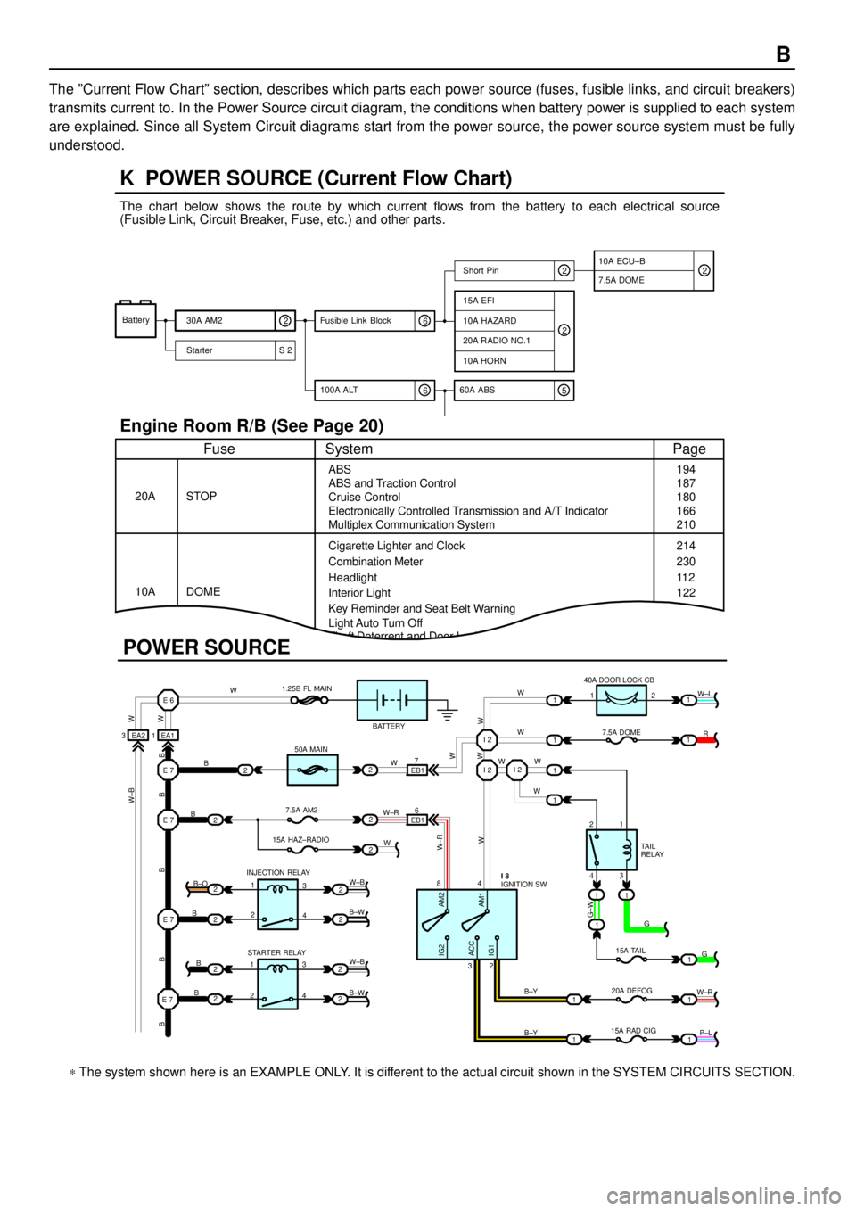
The ºCurrent Flow Chartº section, describes which parts each power source (fuses, fusible links, and circuit breakers)
transmits current to. In the Power Source circuit diagram, the conditions when battery power is supplied to each system
are explained. Since all System Circuit diagrams start from the power source, the power source system must be fully
understood.
Theft Deterrent and Door Lock Control
K POWER SOURCE (Current Flow Chart)
11
1
EA1 1EA2 3
7
EB16
E 6
E 7I 2I 2
I 2
E 7
E 7
E 7
2
1
1
2
2
2
2
2
B
B
W W
B B B B BW±B
B
B
B B±O
B±W
W±B
B±W STARTER RELAY INJECTION RELAY15A HAZ±RADIO7.5A AM250A MAIN 1.25B FL MAIN
BATTERY
WWW
W W W
R W±L
W
W
G±W
G
15A TAIL
20A DEFOG
15A RAD CIGTA I L
RELAY 7.5A DOME 40A DOOR LOCK CB
2 1
1 2
4 8
2 3
3 4
G
W±R
P±L B±Y
B±Y
W±R
AM2 IG2
ACC
IG1AM1W W
W±R
W W
W±B
21
1
1
1
1
2
2
2
2
3
4
3
4 1
2
1
22
1
11
1
IGNITION SW I 8
Battery
30A AM2
2
Starter S 220A RADIO NO.1
10A HORN
15A EFI
7.5A DOMEShort Pin
10A HAZARD
The chart below shows the route by which current flows from the battery to each electrical source
(Fusible Link, Circuit Breaker, Fuse, etc.) and other parts.
Engine Room R/B (See Page 20)
ABS
ABS and Traction Control
Cruise Control
Electronically Controlled Transmission and A/T Indicator
Multiplex Communication System
Cigarette Lighter and Clock
Key Reminder and Seat Belt Warning STOP
Fuse Page
194
214
11 2
System
DOME 20A
10ACombination Meter
Headlight
Interior Light
2
2
6 100A ALT
EB1
POWER SOURCE
Light Auto Turn Off187
180
166
210
230
122
10A ECU±B
5 60A ABS
2
6 Fusible Link Block2
* The system shown here is an EXAMPLE ONLY. It is different to the actual circuit shown in the SYSTEM CIRCUITS SECTION.
Page 4275 of 4592
POWER SOURCE
1260A FL ABS
1260A FL ABS 3
3
1
1
2B2
2A1
2B33
3
3
1240A MAIN
EB B 1F1F2E1
A 1C1D1 E 33
1
1
1
2L4
2G3
2G4 2C5
2K63
3
3
3
3 16
5
1
1
4
4
1
3
4
1
3
1
44
3
2
3
2
5
2
5
2
3 2 B
B
BB±R L±WL±B L±R
L±B W±B B±G
B±G L
GR±LR±LGR GR±R
W± L
W±B
W± R
B±R
W±B
W±R
R
R±L
B±GB±G
B±G
B±G
B±R B±R
B±R
L±B
W±B
W±B
W±B R±B
BATTERY
FL MAIN 3. 0W
100A
ALT50A
HTR GENERATOR G 1
ABS SOL RELAY
AB S MOTOR RELAY
HTR RELAY
ENGINE MAIN RELAY
15A EFI
10A HAZARD
20A RADIO NO. 1
10A HORN
30A AM2
SHORT PIN
5A ALT±S
HEAD RELAY
15A HEAD (
RH)(
*9)
15A HEAD RH(
UPR)(
*8)
15A HEAD (
LH)(
*9)
15A HEAD LH(
UPR)(
*8)
(
5S±FE W/O ABS)
(
*7, *2 *4)
(
*2 *5)
(
*7, *2 *4)
(
*2 *5)
GR±R
30A CDS30A RDI
1 1
2 2
10A ECU±B
7. 5A DOME
(
*8)
(
*8)
(
*9)
112
1
10A A/C
2F4
W±B
B±R
12
3
25
1
ST RELAYL±R 5
13
22
2 2
2B
(
*6)
W±B
(
*6) B±W
(
*6) L
(
*6)
A/F HTR RELAY
1 1
W
(
*6) FL 1. 25B25A A/F HTR
F 4 BA, F 5
F 7
FUSIBLE LINK BLOCKE D, F 8C , F 6
F , F 9L
(
*6)
,
1 2(
*3)(
*3)
Page 4292 of 4592

2K 7
2F 42C10 23 15
E 4E3E2E1DD5 B BBB A BAB
A 16 A1
EB15A
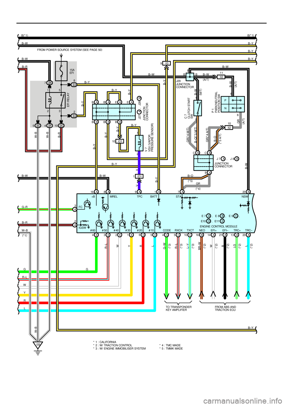
EFI FROM POWER SOURCE SYSTEM (
SEE PAGE 50)
II3 9
B±Y B±Y B±Y
B±Y B±W
B±R
G
R±L
W
Y
R
LB±Y
B±YB±YB±R W± B
R±L
W
Y
R
L W± B
EFI RELAY
B±Y
+B BATT
ENGINE CONTROL MODULEB E 7 E 8ACE 9 FC
#60 #50 #40 #30 #20 #10 2C 5
W± B
B 16NEO
BR±W
A 14EFI+
W
A 21EFI±
B
A 13TRC+
LG
A 20TRC±
L
FROM ABS AND
TRACTI ON ECU 2J8
A EAE
B±Y
, , ,
A2
B±R
W± B B±W B±W
2
2J
B±W
B±Y B±Y
B(
*1)
B(
*1)
B±Y
B± Y
D E10 EE11 , 3
A G±R
G IGSWMRELA BB C
A 7P
N5 B±W B
JUNCTION
CONNECTORB J 7 J 8A
PARK/NEUTRAL
POSITION SW
JUNCTION
CONNECTOR
P 1
J29
STAB 20 B
B± W
, B
II2 11
10
II2 2 1
GR(
*4 A/T)B±W
B±W
B±O
GR
* 1 : CALIFORNIA
* 4 : TMC MADE
* 3 : W/ ENGINE IMMOBILISER SYSTEM6
B± O
GR
B±W(
A/T)(
M/T)
(
*5)
(
*4)
(
*5 A/T)C 7
CLUTCH START
SW
(
A/T)
A 8B±W
* 2 : W/ TRACTION CONTROLC 10TXCT
L±Y
C 5RXCK
R±L
C 4CODE
G±W
TO TRANSPONDER
KEY AMPLIFIER
(
*3)
(
*3)
(
*3)
6
(
*1)
(
*2)
(
*2)
(
*2)
(
*2)
(
*2)(
A/T)
B C
B±O(
*5 M/T) GR(
*4 M/T)
B B
NSW A 9ID1 1
VV
ID1 10
B±Y
2 1VSV (
VAPOR
PRESSURE SENSOR) V 7
B± Y
J27
JUNCTION
CONNECTORB A, J28
TPC
* 5 : TMMK MADE