Page 2268 of 4592
A09403
ECM
+B 12
E4 B±Y J/C
B
J24 J23B
B±Y
Instrument
Panel J/B 22J 2K7
W±R EFI
Relay 1 3
52
2F4
W±B
2A 1
AM2
42L
B
FL
Block
MAIN
FL
B±GEngine
J/B No.2
5
1B
531K71W
IGN
1K
Room
W±R
IG
Switch
7 6
E6
BR
B±R
EC
E1
F11
F9EB
1
1
EFI
J20
J/C A
A
Battery
BR
16 B±R DI±116
± DIAGNOSTICSENGINE
ECM Power Source Circuit
CIRCUIT DESCRIPTION
When the ignition switch is turned ON, battery positive voltage is applied to the coil, closing the contacts of
the EFI main relay (Marking: EFI) and supplying power to terminal +B of the ECM.
WIRING DIAGRAM
DI01L±07
Page 2269 of 4592
A09291BE6653
A09273
ON
+B
E1
(±) (+)
± DIAGNOSTICSENGINE
DI±117
INSPECTION PROCEDURE
1 Check voltage between terminals +B and E1 of ECM connector.
PREPARATION:
(a) Remove the glove compartment (See Pub. No. RM654U,
page SF±64).
(b) Turn the ignition switch ON.
CHECK:
Measure the voltage between terminals +B and E1 of the ECM
connector.
OK:
Voltage: 9 ± 14 V
OK Proceed to next circuit inspection shown on
Problem symptoms table (See page DI±21).
NG
2 Check for open in harness and connector between terminal E1 of ECM and body
ground (See page IN±29).
NG Repair or replace harness or connector.
OK
3 Check EFI main relay (Marking: EFI) (See Pub. No. RM654U, page SF±40).
NG Replace EFI main relay.
OK
4 Check EFI fuse (See page DI±110, step 2).
NG Check for short in all harness and components
connected to EFI fuse.
OK
Page 2270 of 4592
A00355
IGN Fuse
Instrument Panel J/B
DI±118
± DIAGNOSTICSENGINE
5 Check for open in harness and connector between EFI main relay (Marking: EFI)
and battery, and EFI main relay and ECM (See page IN±29).
NG Repair or replace harness or connector.
OK
6 Check IGN fuse.
PREPARATION:
Remove the IGN fuse from the instrument panel J/B.
CHECK:
Check the continuity of the IGN fuse.
OK:
Continuity
NG Check for short in all harness and components
connected to IGN fuse.
OK
7 Check ignition switch (See Pub. No. RM654U, page BE±14).
NG Replace ignition switch.
OK
Check for open in harness and connector between ignition switch and EFI main relay, and EFI
main relay and body ground (See page IN±29).
Page 2384 of 4592
DI1B1±15
H01357
C5
C4C6
287 8 9 10 16 17
18A B12 3 4 5 6
11 12 15 14 13
AABB
19 20 21 22 23 24 25 26 27 1 2 3 4 5 6
7 8 9 10 11 121 2 3 4 5 6
7 8 9 10 11 12 DI±232
± DIAGNOSTICSSUPPLEMENTAL RESTRAINT SYSTEM
TERMINALS OF ECU
No.SymbolTerminal Name
A±Electrical Connector Check Mechanism
B±Electrical Connector Check Mechanism
C5 ± 3LASRS Warning Light
C5 ± 4GSWEFI ECU
C5 ± 5IG2Power Source (IGN Fuse)
C5 ± 6ACCPower Source (CIG Fuse)
C5 ± 9SR+Front Airbag Sensor (RH)
C5 ± 10P+Squib (Passenger)
C5 ± 11P±Squib (Passenger)
C5 ± 12SILDiagnosis
C5 ± 13D±Squib (Driver)
C5 ± 14D+Squib (Driver)
C5 ± 15SL+Front Airbag Sensor (LH)
C5 ± 19TcDiagnosis
C5 ± 20SR±Front Airbag Sensor (RH)
C5 ± 26SL±Front Airbag Sensor (LH)
C5 ± 27E1Ground
C5 ± 28E2Ground
C4 ± 1PL±Squib (Seat Belt Pretensioner, LH)
C4 ± 2PL+Squib (Seat Belt Pretensioner, LH)
C6 ± 5PR+Squib (Seat Belt Pretensioner, RH)
C6 ± 6PR±Squib (Seat Belt Pretensioner, RH)
Page 2519 of 4592
EC03B±03
B06549
VSV for EGR Front TWC
(California)EGR Vacuum Modulator
EGR
Valve
TWC (Except California)
Rear TWC (California)VSV
for EVAP
Vent Line
Charcoal CanisterFuel Tank EVAP Line
Air Drain HoseFiller Pipe
Air Inlet Line Purge LineEVAP Service Port
Fuel Tank Cap
Vapor
Pressure
SensorVSV for Vapor
Pressure Sensor
± EMISSION CONTROL (5S±FE)PARTS LAYOUT AND SCHEMATIC DRAWING
EC±3
1401 Author�: Date�:
DRAWING
Page 2672 of 4592
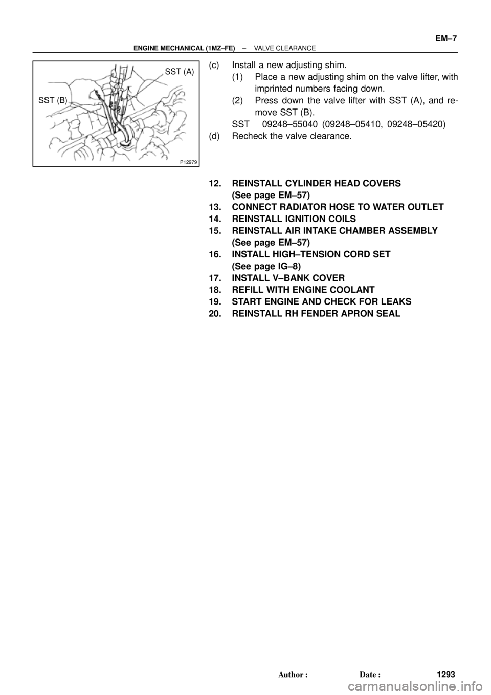
P12979
SST (A)
SST (B)
± ENGINE MECHANICAL (1MZ±FE)VALVE CLEARANCE
EM±7
1293 Author�: Date�:
(c) Install a new adjusting shim.
(1) Place a new adjusting shim on the valve lifter, with
imprinted numbers facing down.
(2) Press down the valve lifter with SST (A), and re-
move SST (B).
SST 09248±55040 (09248±05410, 09248±05420)
(d) Recheck the valve clearance.
12. REINSTALL CYLINDER HEAD COVERS
(See page EM±57)
13. CONNECT RADIATOR HOSE TO WATER OUTLET
14. REINSTALL IGNITION COILS
15. REINSTALL AIR INTAKE CHAMBER ASSEMBLY
(See page EM±57)
16. INSTALL HIGH±TENSION CORD SET
(See page IG±8)
17. INSTALL V±BANK COVER
18. REFILL WITH ENGINE COOLANT
19. START ENGINE AND CHECK FOR LEAKS
20. REINSTALL RH FENDER APRON SEAL
Page 2840 of 4592

± INTRODUCTIONTERMS
IN±37
37 Author�: Date�:
DCDirect Current
DEFDefogger
DFLDeflector
DIFF.Differential
DIFF. LOCKDifferential Lock
D/INJDirect Injection
DLIDistributorless Ignition
DOHCDouble Over Head Cam
DPDash Pot
DSDead Soak
DSPDigital Signal Processor
ECAMEngine Control And Measurement System
ECDElectronic Controlled Diesel
ECDYEddy Current Dynamometer
ECUElectronic Control Unit
EDElectro±Deposited Coating
EDUElectronic Driving Unit
EDICElectric Diesel Injection Control
EFIElectronic Fuel Injection
E/GEngine
EGR±VMEgr±Vacuum Modulator
ELREmergency Locking Retractor
ENGEngine
ESAElectronic Spark Advance
ETCSElectronic Throttle Control System
EVPEvaporator
E±VRVElectric Vacuum Regulating Valve
EXHExhaust
FEFuel Economy
FFFront±Engine Front±Wheel±Drive
F/GFuel Gage
FIPGFormed In Place Gasket
FLFusible Link
F/PFuel Pump
FPUFuel Pressure Up
FrFront
FRFront±Engine Rear±Wheel±Drive
F/WFlywheel
FW/DFlywheel Damper
FWDFront±Wheel±Drive
GASGasoline
GNDGround
HACHigh Altitude Compensator
H/BHatchback
H±FUSEHigh Current Fuse
HIHigh
Page 2845 of 4592

IACIdle Air ControlIdle Speed Control (ISC)
IATIntake Air TemperatureIntake or Inlet Air Temperature")
IN±42
± INTRODUCTIONTERMS
42 Author�: Date�:
HO2SHeated Oxygen SensorHeated Oxygen Sensor (HO2S)
IACIdle Air ControlIdle Speed Control (ISC)
IATIntake Air TemperatureIntake or Inlet Air Temperature
ICMIgnition Control Module±
IFIIndirect Fuel InjectionIndirect Injection (IDL)
IFSInertia Fuel±Shutoff±
ISCIdle Speed Control±
KSKnock SensorKnock Sensor
MAFMass Air FlowAir Flow Meter
MAPManifold Absolute PressureManifold Pressure
Intake Vacuum
MCMixture Control
Electric Bleed Air Control Valve (EBCV)
Mixture Control Valve (MCV)
Electric Air Control Valve (EACV)
MDPManifold Differential Pressure±
MFIMultiport Fuel InjectionElectronic Fuel Injection (EFI)
MILMalfunction Indicator LampCheck Engine Lamp
MSTManifold Surface Temperature±
MVZManifold Vacuum Zone±
NVRAMNon±Volatile Random Access Memory±
O2SOxygen SensorOxygen Sensor, O2 Sensor (O2S)
OBDOn±Board DiagnosticOn±Board Diagnostic System (OBD)
OCOxidation Catalytic ConverterOxidation Catalyst Convert (OC), CCo
OPOpen LoopOpen Loop
PAIRPulsed Secondary Air InjectionAir Suction (AS)
PCMPowertrain Control Module±
PNPPark/Neutral Position±
PROMProgrammable Read Only Memory±
PSPPower Steering Pressure±
PTOXPeriodic Trap OxidizerDiesel Particulate Filter (DPF)
Diesel Particulate Trap (DPT)
RAMRandom Access MemoryRandom Access Memory (RAM)
RMRelay Module±
ROMRead Only MemoryRead Only Memory (ROM)
RPMEngine SpeedEngine Speed
SCSuperchargerSupercharger
SCBSupercharger BypassE±ABV
SFISequential Multiport Fuel InjectionElectronic Fuel Injection (EFI), Sequential Injection
SPLSmoke Puff Limiter±
SRIService Reminder Indicator±
SRTSystem Readiness Test±
STScan Tool±
TBThrottle BodyThrottle Body
TBIThrottle Body Fuel InjectionSingle Point Injection
Central Fuel Injection (Ci)
TCTurbochargerTurbocharger
TCCTorque Converter ClutchTorque Converter

 (+)
± DIAGNOSTICSENGINE
DI±117
INSPECTION PROCEDURE
1 Check voltage between terminals +B and E1 of ECM connector.
PREPARATION:
(a) Remove the glove compartment (See")

and battery, and EFI main relay and ECM (See page IN±")

EGR Vacuum Modulator
EGR
Valve
TWC (Except California)
Rear TWC (California)VSV
for EVAP
Vent Line
Charcoal CanisterFuel Tank EVAP Line
Air Drain Hos")