Page 1592 of 4592
A00306
135
24 6 IACVIACV closed (VSV: ON)
Throttle Valve30°
3,700 rpm
Engine speed
Throttle valve
opening angle
FI7011 FI6570
A07452
From Battery 2J2
W±B
B±Y
J20
Junction
Connector 9
AAECMACIS
12
MRELB±W
VSV for ACIS
R±Y B±Y 17
2K
2A 2F
51 2
3 4Engine Room J/B
EFI
EBJunction
Connector BB+
B±Y178
E11E7
B
B±YE01
B±W
J36 J35CC
EFI Relay
J27 J28
II3Junction Connector DI±380
± DIAGNOSTICSENGINE (1MZ±FE)
615 Author�: Date�:
IACV Control VSV Circuit
CIRCUIT DESCRIPTION
This circuit opens and closes the IACV (Intake Air Control Valve) in response to the engine load in order to
increase the intake efficiency (ACIS: Acoustic Control Induction System).
When the engine speed is 3,700 rpm or less and the throttle valve opening angle is 60° or more, the ECM
turns the VSV ON and closes the IACV. At all other times, the VSV is OFF, so the IACV is open.
WIRING DIAGRAM
DI08E±06
Page 1594 of 4592
A02041
ON
ACIS (+)
DI±382
± DIAGNOSTICSENGINE (1MZ±FE)
617 Author�: Date�:
3 Check for open and short in harness and connector between EFI main relay
(Marking: EFI) and ECM (See page IN±31).
NG Repair or replace harness or connector.
OK
Check and replace ECM (See page IN±31).
OBD II scan tool (excluding TOYOTA hand±held tester)
1 Check VSV for ACIS (See page SF±60).
NG Replace VSV for ACIS.
OK
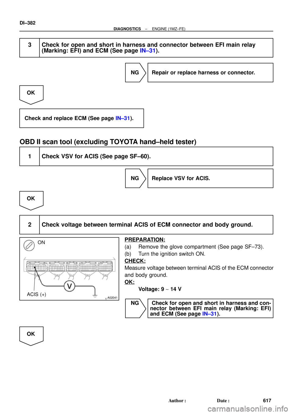
2 Check voltage between terminal ACIS of ECM connector and body ground.
PREPARATION:
(a) Remove the glove compartment (See page SF±73).
(b) Turn the ignition switch ON.
CHECK:
Measure voltage between terminal ACIS of the ECM connector
and body ground.
OK:
Voltage: 9 ~ 14 V
NG Check for open and short in harness and con-
nector between EFI main relay (Marking: EFI)
and ECM (See page IN±31).
OK
Page 1791 of 4592
± DIAGNOSTICSABS & TRACTION CONTROL SYSTEM
DI±579
814 Author�: Date�:
43*
(DI±601)Malfunction in ABS control system�ABS control system
44*
(DI±602)Open or short circuit in NE signal circuit
�NEO circuit
�ECM
�ECU
49
(DI±604)Open circuit in stop light switch circuit
�Stop light switch
�Stop light switch circuit
�ECU
51
(DI±606)Pump motor is locked�ABS pump motor
53*
(DI±608)Malfunction in ECM communication circuit
�TRC+ or TRC ± circuit
�EFI+ or EFI± circuit
�ECM
�ECU
61*
(DI±609)Malfunction in engine control system�Engine control system
Always ON
(DI±610)Malfunction in ECU�ECU
*: TRAC OFF indicator light blinking
Page 1794 of 4592
 ± GND (A15 ±
15, A17 ± 9, 10)R±W e W±BIG switch ONBelow 1.5
SRC1 (A17 ± 5) ± GND (A15 ±
15, A17 ± 9, 10)")
DI±582
± DIAGNOSTICSABS & TRACTION CONTROL SYSTEM
817 Author�: Date�:
MT (A15 ± 14) ± GND (A15 ±
15, A17 ± 9, 10)R±W e W±BIG switch ONBelow 1.5
SRC1 (A17 ± 5) ± GND (A15 ±
15, A17 ± 9, 10)B±R e W±BIG switch ON, TRAC OFF indicator light OFF10 ± 14
SRC2 (A17 ± 6) ± GND (A15 ±
15, A17 ± 9, 10)B±Y e W±BIG switch ON, TRAC OFF indicator light OFF10 ± 14
SMC1 (A17 ± 12) ± GND (A15
± 15, A17 ± 9, 10)Y±R e W±BIG switch ON, TRAC OFF indicator light OFF10 ± 14
SMC2 (A17 ± 6) ± GND (A15 ±
15, A17 ± 9, 10)Y±B e W±BIG switch ON, TRAC OFF indicator light OFF10 ± 14
NEO (A16 ± 15) ± GND (A15 ±
15, A17 ± 9, 10)BR±W e W±BIdlingPulse generation
EFI+ (A16 ± 6) ± GND (A15 ±
15, A17 ± 9, 10)W e W±BIG switch ONPulse generation
EFI± (A16 ± 14) ± GND (A15 ±
15, A17 ± 9, 10)B e W±BIG switch ONPulse generation
TRC+ (A16 ± 13) ± GND (A15 ±
15, A17 ± 9, 10)G e W±BTRAC control activePulse generation
TRC± (A16 ± 5) ± GND (A15 ±
15, A17 ± 9, 10)L e W±BTRAC control activePulse generation
IND (A16 ± 3) ± GND (A15 ±LGWBIG switch ON, SLIP indicator light ONBelow 2.0IND (A16 3) GND (A15
15, A17 ± 9, 10)LG e W±BIG switch ON, SLIP indicator light OFF10 ± 14
WT (A16 ± 12) ± GND (A15 ±LWBIG switch ON, TRAC OFF indicator light ONBelow 2.0WT (A16 12) GND (A15
15, A17 ± 9, 10)L e W±BIG switch ON, TRAC OFF indicator light OFF10 ± 14
CSW (A16 ± 11) ± GND (A15 ±LGWBIG switch ON, TRAC cut switch pushed inBelow 2.0CSW (A16 11 ) GND (A15
15, A17 ± 9, 10)LG e W±BIG switch ON, TRAC cut switch released8 ± 14
Page 1820 of 4592

F00063
ECMABS & TRAC ECU
EFI+
EFI±
TRC+
TRC±EFI+
EFI±
TRC+
TRC±
E7
E7
E7
E7A16
A16
A16
A1614 6
14
13
5W
B
L ECMABS & TRAC ECU
EFI+
EFI±
TRC+
TRC±EFI+
EFI±
TRC+
TRC±E7
E7
E7
E7A16
A16
A16
A16
21
206
14
13
5
W
B
L ECMABS & TRAC ECU
EFI+
EFI±
TRC+
TRC±EFI+
EFI±
TRC+
TRC±E7
E7
E7
E7A16
A16
A16
A166
14
13
5W
B
L
ECMABS & TRAC ECU
EFI+
EFI±
TRC+
TRC±EFI+
EFI±
TRC+
TRC±
E7
E7
E7
E7A16
A16
A16
A166
14
13
5W
B
LG
L
13
DI±608
± DIAGNOSTICSABS & TRACTION CONTROL SYSTEM
843 Author�: Date�:
DTC 53 ECM Communication Circuit Malfunction
CIRCUIT DESCRIPTION
This circuit is used to send TRAC control information from the ABS & TRAC ECU to the ECM (TRC+, TRC±),
and engine control information from the ECM to the ABS & TRAC ECU (EFI+, EFI±).
DTC No.DTC Detecting ConditionTrouble Area
53ECM communication data malfunction is detected.
�TRC+ or TRC± circuit
�EFI+ or EFI± circuit
�ECM
�ECU
WIRING DIAGRAM
INSPECTION PROCEDURE
1 Check for open and short circuit in harness and connector between terminals
EFI+, EFI±, TRC+, TRC± of ABS & TRAC ECU and ECM (See page IN±31).
NG Repair or replace harness or connector.
OK
Check and replace ECM or ABS & TRAC ECU.
DI04S±04
Page 2137 of 4592
I02680
Malfunction Code (Example Code 12, 99)
0.5 Sec. 0.5 Sec.
1.5 Sec. 2.5 Sec.
One Cycle4.5 Sec.
± DIAGNOSTICSENGINE IMMOBILISER SYSTEM
DI±923
1158 Author�: Date�:
(4) When DTC º99º is output, there is a trouble with
immobiliser. Start troubleshooting referring to
PROBLEM SYMPTOM TABLE.
(5) After completing the check, disconnect terminals 13
(TC) and 4 (CG) and turn OFF the display.
HINT:
In the event of 2 or more malfunction codes. indication will begin
from the smaller numbered code and continue in order to the
larger.
(c) Clear the DTC
The following procedures will erase the DTCs and freeze frame
data.
(1) Operating the OBD ll scam tool (complying with
SAEJ1978) or TOYOTA hand±held tester to erase
the codes. (See the OBD ll scan tool's instruction
book for operating instructions.)
(2) Disconnecting the battery terminals or EFI fuse.
Page 2139 of 4592
DI1KI±04
I02682
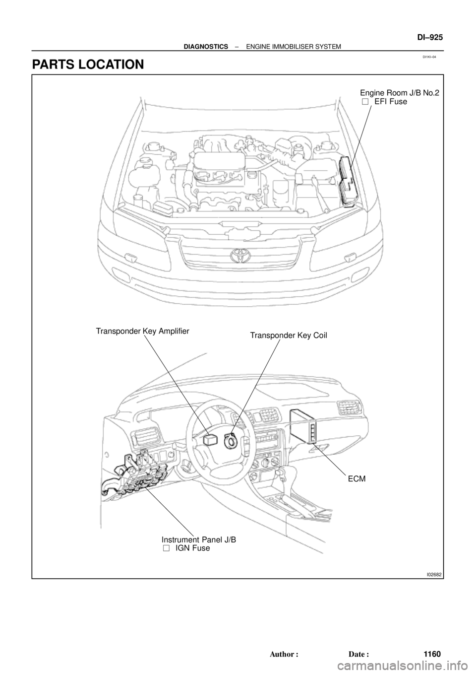
Engine Room J/B No.2
��EFI Fuse
Transponder Key Amplifier
Transponder Key Coil
ECM
��IGN Fuse Instrument Panel J/B
± DIAGNOSTICSENGINE IMMOBILISER SYSTEM
DI±925
1160 Author�: Date�:
PARTS LOCATION
Page 2157 of 4592
 Connect the OBD II scan tool or TOYOTA hand±
held tester to DLC3 under the instrument panel low-
er pad.
(3) Turn the ignition switch ON and turn the OBD II scan
tool")
DI±6
± DIAGNOSTICSENGINE
(2) Connect the OBD II scan tool or TOYOTA hand±
held tester to DLC3 under the instrument panel low-
er pad.
(3) Turn the ignition switch ON and turn the OBD II scan
tool or TOYOTA hand±held tester switch ON.
(4) Use the OBD II scan tool or TOYOTA hand±held
tester to check the DTCs and freezed frame data
and note them down. (For operating instructions,
see the OBD II scan tool's instruction book.)
(5) See page DI±3 to confirm the details of the DTCs.
NOTICE:
�When simulating symptoms with an OBD II scan tool
(excluding TOYOTA hand±held tester) to check the
DTCs, use normal mode. For code on the DTC chart
subject to º2 trip detection logicº, perform the follow-
ing either action.
�Turn the ignition switch OFF after the symptom is
simulated the first time. Then repeat the simulation
process again. When the problem has been simulated
twice, the MIL lights up and the DTCs are recorded in
the ECM.
�Check the 1st trip DTC using Mode 7 (Continuous Test
Results) for SAE J1979.
(c) Clear the DTC.
The DTCs and freezed frame data will be erased by either
action.
(1) Operating the OBD II scan tool (complying with SAE
J1978) or TOYOTA hand±held tester to erase the
codes. (See the OBD II scan tool's instruction book
for operating instructions.)
(2) Disconnecting the battery terminals or EFI fuse.
NOTICE:
If the TOYOTA hand±held tester switches the ECM from
normal mode to check mode or vice±versa, or if the ignition
switch is turned from ON to ACC or OFF during check
mode, the DTCs and freezed frame data will be erased.
3. INSPECT DIAGNOSIS (Check Mode)
HINT:
TOYOTA hand±held tester only:
Compared to the normal mode, the check mode has an in-
creased sensitivity to detect malfunctions.
Furthermore, the same diagnostic items which are detected in
the normal mode can also be detected in the check mode.
(a) Check the DTC.
(1) Initial conditions
�Battery positive voltage 11 V or more
�Throttle valve fully closed
�Transmission in P or N position
�Air conditioning switched OFF
(2) Turn ignition switch OFF.

Throttle Valve30°
3,700 rpm
Engine speed
Throttle valve
opening angle
FI7011 FI6570
A07452
From Battery 2J2
W±B
B±Y
J20
Junction
Connector 9
AAECMACIS
12")