Page 1392 of 4592
BE6653
A03028
A03709
ON
+B (+)
E1
(±)
E1
(±)
+B (+)w/ Immobiliser w/o Immobiliser
DI±180
± DIAGNOSTICSENGINE (5S±FE)
415 Author�: Date�:
INSPECTION PROCEDURE
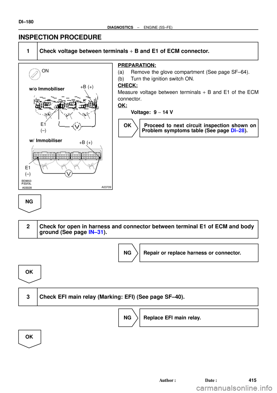
1 Check voltage between terminals + B and E1 of ECM connector.
PREPARATION:
(a) Remove the glove compartment (See page SF±64).
(b) Turn the ignition switch ON.
CHECK:
Measure voltage between terminals + B and E1 of the ECM
connector.
OK:
Voltage: 9 ~ 14 V
OK Proceed to next circuit inspection shown on
Problem symptoms table (See page DI±28).
NG
2 Check for open in harness and connector between terminal E1 of ECM and body
ground (See page IN±31).
NG Repair or replace harness or connector.
OK
3 Check EFI main relay (Marking: EFI) (See page SF±40).
NG Replace EFI main relay.
OK
Page 1393 of 4592
A00355
IGN Fuse
Instrument Panel J/B
± DIAGNOSTICSENGINE (5S±FE)
DI±181
416 Author�: Date�:
4 Check EFI fuse (See page DI±173, step 2).
NG Check for short in all harness and components
connected to EFI fuse.
OK
5 Check for open in harness and connector between EFI main relay (Marking: EFI)
and battery, and EFI main relay and ECM (See page IN±31).
NG Repair or replace harness or connector.
OK
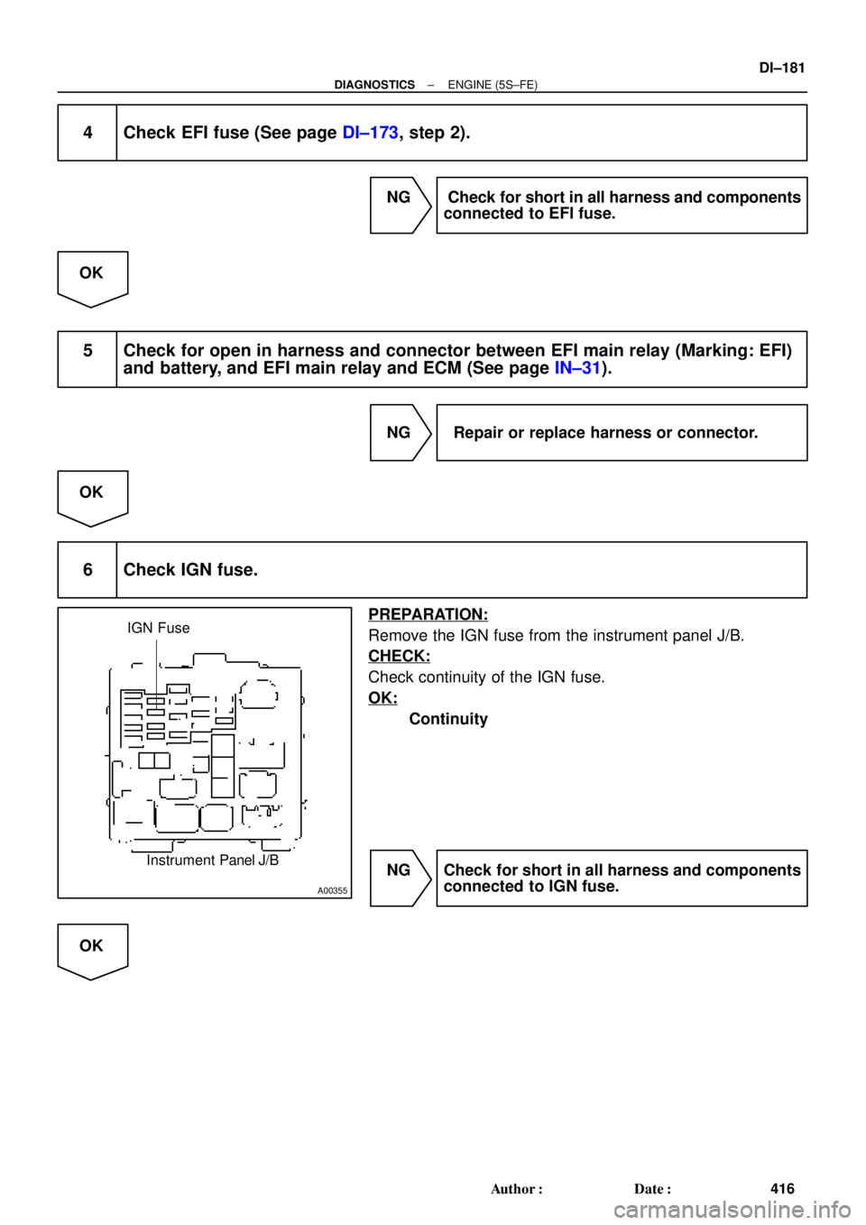
6 Check IGN fuse.
PREPARATION:
Remove the IGN fuse from the instrument panel J/B.
CHECK:
Check continuity of the IGN fuse.
OK:
Continuity
NG Check for short in all harness and components
connected to IGN fuse.
OK
Page 1394 of 4592
DI±182
± DIAGNOSTICSENGINE (5S±FE)
417 Author�: Date�:
7 Check ignition switch (See page BE±14).
NG Replace ignition switch.
OK
Check for open in harness and connector between IG switch and EFI main relay, and EFI main
relay and body ground (See page IN±31).
Page 1395 of 4592
A00325
BatteryMAIN IG Switch
AM2EFI
MAIN
FLStarter ST RelayPark/Neutral Position Switch
(Clutch Start Switch)EFI RelayCIR OPN Relay
Fuel Pump
ECM
FC
Tr
STA
NE (STA Signal)
(NE Signal) IGN
STARTER ST
± DIAGNOSTICSENGINE (5S±FE)
DI±183
418 Author�: Date�:
Fuel Pump Control Circuit
CIRCUIT DESCRIPTION
In the diagram below, when the engine is cranked, current flows from terminal ST of the ignition switch to
the starter relay coil and also current flows to terminal STA of ECM (STA signal).
When the STA signal and NE signal are input to the ECM, Tr is turned ON, current flows to coil of the circuit
opening relay, the relay switches on, power is supplied to the fuel pump and the fuel pump operates.
While the NE signal is generated (engine running), the ECM keeps Tr ON (circuit opening relay ON) and the
fuel pump also keeps operating.
DI01M±05
Page 1396 of 4592
A07555
Battery
EFI
AM2
123
3 1J
B2A
2J Instrument Panel J/B
B
1B 1W
37
1 5
IG Switch
1
B±W
B±RST RelayEFI Relay
5
6
2 3
1 11 410
4
5 4
5
A 2B STARTER
(M/T)
B±G
II23
B±W
II211
Starter
Park/Neutral
Position Switch
Clutch Start
Switch
5 7
B±R Engine Room J/B No.2
2C
2F IGN
FL Block1
2D1
BMAIN
B±O (*3) W±B
GR (*2)
10B
C
1
CIR
OPN
Relay
L±B
IGG±R
W±B
14 2L
E7FCECM
E01
1
S1S2
Engine Room R/B
No.1
2
J40
J/C
G±RL±B
5 93
Fuel
Pump
L±B
R
EB B±R
GR
W±R
B±W
B±WB±O (*3)(A/T)
BL
J/CB±R
J8
2K
J7
B
1 1 1
B 1K
1K
1K
8 7
6
EB1 4
J29
J/C J11
J/CF6 1 W±R
MAIN
FL4
5 2K
2
B±R (*4)
*1: w/ Immobiliser(*1)
MREL
E107 B±W
B
B
B±WII4
6
F41
GR (*2)
*2: TMC Made
*3: TMMK Made A
(*1)
(*1)
GR (*2)
B±O (*3)(M/T)
*4: w/o Immobiliser
EB1 B±R
B±R (*1)
B±R (*4)
IK17
55
7
ID1
7 W±B
W±B
DI±184
± DIAGNOSTICSENGINE (5S±FE)
419 Author�: Date�:
WIRING DIAGRAM
Page 1398 of 4592
A03029A03450
FC (+) ON
w/o Immobiliser
w/ Immobiliser
FC (+)
DI±186
± DIAGNOSTICSENGINE (5S±FE)
421 Author�: Date�:
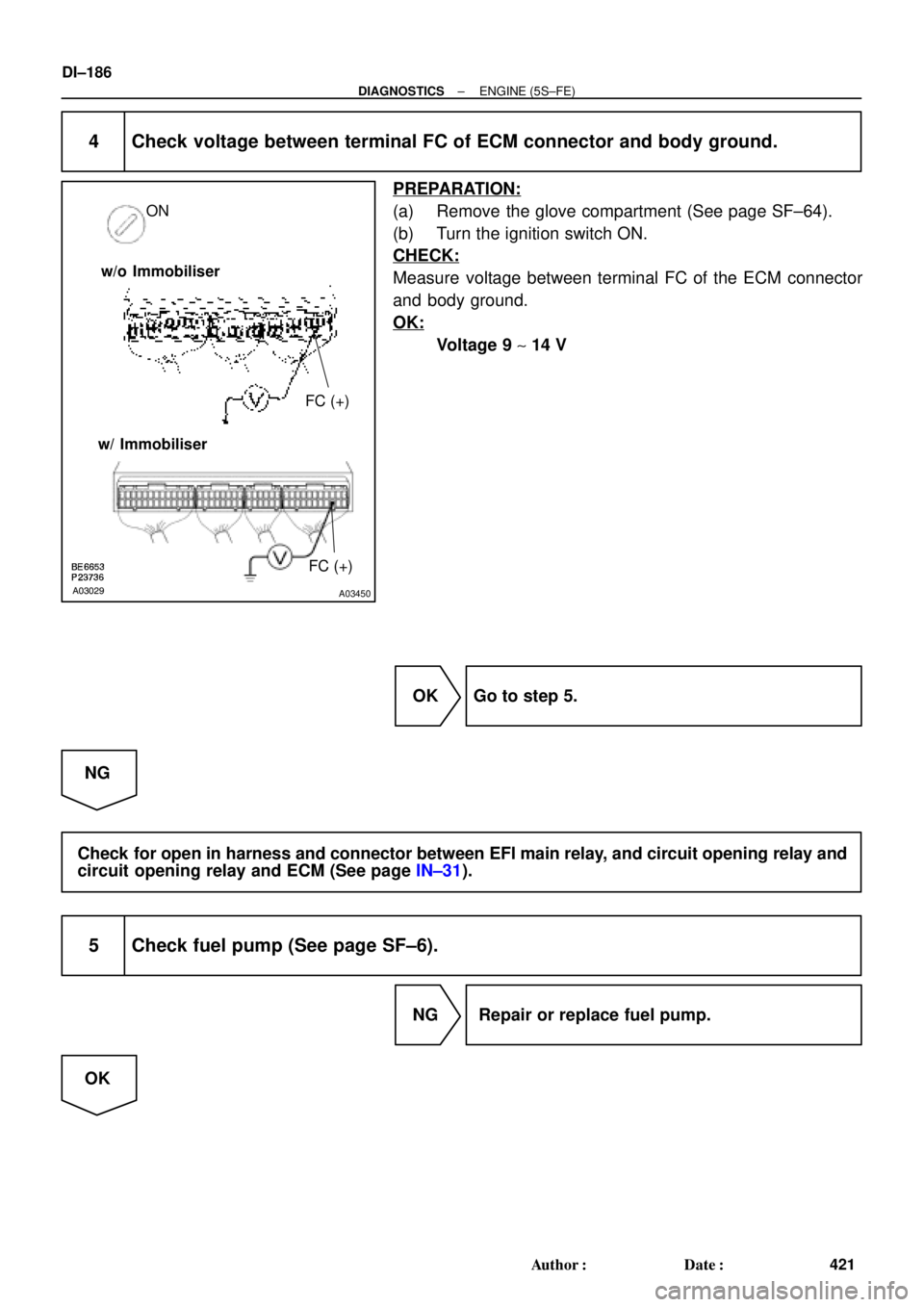
4 Check voltage between terminal FC of ECM connector and body ground.
PREPARATION:
(a) Remove the glove compartment (See page SF±64).
(b) Turn the ignition switch ON.
CHECK:
Measure voltage between terminal FC of the ECM connector
and body ground.
OK:
Voltage 9 ~ 14 V
OK Go to step 5.
NG
Check for open in harness and connector between EFI main relay, and circuit opening relay and
circuit opening relay and ECM (See page IN±31).
5 Check fuel pump (See page SF±6).
NG Repair or replace fuel pump.
OK
Page 1400 of 4592
DI±188
± DIAGNOSTICSENGINE (5S±FE)
423 Author�: Date�:
2 Check for ECM power source circuit (See page DI±179).
NG Repair or replace.
OK
3 Check circuit opening relay (Marking: CIR OPN) (See page SF±41).
NG Replace circuit opening relay.
OK
4 Check voltage between terminal FC of ECM connector and body ground
(See page DI±183, step 4).
OK Go to step 5.
NG
Check for open in harness and connector between EFI main relay and circuit opening relay, and
circuit opening relay and ECM (See page IN±31).
5 Check fuel pump (See page SF±6).
NG Repair or replace fuel pump.
OK
Page 1412 of 4592

435 Author�: Date�:
(2) Connect the OBD II scan tool or TOYOTA hand±
held tester to DLC3 at the lower center of the instru-
ment panel.
(3) Turn the ignition s")
DI±200
± DIAGNOSTICSENGINE (1MZ±FE)
435 Author�: Date�:
(2) Connect the OBD II scan tool or TOYOTA hand±
held tester to DLC3 at the lower center of the instru-
ment panel.
(3) Turn the ignition switch ON and push the OBD II
scan tool or TOYOTA hand±held tester switch ON.
(4) Use the OBD II scan tool or TOYOTA hand±held
tester to check the DTC and freezed frame data and
note them down (For operating instructions, see the
OBD II scan tool's instruction book.).
(5) See page DI±197 to confirm the details of the DTC.
NOTICE:
�When simulating symptoms with an OBD II scan tool
(excluding TOYOTA hand±held tester) to check the
DTC, use normal mode. For code on the DTC chart
subject to º2 trip detection logicº, performe the fol-
lowing either action.
�Turn the ignition switch OFF after the symptom is
simulated the first time. Then repeat the simulation
process again. When the problem has been simulated
twice, the MIL lights up and the DTCs are recorded in
the ECM.
�Check the 1st trip DTC using Mode 7 (Continuous Test
Results) for SAE J1979.
(c) Clear the DTC.
The DTCs and freezed frame data will be erased by either
action.
�Operating the OBD II scan tool (complying
with SAE J1978) or TOYOTA hand±held tes-
ter to erase the codes. (See the OBD II scan
tool's instruction book for operating instruc-
tions.)
�Disconnecting the battery terminals or EFI
fuse.
NOTICE:
If the TOYOTA hand±held tester switches the ECM from
normal mode to check mode or vice±versa, or if the ignition
switch is turned from ON to ACC or OFF during check
mode, the DTCs and freezed frame data will be erased.
3. INSPECT DIAGNOSIS (Check Mode)
HINT:
TOYOTA hand±held tester only:
Compared to the normal mode, the check mode has an in-
creased sensitivity to detect malfunctions.
Furthermore, the same diagnostic items which are detected in
the normal mode can also be detected in the check mode.

EFI RelayCIR OPN Relay
Fuel Pump
ECM
FC
Tr
STA
NE (STA Signal)
(NE Signal) IGN
STARTER ST
�")

B±G
II23
B±W
II211
Starter
Park/Neutral")