Page 1218 of 4592

241 Author�: Date�:
(2) Connect the OBD II scan tool or TOYOTA hand±
held tester to DLC3 under the instrument panel low-
er pad.
(3) Turn the ignition switch ON a")
DI±6
± DIAGNOSTICSENGINE (5S±FE)
241 Author�: Date�:
(2) Connect the OBD II scan tool or TOYOTA hand±
held tester to DLC3 under the instrument panel low-
er pad.
(3) Turn the ignition switch ON and turn the OBD II scan
tool or TOYOTA hand±held tester switch ON.
(4) Use the OBD II scan tool or TOYOTA hand±held
tester to check the DTCs and freezed frame data
and note them down. (For operating instructions,
see the OBD II scan tool's instruction book.)
(5) See page DI±3 to confirm the details of the DTCs.
NOTICE:
�When simulating symptoms with an OBD II scan tool
(excluding TOYOTA hand±held tester) to check the
DTCs, use normal mode. For code on the DTC chart
subject to º2 trip detection logicº, perform the follow-
ing either action.
�Turn the ignition switch OFF after the symptom is
simulated the first time. Then repeat the simulation
process again. When the problem has been simulated
twice, the MIL lights up and the DTCs are recorded in
the ECM.
�Check the 1st trip DTC using Mode 7 (Continuous Test
Results) for SAE J1979.
(c) Clear the DTC.
The DTCs and freezed frame data will be erased by either
action.
(1) Operating the OBD II scan tool (complying with SAE
J1978) or TOYOTA hand±held tester to erase the
codes. (See the OBD II scan tool's instruction book
for operating instructions.)
(2) Disconnecting the battery terminals or EFI fuse.
NOTICE:
If the TOYOTA hand±held tester switches the ECM from
normal mode to check mode or vice±versa, or if the ignition
switch is turned from ON to ACC or OFF during check
mode, the DTCs and freezed frame data will be erased.
Page 1268 of 4592

A03597
B±Y
FL
Block47
EFI
IGN
14 2
4 EFI
Relay
21
53
B±Y
BR
3
12 B
B
1
24 3 9
II3
J/CB
W±R
P±B
W
BG
P±B 56
2
5
1K
14
HT2 21 O 1W
E9E8
E9 E8
MAIN FLE8 1B
B 1ECMAF�
OX2 HTAF
AF� 1K
2F
E03 E1E04 A/F
Sensor
Engine Room R/B No.2
B±YJ19 J/C
2
1
II2II3
II3
EB
Heated
Oxygen
Sensor
(Bank 1
Sensor 2)
EC
Instrument
Panel J/B7
3 5
6
7
2L 2A
F611
F4
B±G
Battery B±R
2K
2J
W±B
3.3V
3.0V
AM2 B
W±R
J27
*1: w/o Immobiliser
*2: w/ Immobiliser
(*1)
(*2)
to Analog±Digital
Converter
E914 E8 13
(*1) (*2) J27
B±Y
B±Y
IG Switch
B±R
*3: California
(*6) (*3) (*6) (*3)
(*1)
2
MREL
E107
(*2)
EE
J27 J27
J/C
B BB±Y
II4
6
B±W(*2)
B±W(*2)
*5:TMC Made
*6:TMMK Made
L(*5)
(*3)
B±W(*5)
(*3)
BR
*4: Except California
DI±56
± DIAGNOSTICSENGINE (5S±FE)
291 Author�: Date�:
HINT:
�After confirming DTC P0125, use the OBD II scan tool or TOYOTA hand-held tester to confirm voltage
output of A/F sensor from the CURRENT DATA.
�The ECM controls the voltage of AF� and AF� terminals of ECM to the fixed voltage. Therefore, it
is impossible to confirm the A/F sensor output voltage without OBD II scan tool or TOYOTA hand±held
tester.
�OBD II scan tool (excluding TOYOTA hand±held tester) displays the one fifth of the A/F sensor output
voltage which is displayed on the TOYOTA hand±held tester.
WIRING DIAGRAM
INSPECTION PROCEDURE
HINT:
�If the vehicle run out fuel, the air±fuel ratio is LEAN and DTC P0125 will be recorded.
The MIL then comes on.
�Read freeze frame data using TOYOTA hand±held tester or OBD II scan tool. Because freeze frame
records the engine conditions when the malfunction is detected, when troubleshooting it is useful for
determining whether the vehicle was running or stopped, the engine warmed up or not, the air±fuel
ratio lean or rich, etc. at the time of the malfunction.
Page 1274 of 4592

A03596
B±Y
Engine Room R/B No.2
Battery
IG Switch17
EFI
W±R7 7 2
5 EFI
Relay
5 3
24
W±BP±B
BR14 2314 2
3
9
II3
B±Y
B±Y
W±R B
W B±Y
B
BR6
128
25 1 2K
21 1KE8
E9
AM2
E8
E9ECM
OX1
OX2 HT1
HT2 1K 2JB±Y
J/C
1B
2F5 B±R
1W
Heated
Oxygen
Sensor
(Bank 1
Sensor 1)
II2
II3Heated
Oxygen
Sensor
(Bank 1
Sensor 2)E03
B J19 J/C
BBB
3
MAIN 2A 2L 4
F4 F6FL
Block
B±GP±B
J27 J27
1
EB
EC
6
IGN
E03 L±YE1
E1 Instrument
Panel J/B
11
B±R
*1: w/o Immobiliser
*2: w/ Immobiliser
(*2) (*1)
E9 14E8 E9 E85
1
13
(*2) (*1)(*1) (*2)(*1) (*2) (*3)
EB±Y
(*3) (*3)
(*1)FL
*3: Except California BII3
E
B±YJ27 J27
MREL
E10 B±W
II4
6
B±W(*2)
(*3)
7(*2)(*2)
BR BR
DI±62
± DIAGNOSTICSENGINE (5S±FE)
297 Author�: Date�:
HINT:
After confirming DTC P0125, use the OBD II scan tool or TOYOTA hand-held tester to confirm voltage output
of the heated oxygen sensor (bank 1 sensor 1) from the CURRENT DATA.
If voltage output of the heated oxygen sensor (bank 1 sensor 1) is 0 V, heated oxygen sensor (bank 1 sensor
1) circuit may be open or short.
WIRING DIAGRAM
INSPECTION PROCEDURE
HINT:
�If the vehicle run out fuel, the air±fuel ratio is LEAN and DTC P0125 will be recorded.
The MIL then comes on.
�Read freeze frame data using TOYOTA hand±held tester or OBD II scan tool. Because freeze frame
records the engine conditions when the malfunction is detected, when troubleshooting it is useful for
determining whether the vehicle was running or stopped, the engine warmed up or not, the air±fuel
ratio lean or rich, etc. at the time of the malfunction.
Page 1288 of 4592
A03014A03415
ON
HT1
HT2
w/o Immobiliser
w/ Immobiliser
HT1
HT2
DI±76
± DIAGNOSTICSENGINE (5S±FE)
311 Author�: Date�:
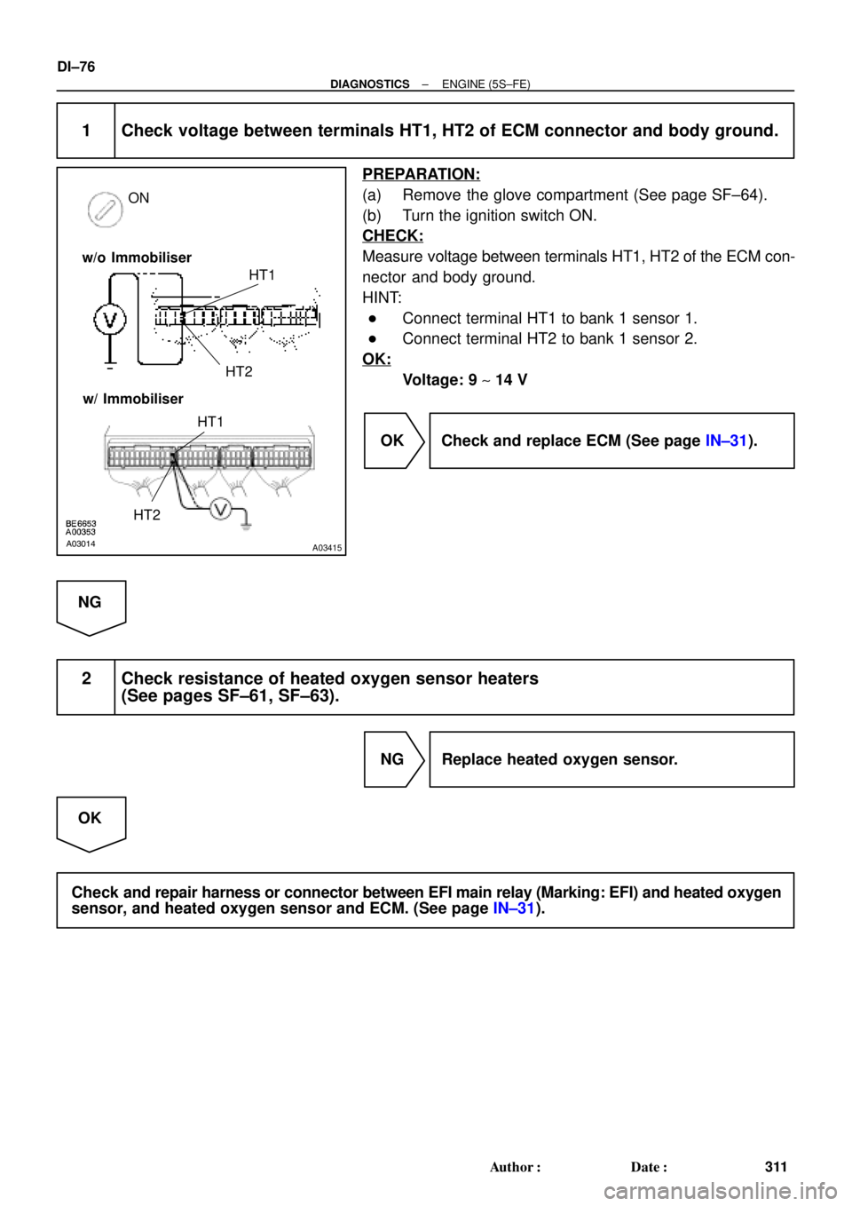
1 Check voltage between terminals HT1, HT2 of ECM connector and body ground.
PREPARATION:
(a) Remove the glove compartment (See page SF±64).
(b) Turn the ignition switch ON.
CHECK:
Measure voltage between terminals HT1, HT2 of the ECM con-
nector and body ground.
HINT:
�Connect terminal HT1 to bank 1 sensor 1.
�Connect terminal HT2 to bank 1 sensor 2.
OK:
Voltage: 9 ~ 14 V
OK Check and replace ECM (See page IN±31).
NG
2 Check resistance of heated oxygen sensor heaters
(See pages SF±61, SF±63).
NG Replace heated oxygen sensor.
OK
Check and repair harness or connector between EFI main relay (Marking: EFI) and heated oxygen
sensor, and heated oxygen sensor and ECM. (See page IN±31).
Page 1318 of 4592
A07551
ECM
J19
J/C
7 From
Battery
B
213
EFI Relay VSV
for EGR
21P-B23
E9EGR
E01
2K2
2J EFI
II4
Engine Room J/B No.2 1B
B-W 9
B-Y
B
2AB-Y
II3
EB
W-B
2F4
6
B-W B-YE815
MREL E107 (*1) (*2)
(*2)
*1: w/o Immobiliser
*2: w/ Immobiliser(*2) (*2)
5B-Y
(*1)From
Ignition SW DI±106
± DIAGNOSTICSENGINE (5S±FE)
341 Author�: Date�:
WIRING DIAGRAM
Page 1335 of 4592

A07552
3
2
1Y
P
BRECM
1
1
7
9
22 J19
J/C
8
E8
E8
EBE8
E01 E9
E8
EJ/C
J28
J27
10
1V
6
2F From
BatteryB±Y VSV
for EVAP
2V±W
VSV for Vapor
Pressure
Sensor
9
Engine Room J/B No.2 B±Y
EFI II3
53
B±Y
VC
PTNK
E2
EVP
TPC5 V
E1
E01
2J 2A
2K
2
*1: w/o Immobiliser
*2: w/ Immobiliser
(*1) (*2)
MREL(*2)
E8
8
E9
3
E8
16
E10
7 Y Y Vapor Pressure Sensor
P P
BR BR
E
ID1 ID1
1
V V
B±Y
B±W B±W
II4 II4
5
ID1
ID1
ID1
6 5
237
8
II4 II4
II2
(*1) (*2)(*1) (*2)
W±B
B±Y12
BB
B±Y
12
7 4
EFI Relay J27 J27B±Y
B
BJ/C
(*2) (*2)
B±R(*1)From
Ignition SW
± DIAGNOSTICSENGINE (5S±FE)
DI±123
358 Author�: Date�:
WIRING DIAGRAM
INSPECTION PROCEDURE
HINT:
�If DTC P0441 (Evaporative Emission Control System Incorrect Purge Flow), P0446 (Evaporative
Emission Control System Vent Control Malfunction), P0450 (Evaporative Emission Control System
Pressure Sensor Malfunction) or P0451 is output after DTC P0440 (Evaporative Emission Control Sys-
tem Malfunction), first troubleshoot DTC P0441, P0446, P0450 or P0451. If no malfunction is detected,
troubleshoot DTC P0440 next.
�Ask the customer whether, after the MIL came on, the customer found the fuel tank cap loose and tight-
ened it. Also ask the customer whether the fuel tank cap was loose when refuelling. If the fuel tank cap
was not loose, it was the cause of the DTC. If the fuel tank cap was not loose or if the customer was
not sure if it was loose, troubleshoot according to the following procedure.
�Read freeze frame data using TOYOTA hand±held tester or OBD II scan tool. Because freeze frame
records the engine conditions when the malfunction is detected, when troubleshooting it is useful for
determining whether the vehicle was running or stopped, the engine warmed up or not, the air±fuel
ratio lean or rich, etc. at the time of the malfunction.
�When the ENGINE RUN TIME in the freeze frame data is less than 200 seconds, carefully check the
VSV for EVAP, charcoal canister and vapor pressure sensor.
Page 1345 of 4592
± DIAGNOSTICSENGINE (5S±FE)
DI±133
368 Author�: Date�:
7 Check vacuum hose between intake manifold and VSV for EVAP, and VSV for
EVAP and charcoal canister.
CHECK:
(a) Check that the vacuum hose is connected correctly.
(b) Check the vacuum hose for looseness and disconnection.
(c) Check the vacuum hose for cracks, hole, damage and blockage.
NG Repair or replace.
OK
8 Check operation of VSV for EVAP (See page SF±45).
OK Go to step 9.
NG
Replace VSV, charcoal canister and then clean the vacuum hose between throttle body and VSV
for EVAP, and VSV for EVAP and charcoal canister.
9 Check for open and short in harness and connector between EFI main relay
(Marking: EFI) and VSV for EVAP, and VSV for EVAP and ECM
(See page IN±31).
NG Repair or replace harness or connector.
OK
Check and replace ECM (See page IN±31).
Page 1347 of 4592

E2 (±)
E2 (±) w/o Immobiliser
w/ Immobiliser
PTNK (+)
Vapor Pressure Sensor
± DIAGNOSTICSENGINE (5S±FE)
DI±135
370 Author�: Date�:
12 Check for ope")
A03018
A03280
A03421
VSV Connector for
PTNK (+)
E2 (±)
E2 (±) w/o Immobiliser
w/ Immobiliser
PTNK (+)
Vapor Pressure Sensor
± DIAGNOSTICSENGINE (5S±FE)
DI±135
370 Author�: Date�:
12 Check for open and short in harness and connector between EFI main relay
(Marking: EFI) and VSV for vapor pressure sensor, and VSV for vapor pressure
sensor and ECM (See page IN±31).
NG Repair or replace harness or connector.
OK
Check and replace ECM (See page IN±31).
13 When VSV connector for vapor pressure sensor is disconnected and VSV for
EVAP is ON, measure voltage between terminals PTNK and E2 of ECM connector.
PREPARATION:
(a) Remove the glove compartment (See page SF±64).
(b) Connect the TOYOTA hand±held tester to the DLC3.
(c) Disconnect the VSV connector for the vapor pressure
sensor.
(d) Select the ACTIVE TEST mode on the TOYOTA hand±
held tester.
(e) Start the engine.
CHECK:
Measure voltage between terminals PTNK and E2 of the ECM
connector using the TOYOTA hand±held tester when the VSV
for the EVAP is ON.
OK:
Voltage: 2.0 V or less
OK Go to step 15.
NG
 (*2)
(*2)
*1: w")