Page 3316 of 4592

SS0AH±04
SS±6
± SERVICE SPECIFICATIONSSFI
TORQUE SPECIFICATION
Part tightenedN´mkgf´cmft´lbf
Fuel line for union for fuel inlet coupler
for others42
28428
28631
21
Fuel filter x Drain plug10.811 08
Fuel filter x Fuel filter bracket21.521916
Fuel filter x Union3131623
Oil separator x Fuel pressure regulator24.525018
Fuel pressure regulator x Bracket2020015
Fuel pressure regulator bracket x Body for 10 mm head bolt
for 12 mm head bolt9.9
19.6100
20088 in.´lbf
14
Fuel relief pipe x Fuel pressure regulator4242831
Delivery pipe x cylinder head1313010
Fuel tank band x Fuel tank frame5253038
Rear side plate x Front side plate1001,02074
Union x Fuel shutoff valve for fuel pipe filter pipe
for others31
18316
18423
13
Fuel tank bracket x Fuel tank valve case8.28473 in.´lbf
Fuel tank valve cover x Fuel tank valve case8.28473 in.´lbf
Fuel tank frame x Body60.261444
Performance rod x Body39.240029
Performance rod x Fuel tank band18.118513
Fuel shutoff valve core x Delivery pipe3535726
Fuel shutoff valve coil x Core1515311
Fuel temperature sensor x Delivery pipe20.420815
Fuel pressure sensor x Delivery pipe24.625118
Fuel pressure sensor x Fuel main pipe68.670051
Fuel inlet hose x Fuel pressure regulator9.910088 in.´lbf
Page 3325 of 4592
SFI SYSTEM
SF±3
1436 Author�: Date�:
(b) When connecting the union bolt on t")
S05523
New Gasket
FI1654
SST
30 cm Fulcrum Length
FI0420
Injector
GrommetO±Ring
Delivery PipeCORRECT
WRONG
± SFI (5S±FE)SFI SYSTEM
SF±3
1436 Author�: Date�:
(b) When connecting the union bolt on the high pressure pipe
union, observe these procedures:
(1) Always use 2 new gaskets.
(2) Tighten the union bolt by hand.
(3) Tighten the union bolt to the specified torque.
Torque: 29 N´m (300 kgf´cm, 21 ft´lbf)
(c) When connecting the flare nut on the high pressure pipe
union, observe these procedures:
(1) Apply a light coat of engine oil to the flare nut, and
tighten the flare nut by hand.
(2) Using SST, tighten the flare nut to specified torque.
SST 09631±22020
NOTICE:
Do not rotate the fuel pipe, when tightening the flare nut.
Torque: 28 N´m (285 kgf´cm, 21 ft´lbf) for using SST
HINT:
Use a torque wrench with a fulcrum length of 30 cm (11.81 in.).
(d) Observe these precautions when removing and installing
the injectors.
(1) Never reuse the O±ring.
(2) When placing a new O±ring on the injector, take
care not to damage it in any way.
(3) Coat a new O±ring with spindle oil or gasoline be-
fore installing±never use engine, gear or brake oil.
Page 3391 of 4592
SFI SYSTEM
SF±3
1502 Author�: Date�:
(b) When connecting the union bolt on th")
S05054
New Gasket
FI1654
Fulcrum Length
30 cm
SST
FI6372 FI6372
New O±Ring
Grommet
InjectorCORRECT
WRONG
± SFI (1MZ±FE)SFI SYSTEM
SF±3
1502 Author�: Date�:
(b) When connecting the union bolt on the high pressure pipe
union, observe these procedures:
(1) Always use 2 new gaskets.
(2) Tighten the union bolt by hand.
(3) Tighten the union bolt to the specified torque.
Torque: 32.5 N´m (330 kgf´cm, 24 ft´lbf)
(c) When connecting the flare nut on the high pressure pipe
union, observe these procedures:
(1) Apply a light coat of engine oil to the flare nut, and
tighten the flare nut by hand.
(2) Using SST, tighten the flare nut to specified torque.
SST 09631±22020
NOTICE:
Do not rotate the fuel pipe, when tightening the flare nut.
Torque: 28 N´m (285 kgf´cm, 21 ft´lbf) for using SST
HINT:
Use a torque wrench with a fulcrum length of 30 cm (11.81 in.).
(d) Observe these precautions when removing and installing
the injectors.
(1) Never reuse the O±ring.
(2) When placing a new O±ring on the injector, take
care not to damage it in any way.
(3) Coat a new O±ring with spindle oil or gasoline be-
fore installing±never use engine, gear or brake oil.
Page 3396 of 4592
FUEL PUMP
1507 Author�: Date�:
(p) After checking fuel pressure, disconnect the negative (±)
terminal cable")
S05351
S06086
Fuel Hose
Clamp
S04508
Ohmmeter
4 5
S04509
4 5
Battery SF±8
± SFI (1MZ±FE)FUEL PUMP
1507 Author�: Date�:
(p) After checking fuel pressure, disconnect the negative (±)
terminal cable from the battery and carefully remove the
SST and fuel tube connector to prevent gasoline from
splashing.
SST 09268±41047, 09268±41250, 09268±45012
(q) Reconnect the No.1 fuel pipe (fuel tube connector).
CAUTION:
Perform connecting operations of the fuel tube connector
(quick type) after observing the precautions.
(See page SF±1)
(r) Surely install the fuel hose clamp to the fuel filter with
ºclickº sound.
(s) After installing the clamp, check that the clamp is fixed by
pulling up the clamp.
(t) Reconnect the negative (±) terminal cable to the battery.
(u) Check for fuel leaks.
3. REMOVE REAR SEAT CUSHION
4. REMOVE FLOOR SERVICE HOLE COVER
5. DISCONNECT FUEL PUMP & SENDER GAUGE
CONNECTOR
6. INSPECT FUEL PUMP RESISTANCE
Using an ohmmeter, measure the resistance between terminals
4 and 5.
Resistance: 0.2 ± 3.0 W at 20°C (68°F)
If the resistance is not as specified, replace the fuel pump.
7. INSPECT FUEL PUMP OPERATION
Connect the positive (+) lead from the battery to terminal 4 of
the connector, and the negative (±) lead to terminal 5. Check
that the fuel pump operates.
NOTICE:
�These tests must be done quickly (within 10 seconds)
to prevent the coil burning out.
�Keep the fuel pump as far away from the battery as
possible.
�Always do the switching at the battery side.
Page 3482 of 4592
B01240
SST
B01241
ST±16
± STARTING (5S±FE)STARTER
1723 Author�: Date�: �
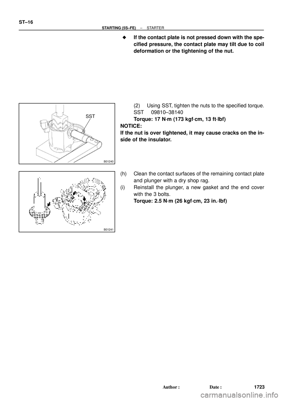
If the contact plate is not pressed down with the spe-
cified pressure, the contact plate may tilt due to coil
deformation or the tightening of the nut.
(2) Using SST, tighten the nuts to the specified torque.
SST 09810±38140
Torque: 17 N´m (173 kgf´cm, 13 ft´lbf)
NOTICE:
If the nut is over tightened, it may cause cracks on the in-
side of the insulator.
(h) Clean the contact surfaces of the remaining contact plate
and plunger with a dry shop rag.
(i) Reinstall the plunger, a new gasket and the end cover
with the 3 bolts.
Torque: 2.5 N´m (26 kgf´cm, 23 in.´lbf)
Page 3502 of 4592
B01240
SST
B01241
ST±16
± STARTING (1MZ±FE)STARTER
1743 Author�: Date�: �
If the contact plate is not pressed down with the spe-
cified pressure, the contact plate may tilt due to coil
deformation or the tightening of the nut.
(2) Using SST, tighten the nuts to the specified torque.
SST 09810±38140
Torque: 17 N´m (173 kgf´cm, 13 ft´lbf)
NOTICE:
If the nut is over tightened, it may cause cracks on the in-
side of the insulator.
(h) Clean the contact surfaces of the remaining contact plate
and plunger with a dry shop rag.
(i) Reinstall the plunger, new gasket and end cover with the
3 bolts.
Torque: 2.5 N´m (26 kgf´cm, 23 in.´lbf)
Page 3513 of 4592

Z15498
Oil
PS Gear
Closed
SSTPS Vane
Pump Reservoir
Z15499
Oil
PS Gear
SSTPS Vane
Pump Reservoir
Open
Z15500
Oil
PS Gear
SSTPS Vane
Pump Reservoir
Lock Position
± STEERINGPOWER STEERING FLUID
SR±7
2102 Author�: Date�:
(f) With the engine idling, close the valve of the SST and ob-
serve the reading on the SST.
Minimum fluid pressure:
7,845 kPa (80 kgf´cm
2, 1,138 psi)
NOTICE:
�Do not keep the valve closed for more than 10 se-
conds.
�Do not let the fluid temperature become too high.
(g) With the engine idling, open the valve fully.
(h) Measure the fluid pressure at engine speeds of 1,000 rpm
and 3,000 rpm.
Difference fluid pressure:
490 kPa (5 kgf´cm
2, 71 psi) or less
NOTICE:
Do not turn the steering wheel.
(i) With the engine idling and valve fully opened, turn the
steering wheel to full lock.
Minimum fluid pressure:
7,845 kPa (80 kgf´cm
2, 1,138 psi)
NOTICE:
�Do not maintain lock position for more than 10 se-
conds.
�Do not let the fluid temperature become too high.
(j) Disconnect the SST.
(k) Connect the pressure feed tube.
(See page SR±28)
(l) Bleed the power steering system.
(See page SR±4)
Page 3524 of 4592
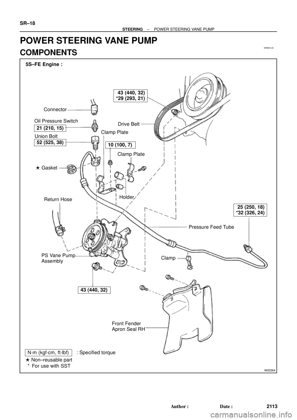
SR06N±03
W03364
Pressure Feed Tube Connector
Oil Pressure Switch
Drive Belt
Clamp Plate
Clamp Plate
Holder
Clamp
Front Fender
Apron Seal RH PS Vane Pump
AssemblyReturn Hose � Gasket Union Bolt 5S±FE Engine :
21 (210, 15)
43 (440, 32)
*29 (293, 21)
10 (100, 7)
25 (250, 18)
*32 (326, 24)
43 (440, 32)
52 (525, 38)
N´m (kgf´cm, ft´lbf) : Specified torque
� Non±reusable part
For use with SST * SR±18
± STEERINGPOWER STEERING VANE PUMP
2113 Author�: Date�:
POWER STEERING VANE PUMP
COMPONENTS