Page 2708 of 4592
CYLINDER HEAD
EM±43
1329 Author�: Date�:
INSPECTION
1. CLEAN TOP SURFACES OF PISTONS AND
CYLINDER BLOCK
(a) Turn the cranksh")
EM0YP±01
P12689
P12492
P12700
P12701
P12703
± ENGINE MECHANICAL (1MZ±FE)CYLINDER HEAD
EM±43
1329 Author�: Date�:
INSPECTION
1. CLEAN TOP SURFACES OF PISTONS AND
CYLINDER BLOCK
(a) Turn the crankshaft, and bring each piston to top dead
center (TDC). Using a gasket scraper, remove all the car-
bon from the piston top surface.
(b) Using a gasket scraper, remove all the gasket material
from the cylinder block surface.
(c) Using compressed air, blow carbon and oil from the bolt
holes.
CAUTION:
Protect your eyes when using high pressure compressed
air.
2. REMOVE GASKET MATERIAL
Using a gasket scraper, remove all the gasket material from the
cylinder block contact surface.
NOTICE:
Be careful not to scratch the cylinder block contact sur-
face.
3. CLEAN COMBUSTION CHAMBERS
Using a wire brush, remove all the carbon from the combustion
chambers.
NOTICE:
Be careful not to scratch the cylinder block contact sur-
face.
4. CLEAN CYLINDER HEADS
Using a soft brush and solvent, thoroughly clean the cylinder
head.
Page 2746 of 4592

No.2 Idler Pulley Bracket
Water Seal Plate
Engine Cool")
EM050±03
A06640
Knock Sensor Connector
Engine Wire Band
Engine WireKnock Sensor
No.2 ECT Switch Connector
Water Inlet Housing
(With Water Inlet)
No.2 Idler Pulley Bracket
Water Seal Plate
Engine Coolant
Drain Union
Oil Filter Union
Oil Filter � Gasket
EGR Cooler
� Gasket
Water Pump
� Crankshaft
Front Oil Seal
Crankshaft
Position Sensor
Connector� Oil Pressure Switch
Oil Pressure Switch
ConnectorA/C Compressor
Housing Bracket
No.1 Oil Pan
x 15 or 17 Oil Pump
� Gasket
� Gasket
Engine Wire
Generator
Drain Plugx 10No.2 Oil Pan Oil Strainer
� Non±reusable part
N´m (kgf´cm, ft´lbf) : Specified torque
Precoated part �
x 8
�
� O±Ring
x 9
9 (90, 78 in.´lbf)
8 (80, 69 in.´lbf)
10mm Head 7.8 (80, 69 in.´lbf)
12mm Head 19.5 (200,14)
39 (400, 29)
28 (290, 21)
14.5 (145, 10)
25 (250, 18)
10mm Head 8 (80, 69 in.´lbf)
12mm Head 19.5 (200,14)
8 (80, 69 in.´lbf)
8 (80, 69 in.´lbf)45 (460, 33)
8 (80, 69 in.´lbf)
or 0 or 0
± ENGINE MECHANICAL (1MZ±FE)CYLINDER BLOCK
EM±81
1367 Author�: Date�:
CYLINDER BLOCK
COMPONENTS
Page 2748 of 4592
EM051±04
S04921
P12946
P18761
P12389
SST
± ENGINE MECHANICAL (1MZ±FE)CYLINDER BLOCK
EM±83
1369 Author�: Date�:
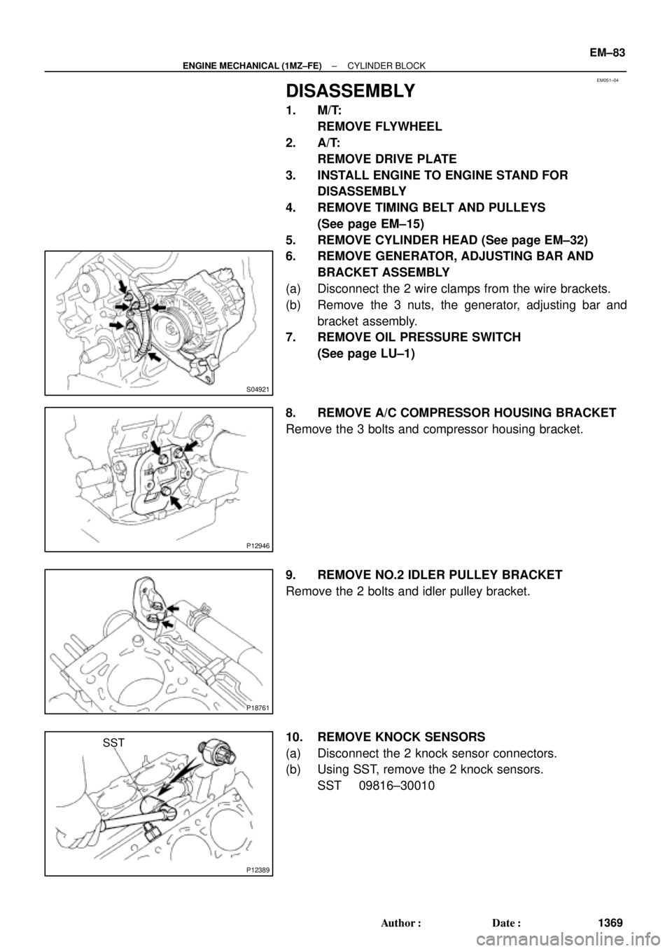
DISASSEMBLY
1. M/T:
REMOVE FLYWHEEL
2. A/T:
REMOVE DRIVE PLATE
3. INSTALL ENGINE TO ENGINE STAND FOR
DISASSEMBLY
4. REMOVE TIMING BELT AND PULLEYS
(See page EM±15)
5. REMOVE CYLINDER HEAD (See page EM±32)
6. REMOVE GENERATOR, ADJUSTING BAR AND
BRACKET ASSEMBLY
(a) Disconnect the 2 wire clamps from the wire brackets.
(b) Remove the 3 nuts, the generator, adjusting bar and
bracket assembly.
7. REMOVE OIL PRESSURE SWITCH
(See page LU±1)
8. REMOVE A/C COMPRESSOR HOUSING BRACKET
Remove the 3 bolts and compressor housing bracket.
9. REMOVE NO.2 IDLER PULLEY BRACKET
Remove the 2 bolts and idler pulley bracket.
10. REMOVE KNOCK SENSORS
(a) Disconnect the 2 knock sensor connectors.
(b) Using SST, remove the 2 knock sensors.
SST 09816±30010
Page 2775 of 4592
P00601
Adhesive
A05416
1
2 34 5
67
8
EM±110
± ENGINE MECHANICAL (1MZ±FE)CYLINDER BLOCK
1396 Author�: Date�:
30. INSTALL OIL PRESSURE SWITCH
(See page LU±1)
31. INSTALL GENERATOR, BRACKET AND
ADJUSTING BAR ASSEMBLY
Torque: 43 N´m (440 kgf´cm, 32 ft´lbf)
32. INSTALL CYLINDER HEAD (See page EM±57)
33. INSTALL TIMING PULLEYS AND BELT
(See page EM±21)
34. REMOVE ENGINE STAND
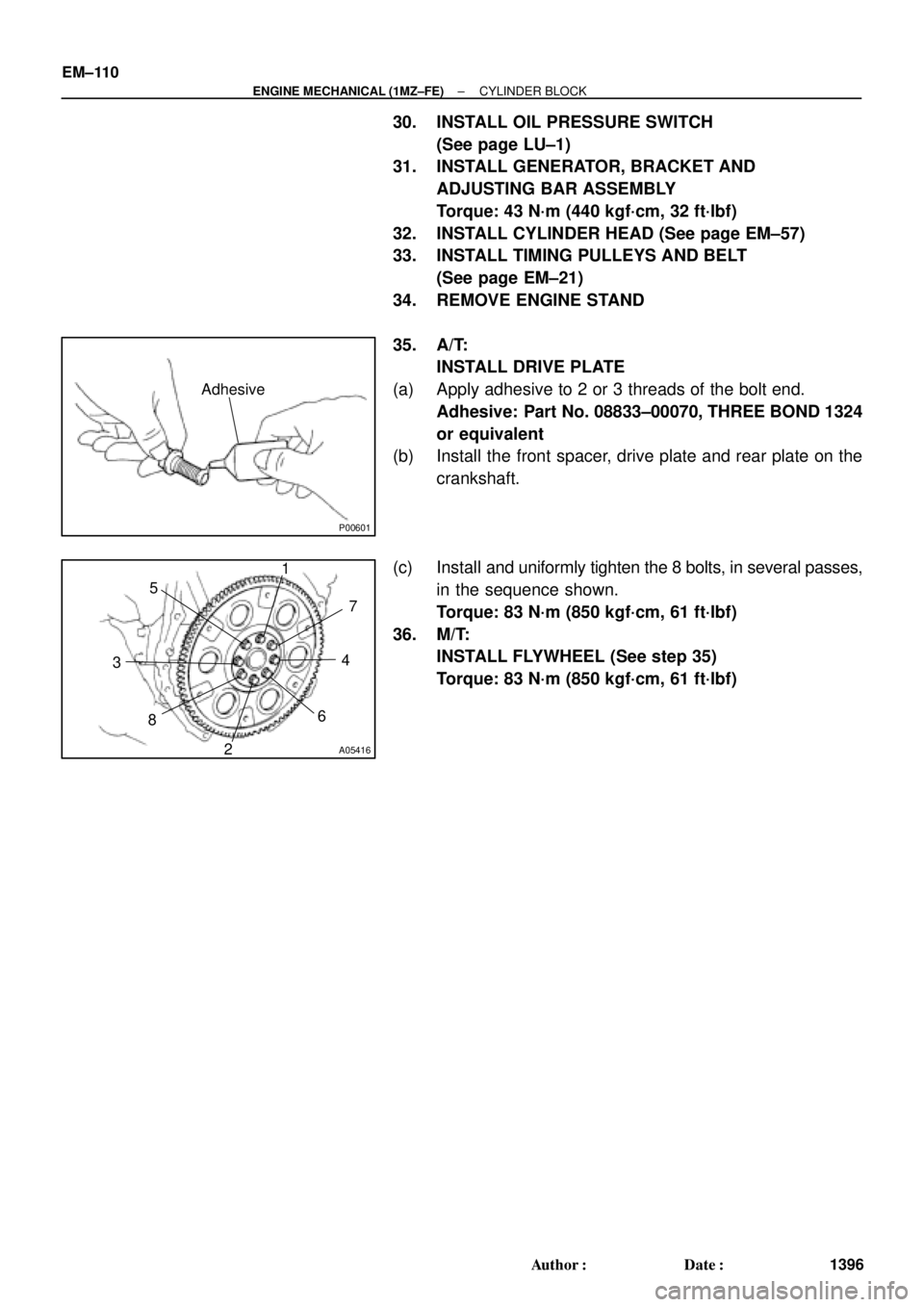
35. A/T:
INSTALL DRIVE PLATE
(a) Apply adhesive to 2 or 3 threads of the bolt end.
Adhesive: Part No. 08833±00070, THREE BOND 1324
or equivalent
(b) Install the front spacer, drive plate and rear plate on the
crankshaft.
(c) Install and uniformly tighten the 8 bolts, in several passes,
in the sequence shown.
Torque: 83 N´m (850 kgf´cm, 61 ft´lbf)
36. M/T:
INSTALL FLYWHEEL (See step 35)
Torque: 83 N´m (850 kgf´cm, 61 ft´lbf)
Page 2780 of 4592
IGNITION SYSTEM
IG±3
1685 Author�: Date�:
(c) Using a 16 mm plug wrench, remove the 4 spark plugs.
(d) Visually check the sp")
S05308
16 mm Plug
Wrench
P20584
IG0152
B06373
Ohmmeter
± IGNITION (5S±FE)IGNITION SYSTEM
IG±3
1685 Author�: Date�:
(c) Using a 16 mm plug wrench, remove the 4 spark plugs.
(d) Visually check the spark plug for thread damage and insu-
lator damage.
If abnormal, replace the spark plug.
Recommended spark plug:
DENSO madePK20TR11
NGK madeBKR6EKPB11
(e) Inspect the electrode gaps.
Maximum electrode gap for used spark plug:
1.3 mm (0.051 in.)
If the gap is greater than maximum, replace the spark plug.
Correct electrode gap for new spark plug:
1.1 mm (0.043 in.)
NOTICE:
If adjusting the gap of a new spark plug, bend only the base
of the ground electrode. Do not touch the tip. Never attempt
to adjust the gap on the used plug.
(f) Clean the spark plugs.
If the electrode has traces of wet carbon, allow it to dry and then
clean with a spark plug cleaner.
Air pressure: Below 588 kPa (6 kgf/cm
2, 85 psi)
Duration: 20 seconds or less
HINT:
If there are traces of oil, remove it with gasoline before using the
spark plug cleaner.
(g) Using a 16 mm plug wrench, install the 4 spark plugs.
Torque: 18 N´m (180 kgf´cm, 13 ft´lbf)
(h) Reconnect the high±tension cords from the spark plugs.
4. INSPECT IGNITION COILS WITH IGNITERS
(a) Disconnect the high±tension cords from the ignition coils.
(b) Inspect the secondary coil resistance.
Using an ohmmeter, measure the resistance between the
high±tension terminals.
Secondary coil resistance:
Cold9.7 ± 16.7 kW
Hot12.4 ± 19.6 kW
Page 2795 of 4592
IGNITION SYSTEM
IG±5
1699 Author�: Date�:
(e) Using a 16 mm plug wrench, remove the 6 spark plugs
from")
P13225
16 mm Plug
Wrench
P25746
DENSO PK20TR11 NGK BKR6EKPB11
P20584
IG0152
± IGNITION (1MZ±FE)IGNITION SYSTEM
IG±5
1699 Author�: Date�:
(e) Using a 16 mm plug wrench, remove the 6 spark plugs
from the RH and LH cylinder heads.
(f) Check the spark plug for thread damage and insulator
damage.
If abnormal, replace the spark plug.
Recommended spark plug:
DENSO madePK20TR11
NGK madeBKR6EKPB11
(g) Inspect the electrode gaps.
Maximum electrode gap for used spark plug:
1.3 mm (0.051 in.)
If the gap is greater than maximum, replace the spark plug.
Correct electrode gap for new spark plug:
1.1 mm (0.043 in.)
NOTICE:
If adjusting the gap of a new spark plug, bend only the base
of the ground electrode. Do not touch the tip. Never attempt
to adjust the gap on the used plug.
(h) Clean the spark plugs.
If the electrode has traces of wet carbon, allow it to dry and then
clean with a spark plug cleaner.
Air pressure: Below 588 kPa (6 kgf/cm
2, 85 psi)
Duration: 20 seconds or less
HINT:
If there are traces of oil, remove it with gasoline before using the
spark plug cleaner.
(i) Using a 16 mm plug wrench, install the 6 spark plugs to
the RH and LH cylinder heads.
Torque: 18 N´m (180 kgf´cm, 13 ft´lbf)
(j) Install the ignition coils.
(k) Install the high±tension cords set. (See step 2)
4. INSPECT IGNITION COILS
(a) Disconnect the high±tension cords from the ignition coils.
(b) Disconnect the ignition coil connectors.
Page 2888 of 4592
 :
TEMPERATURE RANGE ANTICIPATED BEFORE NEXT OIL CHANGE 10W ± 30
5W ± 30 PREFERRED
±20
°C °F020406080
±29 ±18 ±7 4 16 27100
38
LU03H±03
S05317
Curved
Tip
Ins")
B00319
Recommended Viscosity (SAE) :
TEMPERATURE RANGE ANTICIPATED BEFORE NEXT OIL CHANGE 10W ± 30
5W ± 30 PREFERRED
±20
°C °F020406080
±29 ±18 ±7 4 16 27100
38
LU03H±03
S05317
Curved
Tip
Insert
S05298
Oil Pressure Gauge
P13638
Adhesive
± LUBRICATION (5S±FE)OIL AND FILTER
LU±1
1647 Author�: Date�:
OIL AND FILTER
INSPECTION
1. CHECK ENGINE OIL QUALITY
Check the oil for deterioration, entry of water, discoloring or thin-
ning.
If the quality is visibly poor, replace the oil.
Oil grade:
API grade SJ, Energy±Conserving or ILSAC multi-
grade engine oil. SAE 5W±30 is the best choice for
your vehicle, for good fuel economy, and good start-
ing in cold weather.
2. CHECK ENGINE OIL LEVEL
After warming up the engine and then 5 minutes after the en-
gine stop, oil level should be between ºLº and ºFº of the dipstick.
If low, check for leakage and add oil up to ºFº mark.
NOTICE:
�Do not fill with engine oil above the ºFº mark.
�When inserting the oil dipstick, insert the curved tip
of the dipstick facing the same direction as the curve
of the guide.
�If the dipstick gets caught while inserting it, do not
force it in. Reconfirm the direction of the dipstick.
3. REMOVE OIL PRESSURE SWITCH AND INSTALL OIL
PRESSURE GAUGE
4. WARM UP ENGINE
Allow the engine to warm up to normal operating temperature.
5. CHECK OIL PRESSURE
Oil pressure:
At idle29 kPa (0.3 kgf/cm2, 4.3 psi) or more
At 3,000 rpm245 ± 490 kPa (2.5 ± 5.0 kgf/cm2, 36 ± 71 psi)
6. REMOVE OIL PRESSURE GAUGE AND REINSTALL
OIL PRESSURE SWITCH
(a) Remove the oil pressure gauge.
(b) Apply adhesive to 2 or 3 threads of the oil pressure switch.
Adhesive:
Part No. 08833±00080, THREE BOND 1344, LOCTITE
242 or equivalent
(c) Reinstall the oil pressure switch.
7. START ENGINE AND CHECK FOR OIL LEAKS
Page 2906 of 4592
:
TEMPERATURE RANGE ANTICIPATED BEFORE NEXT OIL CHANGE10W±30
5W±30 PREFERRED°C °F
±20
±290
±1820
±740
460
1680
27100
38
LU0FR±01
P25173SST
P25171
Oil Pressur")
B00319
Recommended Viscosity (SAE):
TEMPERATURE RANGE ANTICIPATED BEFORE NEXT OIL CHANGE10W±30
5W±30 PREFERRED°C °F
±20
±290
±1820
±740
460
1680
27100
38
LU0FR±01
P25173SST
P25171
Oil Pressure Gauge
± LUBRICATION (1MZ±FE)OIL AND FILTER
LU±1
1665 Author�: Date�:
OIL AND FILTER
INSPECTION
1. CHECK ENGINE OIL QUALITY
Check the oil for deterioration, entry of water, discoloring or thin-
ning.
If the quality is visibly poor, replace the oil.
Oil grade:
API grade SJ, Energy±Conserving or ILSAC multi-
grade engine oil.
SAE 5W ± 30 is the best choice for your vehicle, for
good fuel economy, and good starting in cold weath-
er.
2. CHECK ENGINE OIL LEVEL
After warm up the engine and then 5 minutes after the engine
stop, oil level should be between the low level and full level
marks on the dipstick.
If low, check for leakage and add oil up to the full level mark.
NOTICE:
Do not fill with engine oil above the full level mark.
3. REMOVE OIL PRESSURE SWITCH, AND INSTALL
OIL PRESSURE GAUGE
(a) Using SST, remove the oil pressure switch.
SST 09816±30010
(b) Install the oil pressure gauge.
4. WARM UP ENGINE
Allow the engine to warm up to normal operating temperature.
5. CHECK OIL PRESSURE
Oil pressure:
At idle29 kPa (0.3 kgf/cm2, 4.3 psi) or more
At 3,000 rpm294 ± 539 kPa (3.0 ± 5.5 kgf/cm2, 43 ± 78 psi)