Page 2609 of 4592
CYLINDER HEAD
1230 Author�: Date�:")
P13638
Adhesive
S05962
Z09141
California
Except California New O±RingNew Insulator
New GrommetNew O±Ring
New GrommetNew
O±Ring EM±58
± ENGINE MECHANICAL (5S±FE)CYLINDER HEAD
1230 Author�: Date�:
9. INSTALL OIL PRESSURE SWITCH
(a) Apply adhesive to 2 or 3 threads.
Adhesive:
Part No. 08833±00080, THREE BOND 1324 or equiva-
lent
(b) Install the oil pressure switch.
10. INSTALL ENGINE HANGERS AND GENERATOR
BRACKET
(a) Install the generator bracket and RH engine hanger as-
sembly with the 3 bolts.
Torque: 42 N´m (425 kgf´cm, 31 ft´lbf)
(b) Install the LH engine hanger with the bolt.
Torque: 25 N´m (250 kgf´cm, 18 ft´lbf)
11. INSTALL NO.3 TIMING BELT COVER
Install the timing belt cover with the 3 bolts.
Torque: 7.8 N´m (80 kgf´cm, 69 in.´lbf)
12. TEMPORARILY INSTALL NO.1 IDLER PULLEY AND
TENSION SPRING (See page EM±23)
13. INSTALL CAMSHAFT TIMING PULLEY
(See page EM±23)
14. CONNECT TIMING BELT TO CAMSHAFT TIMING
PULLEY (See page EM±23)
15. INSTALL INJECTORS AND DELIVERY PIPE
(a) California:
Install a new insulator and grommet to each injector.
(b) Except California:
Install a new grommet to each injector.
(c) California:
Apply a light coat of gasoline onto 2 new O±rings, and
install them to each injector.
(d) Except California:
Apply a light coat of gasoline onto a new O±ring, and
install it to each injector.
Page 2612 of 4592
(c)(d)
± ENGINE MECHANICAL (5S±FE)CYLINDER HEAD
EM±61
1233 Author�: Date�:
18. CONNECT FUEL INLET HOSE TO DELIVERY PIPE
(a) T")
S05982
SST
Fulcrum
Length
A07365
A07363
A07364
Clamp
Connector
A01564(b)(c)(d)
± ENGINE MECHANICAL (5S±FE)CYLINDER HEAD
EM±61
1233 Author�: Date�:
18. CONNECT FUEL INLET HOSE TO DELIVERY PIPE
(a) Temporarily connect the fuel inlet hose with 2 new gas-
kets and fuel pulsation damper.
(b) Using SST, tighten the fuel pulsation damper.
SST 09612±24014 (09617±24011)
Torque:
34 N´m (350 kgf´cm, 25 ft´lbf)
29 N´m (300 kgf´cm, 21 ft´lbf) for use with SST
HINT:
Use a torque wrench with a fulcrum length of 30 cm (1.181 in.).
19. INSTALL ENGINE WIRE
(a) Install the 2 engine wire clamps to the 2 brackets on the
front side of the intake manifold.
(b) Install the engine wire clamp to the bracket on the LH side
of the intake manifold.
20. INSTALL EGR VALVE AND VACUUM MODULATOR
(a) Install a new gasket, the EGR valve, EGR pipe and vacu-
um modulator assembly with the union nut, 2 nuts and
bolt.
Torque:
13.3 N´m (136 kgf´cm, 10 ft´lbf) for nut
61.2 N´m (624 kgf´cm, 45 ft´lbf) for union nut
(b) Install the hose clamp to the bracket on the intake man-
ifold.
(c) Install the VSV for the EGR with the bolt.
(d) Connect the VSV connector for the EGR.
21. INSTALL INTAKE MANIFOLD STAY
Install the intake manifold stay with the bolt and nut.
Torque: 39 N´m (398 kgf´cm, 29 ft´lbf)
22. INSTALL WATER OUTLET
(a) Install a new gasket and the water outlet with the 2 nuts.
Torque: 15 N´m (150 kgf´cm, 11 ft´lbf)
(b) Connect the radiator hose to the water outlet.
(c) Connect the water bypass pipe hose to the water outlet.
(d) Connect the heater water hose to the water outlet.
(e) Connect the ECT sensor connector.
(f) Connect the ECT sender gauge connector.
23. CONNECT OIL PRESSURE SWITCH CONNECTOR
24. CONNECT NOISE FILTER CONNECTOR
Page 2615 of 4592

EM0YV±01
A02195
Radiator Reservoir Hose
Generator Drive BeltUpper Radiator
Hose
Support BracketFront Exhaust Pipe PS Oil Pressure Switch
ConnectorBattery TrayBattery
PS Pump Drive Belt
PS Pump
Support Stay Upper Radiator Support
Lower Radiator Hose
A/C Compressor
Cylinder Block Insulator
LH Front Fender Apron Seal
Oil Cooler Hose (A/T)
Cruise Control ActuatorEVAP Hose
Air Filter Upper Radiator
Support
EVAP Hose Hood
PCV Hose
Support
Bracket � Gasket
�
� Non±reusable part� Gasket
�Clamp
N´m (kgf´cm, ft´lbf)
62 (630, 46)
56 (570, 41)
�
: Specified torque
Washer Hose
for Windshield
No.1 Electric
Cooling Fan
Connector
ECT Switch
Connector No.2 Electric
Cooling Fan
ConnectorRadiator
Assembly
A/C Compressor
ConnectorLower Radiator
Support
RH Front Fender
Aplon Seal
Cruise
Control
Actuator
Connector
Battery
Hold±Down
ClampAir Cleaner
Case
VSV
Connector
for EVAP
EVAP
Hose
IAT Sensor
Connector
Air
Cleaner
Cap
EM±64
± ENGINE MECHANICAL (5S±FE)ENGINE UNIT
1236 Author�: Date�:
ENGINE UNIT
COMPONENTS
Page 2622 of 4592
S05250
Connector
S05246
S05254
M/T
S04616
A/T
S05247
± ENGINE MECHANICAL (5S±FE)ENGINE UNIT
EM±71
1243 Author�: Date�:
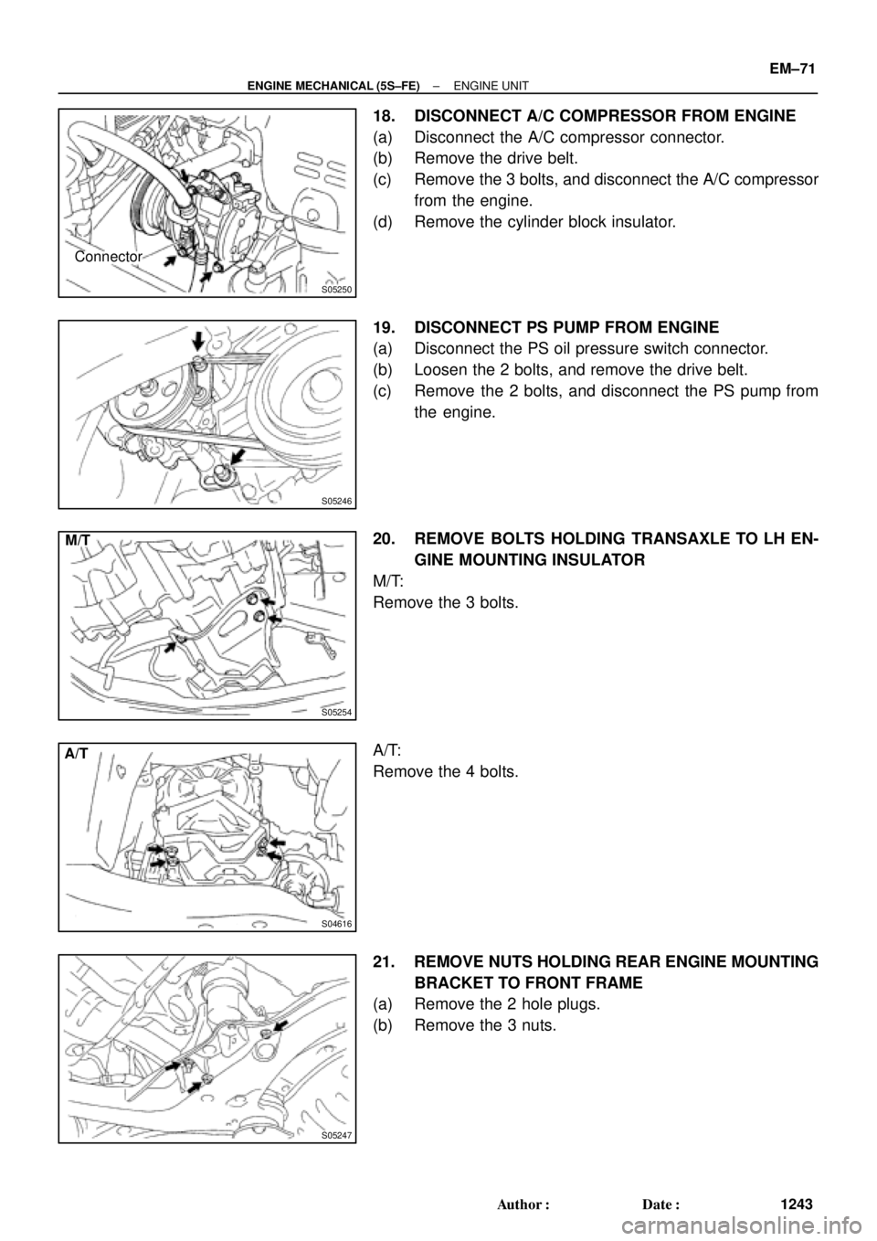
18. DISCONNECT A/C COMPRESSOR FROM ENGINE
(a) Disconnect the A/C compressor connector.
(b) Remove the drive belt.
(c) Remove the 3 bolts, and disconnect the A/C compressor
from the engine.
(d) Remove the cylinder block insulator.
19. DISCONNECT PS PUMP FROM ENGINE
(a) Disconnect the PS oil pressure switch connector.
(b) Loosen the 2 bolts, and remove the drive belt.
(c) Remove the 2 bolts, and disconnect the PS pump from
the engine.
20. REMOVE BOLTS HOLDING TRANSAXLE TO LH EN-
GINE MOUNTING INSULATOR
M/T:
Remove the 3 bolts.
A/T:
Remove the 4 bolts.
21. REMOVE NUTS HOLDING REAR ENGINE MOUNTING
BRACKET TO FRONT FRAME
(a) Remove the 2 hole plugs.
(b) Remove the 3 nuts.
Page 2630 of 4592
ENGINE UNIT
EM±79
1251 Author�: Date�:
A/T:
Install the 4 bolts.
Torque: 64 N´m (650 kgf´cm, 47 ft´lbf)
24. REMOVE ENGINE SLI")
S04616
A/T
S05246
S05250
Connector
S05253
± ENGINE MECHANICAL (5S±FE)ENGINE UNIT
EM±79
1251 Author�: Date�:
A/T:
Install the 4 bolts.
Torque: 64 N´m (650 kgf´cm, 47 ft´lbf)
24. REMOVE ENGINE SLING DEVICE
25. CONNECT TRANSAXLE CONTROL CABLE(S) TO
TRANSAXLE
26. INSTALL PS PUMP
(a) Install the PS pump with the 2 bolts.
Torque: 43 N´m (440 kgf´cm, 32 ft´lbf)
(b) Install the drive belt.
(c) Connect the PS oil pressure switch connector.
27. INSTALL A/C COMPRESSOR
(a) Install the cylinder block insulator and A/C compressor
with the 3 bolts.
Torque: 25.5 N´m (260 kgf´cm, 19 ft´lbf)
(b) Install the drive belt.
(c) Connect the A/C compressor connector.
28. M/T:
INSTALL CLUTCH RELEASE CYLINDER AND TUBE
TO TRANSAXLE
29. M/T:
INSTALL STARTER (See page ST±19)
30. INSTALL DRIVE SHAFTS (See page SA±24)
31. CONNECT ENGINE WIRE TO CABIN
(a) Push in the engine wire through the cowl panel. Install the
grommet.
(b) Connect the 3 engine ECM connectors.
(c) Connect the 3 cowl wire connectors to the connectors on
the bracket.
(d) Install the under cover.
32. CONNECT CONNECTORS, WIRES, CABLES,
CLAMPS AND HOSES
(a) Connect the generator wire.
Page 2668 of 4592
COMPRESSION
EM±3
1289 Author�: Date�:
COMPRESSION
INSPECTION
HINT:
If there is lack of power, excessive oil consumption or poor fuel
ec")
EM04J±03
P19471Compression Gauge
± ENGINE MECHANICAL (1MZ±FE)COMPRESSION
EM±3
1289 Author�: Date�:
COMPRESSION
INSPECTION
HINT:
If there is lack of power, excessive oil consumption or poor fuel
economy, measure the compression pressure.
1. WARM UP AND STOP ENGINE
Allow the engine to warm up to normal operating temperature.
2. REMOVE IGNITION COILS AND HIGH±TENSION
CORDS (See page IG±7)
3. REMOVE SPARK PLUGS
Using a 16 mm plug wrench, remove the 6 spark plugs.
4. CHECK CYLINDER COMPRESSION PRESSURE
(a) Insert a compression gauge into the spark plug hole.
(b) Fully open the throttle.
(c) While cranking the engine, measure the compression
pressure.
HINT:
Always use a fully charged battery to obtain engine speed of
250 rpm or more.
(d) Repeat steps (a) through (c) for each cylinder.
NOTICE:
This measurement must be done in as short a time as pos-
sible.
Compression pressure:
1,500 kPa (15.3 kgf/cm
2, 218 psi)
Minimum pressure: 1,000 kPa (10.2 kgf/cm
2, 145 psi)
Difference between each cylinder:
100 kPa (1.0 kgf/cm
2, 15 psi) or less
(e) If the cylinder compression in 1 or more cylinders is low,
pour a small amount of engine oil into the cylinder through
the spark plug hole and repeat steps (a) through (c) for
cylinders with low compression.
�If adding oil helps the compression, it is likely that
the piston rings and/or cylinder bore are worn or
damaged.
�If pressure stays low, a valve may be sticking or
seating is improper, or there may be leakage past
the gasket.
5. REINSTALL SPARK PLUGS
6. INSTALL IGNITION COILS AND HIGH±TENSION
CORDS (See page IG±8)
Page 2688 of 4592
TIMING BELT
EM±23
1309 Author�: Date�:
7. INSTALL TIMING BELT
NOTICE:
The")
A02338
5th4th3rd
2nd
6th
1st
A05064
1.27 mm
Hexagon
Wrench
A05065
A05066
1.27 mm
Hexagon
Wrench
± ENGINE MECHANICAL (1MZ±FE)TIMING BELT
EM±23
1309 Author�: Date�:
7. INSTALL TIMING BELT
NOTICE:
The engine should be cold.
(a) Remove any oil or water on the pulleys, and keep them
clean.
NOTICE:
Only wipe the pulleys; do not use any cleansing agent.
(b) Face the front mark on the timing belt forward.
(c) Align the installation mark on the timing belt with the tim-
ing mark of the crankshaft timing pulley.
(d) Align the installation marks on the timing belt with the tim-
ing marks of the camshaft timing pulleys.
(e) Install the timing belt in this order:
1st: Crankshaft timing pulley
2nd: Water pump pulley
3rd: LH camshaft timing pulley
4th: No.2 idler pulley
5th: RH camshaft timing pulley
6th: No.1 idler pulley
8. SET TIMING BELT TENSIONER
(a) Using a press, slowly press in the push rod using 981 ±
9,807 N (100 ± 1,000 kgf, 200 ± 2,205 lbf) of pressure.
(b) Align the holes of the push rod and housing, pass a 1.27
mm hexagon wrench through the holes to keep the set-
ting position of the push rod.
(c) Release the press.
(d) Install the dust boot to the tensioner.
9. INSTALL TIMING BELT TENSIONER
(a) Temporarily install the tensioner with the 2 bolts.
(b) Alternately tighten the 2 bolts.
Torque: 27 N´m (280 kgf´cm, 20 ft´lbf)
(c) Remove the 1.27 mm hexagon wrench from the tension-
er.
Page 2693 of 4592

EGR Gas Temperature
Sensor Connector
Water Bypass Hose
A06657
PS Pressure TubeAir Intake Chamber Stay
V±Bank Cover
VSV Connector
for EGR
Engine Wire�Gasket
No.2 EGR Pipe
Throttle Position
Sensor Connector
Vacuum Hose
EGR Valve Position Brake Booster12 (120,9)
39 (400,29)
�Gasket
Sensor Connector
IAC Valve
ConnectorAccelerator Cable
Throttle Cable
Purge Hose
Air Assist Hose Hose Vacuum
�Gasket
VSV Connector for ACIS
Engine Coolant
Reservoir Hose
43 (440,32)
ECT Sender
Gauge Connector
ECT Sensor
Connector
Grand Strap
Connector
15 (150,11)
Water Outlet
15 (150,11)
Water Bypass
Hose
Upper Radiator
Hose
Fuel Inlet Hose
Injector Connector Intake Manifold Assembly�Retainer
Heater Hose
�Gasket Ignition Coil
Connector
� Non±reusable part: Specified torque
N´m (kgf´cm, ft´lbf)
19.5 (200, 14)
No.1 Engine
Hanger
VSV Connector for
EVAP
Ground Cable
PCV Hose Ground Cable
Air Intake Chamber
Assembly
� Gasket
High±Tension Cord Set
Spark PlugIgnition Coil
Water Bypass Hose
Ground Strap
DLC1
EM±28
± ENGINE MECHANICAL (1MZ±FE)CYLINDER HEAD
1314 Author�: Date�: