1999 TOYOTA CAMRY oil pressure
[x] Cancel search: oil pressurePage 4254 of 4592
![TOYOTA CAMRY 1999 Service Repair Manual G
Position of Parts in Engine Compartment
[1MZ±FE]
I 1 Idle Air Control Valve
I 2 Igniter
I 5 Ignition Coil No.1
I 6 Ignition Coil No.2
I 7 Ignition Coil No.3
I 8 Injector No.1
I 9 Injector No.2
I 10 TOYOTA CAMRY 1999 Service Repair Manual G
Position of Parts in Engine Compartment
[1MZ±FE]
I 1 Idle Air Control Valve
I 2 Igniter
I 5 Ignition Coil No.1
I 6 Ignition Coil No.2
I 7 Ignition Coil No.3
I 8 Injector No.1
I 9 Injector No.2
I 10](/manual-img/14/57448/w960_57448-4253.png)
G
Position of Parts in Engine Compartment
[1MZ±FE]
I 1 Idle Air Control Valve
I 2 Igniter
I 5 Ignition Coil No.1
I 6 Ignition Coil No.2
I 7 Ignition Coil No.3
I 8 Injector No.1
I 9 Injector No.2
I 10 Injector No.3
I 11 Injector No.4
I 12 Injector No.5
I 13 Injector No.6
K 1 Knock Sensor 1
K 2 Knock Sensor 2
M 2 Mass Air Flow Meter
N 1 Noise Filter (Ignition)
O 1 Oil Pressure SW
P 1 Park/Neutral Position SW,A/T Indicator Light SW and
Back±Up Light SW
P 2 Power Steering Oil Pressure SWR 1 Radiator Fan Motor
S 1 Starter
S 2 Starter
T 1 Theft Deterrent Horn
T 2 Throttle Position Sensor
V 2 Vehicle Speed Sensor (Combination Meter)
V 3 Vehicle Speed Sensor
(Electronically Controlled Transmission)
V 4 VSV (EGR)
V 5 VSV (EVAP)
V 6 VSV (Intake Air Control)
W 1 Washer Level Warning SW
W 2 Washer Motor
W 3 Water Temp. Sender
W 4 Water Temp. SW No.1
W 5 Water Temp. SW No.2
Page 4256 of 4592
![TOYOTA CAMRY 1999 Service Repair Manual G
Position of Parts in Engine Compartment
[5S±FE]
I 1 Idle Air Control Valve
I 3 Ignition Coil and Igniter No.1
I 4 Ignition Coil and Igniter No.2
I 8 Injector No.1
I 9 Injector No.2
I 10 Injector No TOYOTA CAMRY 1999 Service Repair Manual G
Position of Parts in Engine Compartment
[5S±FE]
I 1 Idle Air Control Valve
I 3 Ignition Coil and Igniter No.1
I 4 Ignition Coil and Igniter No.2
I 8 Injector No.1
I 9 Injector No.2
I 10 Injector No](/manual-img/14/57448/w960_57448-4255.png)
G
Position of Parts in Engine Compartment
[5S±FE]
I 1 Idle Air Control Valve
I 3 Ignition Coil and Igniter No.1
I 4 Ignition Coil and Igniter No.2
I 8 Injector No.1
I 9 Injector No.2
I 10 Injector No.3
I 11 Injector No.4
I 14 Intake Air Temp. Sensor
K 1 Knock Sensor 1
M 1 Manifold Absolute Pressure Sensor
N 1 Noise Filter (Ignition)
O 1 Oil Pressure SW
P 1 Park/Neutral Position SW,A/T Indicator Light SW and
Back±Up Light SW
P 2 Power Steering Oil Pressure SWR 1 Radiator Fan Motor
S 1 Starter
S 2 Starter
T 1 Theft Deterrent Horn
T 2 Throttle Position Sensor
V 2 Vehicle Speed Sensor (Combination Meter)
V 4 VSV (EGR)
V 5 VSV (EVAP)
W 1 Washer Level Warning SW
W 2 Washer Motor
W 3 Water Temp. Sender
W 4 Water Temp. SW No.1
Page 4294 of 4592
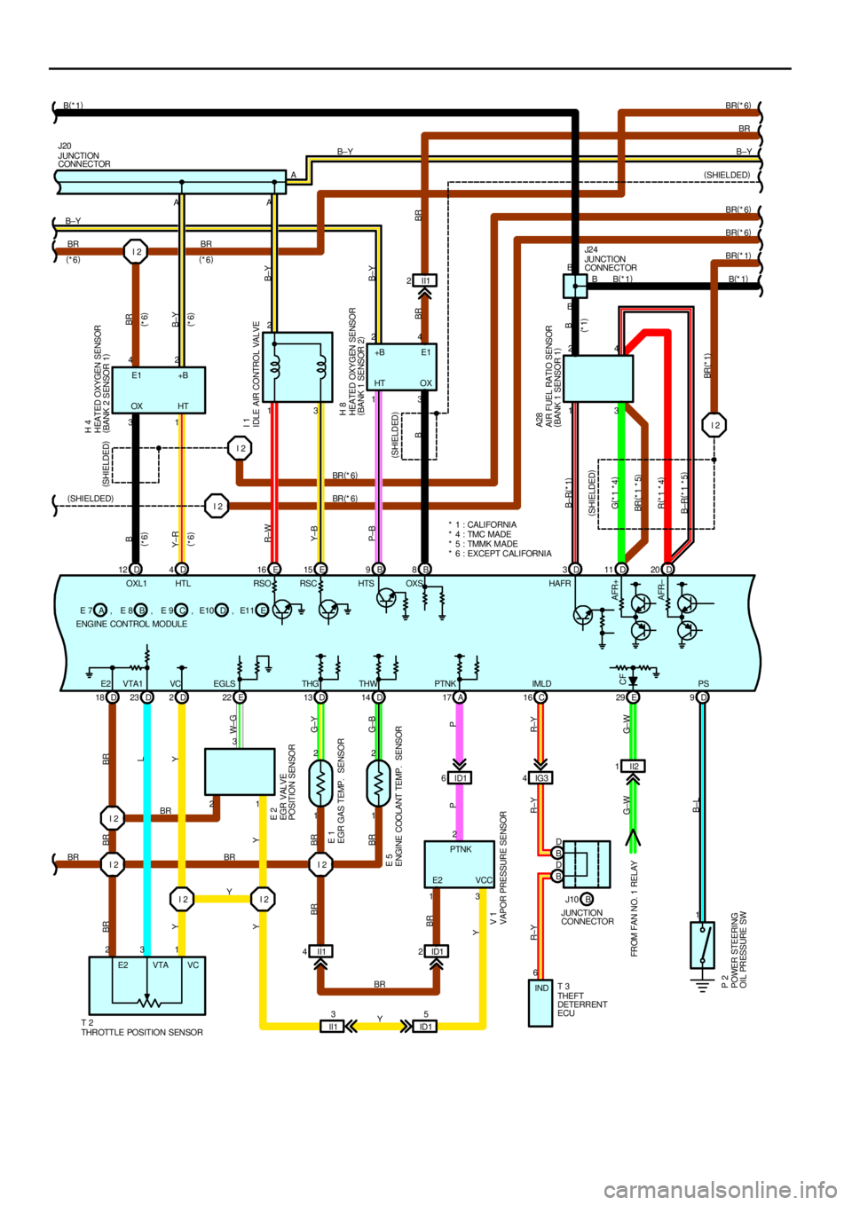
I 2
I 2 I 2
I 2 I 21 2
1 2D 3
D 18 D23 D2D13 D14 A17 E 22D 9
1 II1 2
13 213 1 3 1
3 1 A
2312 34 2 4 2 2 B±Y
BR(
*1) BR
BR Y BR E2 VTA1 VC THG THW PTNKEGLSPS RSO RSC HTS OXS HAFR
B±LW± G
P BR
YY
BR BR
G±B G±Y YL BR BR
Y
R±W
Y±B
P±B
B
B± R(
*1)
BR(
*1)BBR BRB±Y B±Y
B±Y
(
SHIELDED)
(
SHIELDED)(
SHIELDED) Y
A
IDLE AIR CONTROL VALVE
HEATED OXYGEN SENSOR
(
BANK 1 SENSOR 2)
AIR FUEL RATIO SENSOR
(
BANK 1 SENSOR 1) I 1
H 8
A28
JUNCTION
CONNECTOR J20
T 2
THROTTLE POSITION SENSOR
EGR GAS TEMP. SENSOR
ENGINE COOLANT TEMP. SENSOR
VAPOR PRESSURE SENSOREGR VAL VE
POSITION SENSOR
POWER STEERING
OIL PRESSURE SWE 1
E 5
V 1E 2
P 2
ENGINE CONTROL MODULEB E 7 E 8ACE 9 DE10+B E1
HT OX
PTNK
E2 VCC
E2 VTA VC BRI 2ID1 6IG34II2 1 C 16
6
IND
P
R±Y R±Y R±Y
G± W G±W
E 29
FROM FAN NO. 1 RELAYCF
IMLD , , , EE1 1 , B B
B JUNCTION
CONNECTOR J2 4
B(
*1)
THEFT
DETERRENT
ECU T 3 BR B(
*1)
AFR± AFR+
B D
B D
B J10
JUNCTION
CONNECTOR E 16 E15 B9B8D11 D20
G(
*1 *4)
BR(
*1 *5)
R(
*1 *4)
B±R(
*1 *5)
B(
*1) B±Y
D 12 D4 I 2 BR
I 2
I 2 42
31A
OX HTBR
B
Y±RBR
B±Y (
SHIELDED)
(
*6)(
*6)
(
*6)
(
*6) (
*6) (
*6)
OXL1 HTLE1 +B
HEATED OXYGEN SENSOR
(
BANK 2 SENSOR 1) H 4
(
SHIELDED)BR(
*6)
BR(
*6)BR(
*6) BR(
*6)
II13
ID15 II1 4ID12
BRBR
YBR(
*6)
* 1 : CALIFORNIA
* 4 : TMC MADE
* 5 : TMMK MADE
* 6 : EXCEPT CALIFORNIA
(
*1)
Page 4310 of 4592
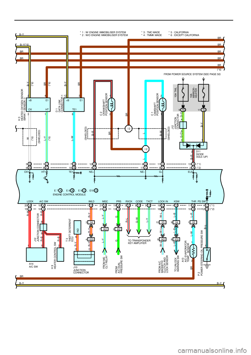
FROM POWER SOURCE SYSTEM (
SEE PAGE 50)
1C 91J11
1 2
2 1
IK2 7IK22
IK2 9II3 10 II21
1 I 2 I 2
A 10 A 20 A21 A19 C19 B11 C4 B 6C8B15 C4C17 C5A2
2 1 B8 1 3
2 A
B4 2123
A
1 3
2 5 1
BR
B±YBR BRB±Y(
*6) B±Y
BR
BR
BR
BR
BR
B±Y PS SW THR LOCK IN PRS MGC TE1
A/C SW LOCK
B±LL±R L±W BRW±L W±L W±LG L±Y
G L±YR±BR±B R±W
R±BW
L±Y
L±W
B±R
BR
L
B±W
G±O G±O
B±YB±Y
BR
B±Y
BR
OX1 HT1 TE1 NE+ NE± G+ E LSE1 +B
10A TAIL
10A
MIRROR±
HEATER (
SHIELDED)
(
SHIELDED) (
SHIELDED)
(
*6) (
*6)(
*6)
(
*6)
L
B±R
(
*6)
DIODE
(
IDLE±UP)
HEATED OXYGEN SENSOR
(
BANK 1 SENSOR 1)
DATA LINK
CONNECTOR 1
CRANKSHAFT
POSITION SENSOR
CAMSHAFT
POSITION SENSOR
JUNCTION
CONNECTORH 3
D 1
C 2
C 1
J12
D11
JUNCTION CONNECTOR
A/C SWHEATER CONTROL SW
A/C EVAPORATOR
TEMP. SENSOR
POWER STEERING OIL PRESSURE SWFROM MG
CLT RELAY
FROM
A/C DUAL
PRESSURE SW
FROM A/ C
MAGNETIC
CLUTCH AND
LOCK SENSORJ12
A13
P 2H 9
A14* 5 : CALIFORNIA
* 6 : EXCEPT CALIFORNIA
BR
ENGINE CONTROL MODULEB E 7 E 8ACE 9 +B E1
OX HT* 1 : W/ ENGINE IMMOBILISER SYSTEM
* 2 : W/O ENGINE IMMOBILISER SYSTEM
, , DE10 , B 5C1B7D12 D6D11 A13(
*1)
(
*2)
IG3 8D 4KSW
L±B L±B L±B
TO UNLOCK
WARN ING SW
A 10 A 15 A21 A13 C18 B10 B12
IG3 4II4 3D 1IMLD
R±Y R±Y R±Y
6
IND R±YTHEFT DETERRENT
ECU T 3
(
*1)
(
*2) D 3D8D9TXCT CODE RXCK
R±L
G± W
L±Y
TO TRANSPONDER
KEY AMPLIFIER
DD
J10
JUNCTION
CONNECTORII4 9 * 3 : TMC MADE
* 4 : TMMK MADE
Page 4506 of 4592
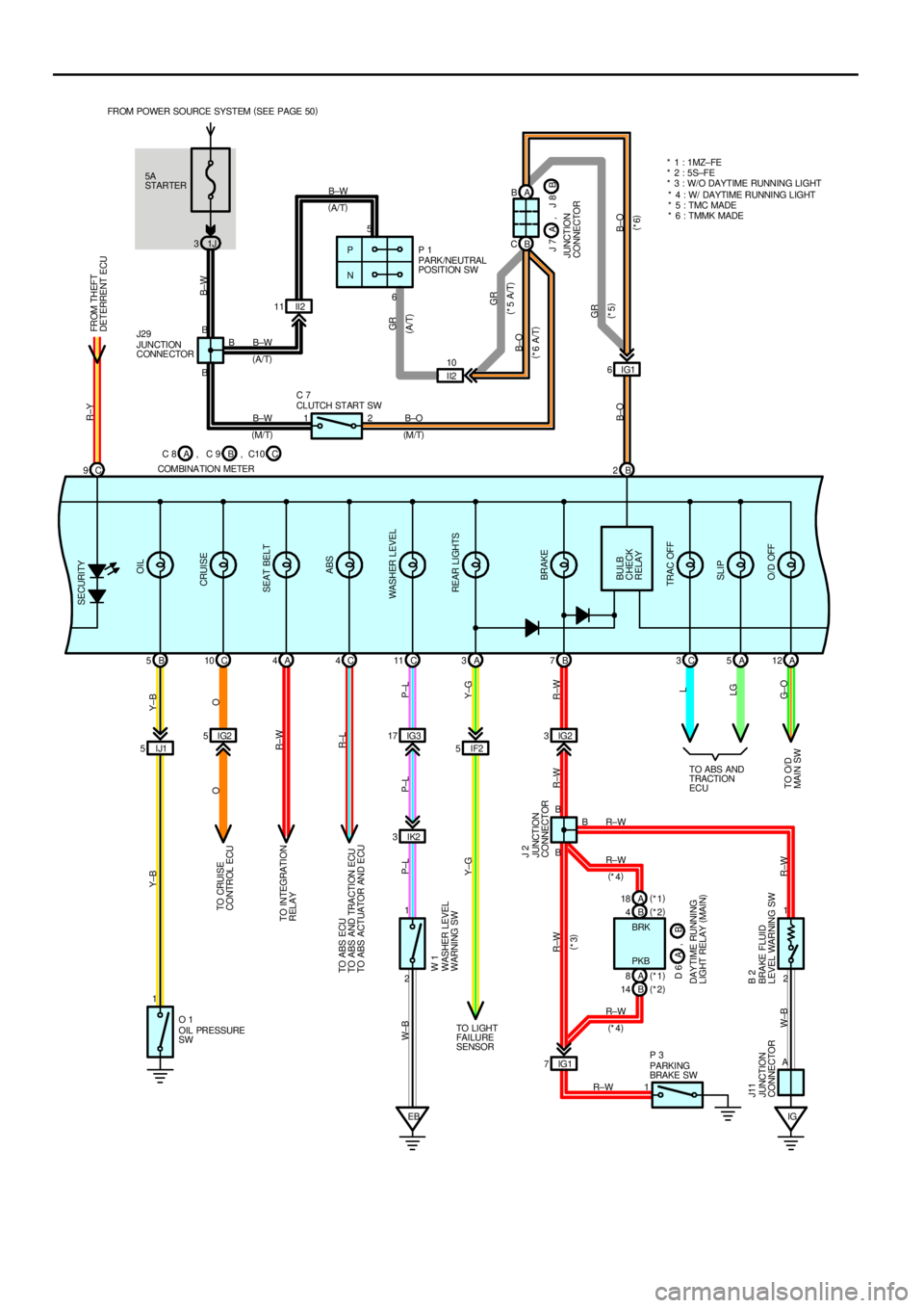
5A
STARTER FROM POWER SOURCE SYSTEM (
SEE PAGE 50)
1J 3
IJ1 5IF2 5 IG2 5IG317 IG23
IK2 3 C 9B 2
B 5C10 A4C4C11 A3B7C3A5A12
EB 2 1 II2 11A B
B C
IG1 6
11
IG1 7
12 1
IG
R±Y
B±W
GR
B±O Y±B Y±B
O O
R±W
R±L
P±L
Y±G P±L P±L W±B
Y±G
R±W R±W R±W
R±W W±B
B±W
B±WB±W
B±O
R±W
R±W R±W
R±W PARK /NEUTRAL
POSITION SW P 1
OIL PRESSURE
SW O 1
PARKING
BRAKE SW P 3 CLUTCH START SW C 7
WASHER LEVEL
WARNING SW W 1
JUNCTION
CONNECTOR J 2
BRAKE FLUID
LEVEL WARNING SW B 2
JUNCTION
CONNECTOR J11L
LG
G± O
B5
B B6
2B B
BFROM THEFT
DETERRENT ECU SECURITY
OIL
CRUISE
SEAT BELT
ABS
WASHER LEVEL
REAR LIGHTS
BRAKE
BULB
CHECK
RELAY
TRAC OFF
SLIP
O/D OFF
(
A/T)
(
M/T) JUNCTION
CONNE CTOR J29
(
M/T) (
A/T)
P
N
(
*5)
(
*6) (
*3)
(
*4)
(
*4)PKB BRK
A
TO CRUISE
CONTROL ECU
TO INTEGRATION
RELAY
TO ABS ECU
TO ABS AND TRACTION ECU
TO ABS ACTUATOR AND ECU
TO LI GHT
FAI LURE
SENSORTO ABS AND
TRACTION
ECU
GR
(
A/T)
II2 10
GR
B±O
B±O(
*5 A/T)
(
*6 A/T)
TO O/D
MAIN SWJ 7
JUNCTION
CONNECTORB A, J 8
C 8
COMBINA TION METERB A, C 9 C, C10* 1 : 1 MZ± FE
* 2 : 5S±FE
* 3 : W/O DAYTIME RUNNING LIGHT
* 4 : W/ DAYTIME RUNNING LIGHT
* 5 : TMC MADE
* 6 : TMMK MADE
B 4(
*2) A 18(
*1)
A 8(
*1)
B 14(
*2)
B D 6 , A
DAY TIME RUNNING
LIGHT RELAY (
MAIN)
Page 4509 of 4592
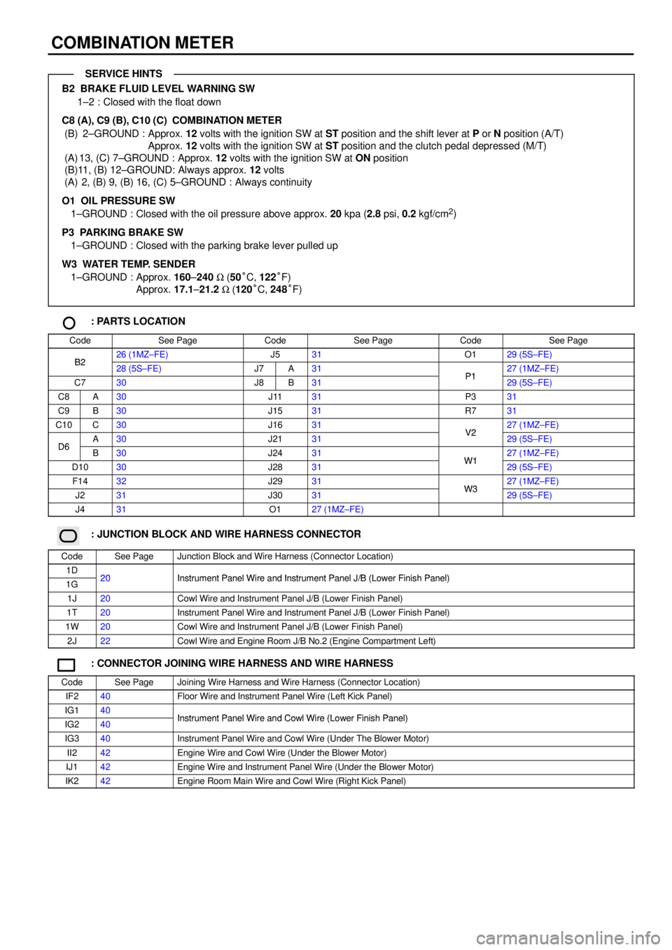
COMBINATION METER
B2 BRAKE FLUID LEVEL WARNING SW
1±2 : Closed with the float down
C8 (A), C9 (B), C10 (C)
COMBINATION METER
(B) 2±GROUND : Approx. 12 volts with the ignition SW at ST position and the shift lever at P or N position (A/T)
Approx. 12 volts with the ignition SW at ST position and the clutch pedal depressed (M/T)
(A) 13, (C) 7±GROUND : Approx. 12 volts with the ignition SW at ON position
(B)11, (B) 12±GROUND: Always approx. 12 volts
(A) 2, (B) 9, (B) 16, (C) 5±GROUND : Always continuity
O1 OIL PRESSURE SW
1±GROUND : Closed with the oil pressure above approx. 20 kpa (2.8 psi, 0.2 kgf/cm
2)
P3 PARKING BRAKE SW
1±GROUND : Closed with the parking brake lever pulled up
W3 WATER TEMP. SENDER
1±GROUND : Approx. 160±240 W (50°C, 122°F)
Approx. 17.1±21.2 W (120°C, 248°F)
: PARTS LOCATION
CodeSee PageCodeSee PageCodeSee Page
B226 (1MZ±FE)J531O129 (5S±FE)B228 (5S±FE)J7A31P127 (1MZ±FE)
C730J8B31P129 (5S±FE)
C8A30J1131P331
C9B30J1531R731
C10C30J1631V227 (1MZ±FE)
D6A30J2131V229 (5S±FE)D6B30J2431W127 (1MZ±FE)
D1030J2831W129 (5S±FE)
F1432J2931W327 (1MZ±FE)
J231J3031W329 (5S±FE)
J431O127 (1MZ±FE)
: JUNCTION BLOCK AND WIRE HARNESS CONNECTOR
CodeSee PageJunction Block and Wire Harness (Connector Location)
1D20Instrument Panel Wire and Instrument Panel J/B (Lower Finish Panel)1G20Instrument Panel Wire and Instrument Panel J/B (Lower Finish Panel)
1J20Cowl Wire and Instrument Panel J/B (Lower Finish Panel)
1T20Instrument Panel Wire and Instrument Panel J/B (Lower Finish Panel)
1W20Cowl Wire and Instrument Panel J/B (Lower Finish Panel)
2J22Cowl Wire and Engine Room J/B No.2 (Engine Compartment Left)
: CONNECTOR JOINING WIRE HARNESS AND WIRE HARNESS
CodeSee PageJoining Wire Harness and Wire Harness (Connector Location)
IF240Floor Wire and Instrument Panel Wire (Left Kick Panel)
IG140Instrument Panel Wire and Cowl Wire (Lower Finish Panel)IG240Instrument Panel Wire and Cowl Wire (Lower Finish Panel)
IG340Instrument Panel Wire and Cowl Wire (Under The Blower Motor)
II242Engine Wire and Cowl Wire (Under the Blower Motor)
IJ142Engine Wire and Instrument Panel Wire (Under the Blower Motor)
IK242Engine Room Main Wire and Cowl Wire (Right Kick Panel)
SERVICE HINTS
Page 4514 of 4592

FAN MOTOR OPERATION (1MZ±FE)
With the ignition SW turned on, the current through the ECU±IG fuse flows to the FAN NO.1 relay (Coil side), FAN NO.2 relay
(Coil side) and FAN NO.3 relay (Coil side). Furthermore, the current through the FAN NO.1 relay (Coil side) or the FAN NO.2
relay (Coil side) flows to TERMINAL 3 of the A/C single pressure SW to TERMINAL 2 to TERMINAL 2 of the water temp. SW
No.1 to TERMINAL 1 to GROUND, causing the FAN NO.1 relay to turn off and the FAN NO.2 relay to turn on.
1. LOW SPEED OPERATION
Only when the A/C system is activated or the water temp. SW No.2 is turned on, the A/C condenser fan motor and the
radiator fan motor rotates at low speed.
When the A/C system is activated, the current from ECU±IG fuse flows to the FAN NO.3 relay (Coil side) to TERMINAL 1 of
the diode (A/C) to TERMINAL 2 to TERMINAL (A)12 of the A/C amplifier (Manual A/C) or (B) 2 of the A/C control assembly
(Automatic A/C) causing the FAN NO.3 relay to turn on. As a result, the current through the CDS fuse flows to TERMINAL 2
of the A/C condenser fan motor to TERMINAL 1 to TERMINAL 3 of the FAN NO.2 relay to TERMINAL 5 to TERMINAL 5 of
the FAN NO.3 relay to TERMINAL 3 to TERMINAL 2 of the radiator fan motor to TERMINAL 1 to GROUND. As this flowing in
series for the motors, the motors rotate at low speed.
When the water temp. SW No.2 is turned on, the current from ECU±IG fuse flows to the FAN NO.3 relay (Coil side) to
TERMINAL 1 of the water temp. SW No.2 to GROUND, causing the FAN NO.3 relay to turn on. As a result, the current
through the CDS fuse flows the same route as above, rotating the motors at low speed.
2. HIGH SPEED OPERATION
Only when the A/C single pressure SW is turned off or the water temp. SW No.1 is turned off, the A/C condenser fan motor
and the radiator fan motor rotate at high speed.
When the A/C single pressure SW is turned off, the current from the RDI fuse flows to the FAN NO.1 relay (Point side) to
TERMINAL 2 of the radiator fan motor to TERMINAL 1 to GROUND. At the same time, the current from the CDS fuse flows
to TERMINAL 2 of the A/C condenser fan motor to TERMINAL 1 to TERMINAL 3 of the FAN NO.2 relay to TERMINAL 4 to
GROUND.
As the current flowing in parallel for the motors as above, the motors rotate at high speed.
FAN MOTOR OPERATION (5S±FE)
With the ignition SW turned on, the current through the ECU±IG fuse flows to the FAN NO.1 relay (Coil side), FAN NO.2 relay
(Coil side). furthermore, the current through the FAN NO.1 relay (Coil side) or the FAN NO.2 relay (Coil side) flows to
TERMINAL 3 of the A/C single pressure SW to TERMINAL 2 to TERMINAL 2 of the water temp. SW No.1 to TERMINAL 1 to
GROUND, causing the FAN NO.1 relay to turn off and the FAN NO.2 relay to turn on.
1. LOW SPEED OPERATION
When the ignition SW is turned on and the A/C system is activated, the A/C condenser fan motor and the radiator fan motor
rotates at low speed.
When the A/C system is activated, the current from MG CLT relay flows to the FAN NO.3 relay (Coil side) to GROUND,
causing the FAN NO.3 relay to turn on. As a result, the current through the CDS fuse flows to TERMINAL 2 of the A/C
condenser fan motor to TERMINAL 1 to TERMINAL 3 of the FAN NO.2 relay to TERMINAL 5 to TERMINAL 5 of the FAN
NO.3 relay to TERMINAL 3 to TERMINAL 2 of the radiator fan motor to TERMINAL 1 to GROUND. As this flowing in series
for the motors, the motors rotate at low speed.
2. HIGH SPEED OPERATION
Only when the A/C single pressure SW is turned off or the water temp. SW No.1 is turned off, the A/C condenser fan motor
and the radiator fan motor rotate at high speed.
When the A/C single pressure SW is turned off, the current from the RDI fuse flows to the FAN NO.1 relay (Point side) to
TERMINAL 2 of the radiator fan motor to TERMINAL 1 to GROUND. At the same time, the current from the CDS fuse flows
to TERMINAL 2 of the A/C condenser fan motor to TERMINAL 1 to TERMINAL 3 of the FAN NO.2 relay to TERMINAL 4 to
GROUND.
As the current flowing in parallel for the motors as above, the motors rotate at high speed.
A3 A/C SINGLE PRESSURE SW
3±2 : Open above approx. 15.5 kgf/cm2
(224 psi, 1520 kpa)
Closed below approx. 12.5 kgf/cm2 (181 psi, 1225 kpa)
W4 WATER TEMP. SW NO.1
2±1 : Open above approx. 95°C (203° F)
W5 WATER TEMP. SW NO.2 (1MZ±FE)
1±GROUND : Closed above approx. 90°C (194°F)
SYSTEM OUTLINE
SERVICE HINTS
Page 4528 of 4592
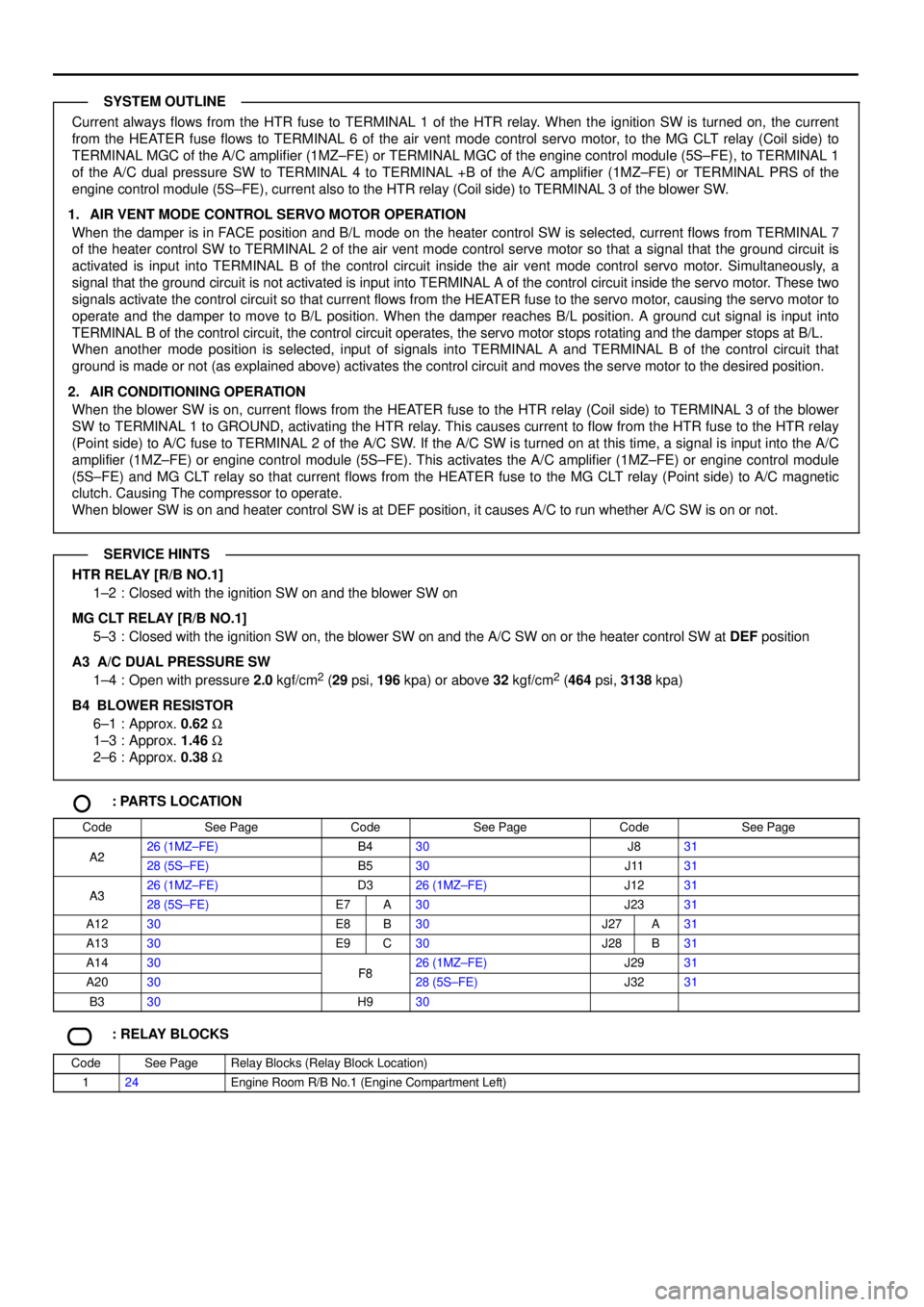
Current always flows from the HTR fuse to TERMINAL 1 of the HTR relay. When the ignition SW is turned on, the current
from the HEATER fuse flows to TERMINAL 6 of the air vent mode control servo motor, to the MG CLT relay (Coil side) to
TERMINAL MGC of the A/C amplifier (1MZ±FE) or TERMINAL MGC of the engine control module (5S±FE), to TERMINAL 1
of the A/C dual pressure SW to TERMINAL 4 to TERMINAL +B of the A/C amplifier (1MZ±FE) or TERMINAL PRS of the
engine control module (5S±FE), current also to the HTR relay (Coil side) to TERMINAL 3 of the blower SW.
1. AIR VENT MODE CONTROL SERVO MOTOR OPERATION
When the damper is in FACE position and B/L mode on the heater control SW is selected, current flows from TERMINAL 7
of the heater control SW to TERMINAL 2 of the air vent mode control serve motor so that a signal that the ground circuit is
activated is input into TERMINAL B of the control circuit inside the air vent mode control servo motor. Simultaneously, a
signal that the ground circuit is not activated is input into TERMINAL A of the control circuit inside the servo motor. These two
signals activate the control circuit so that current flows from the HEATER fuse to the servo motor, causing the servo motor to
operate and the damper to move to B/L position. When the damper reaches B/L position. A ground cut signal is input into
TERMINAL B of the control circuit, the control circuit operates, the servo motor stops rotating and the damper stops at B/L.
When another mode position is selected, input of signals into TERMINAL A and TERMINAL B of the control circuit that
ground is made or not (as explained above) activates the control circuit and moves the serve motor to the desired position.
2. AIR CONDITIONING OPERATION
When the blower SW is on, current flows from the HEATER fuse to the HTR relay (Coil side) to TERMINAL 3 of the blower
SW to TERMINAL 1 to GROUND, activating the HTR relay. This causes current to flow from the HTR fuse to the HTR relay
(Point side) to A/C fuse to TERMINAL 2 of the A/C SW. If the A/C SW is turned on at this time, a signal is input into the A/C
amplifier (1MZ±FE) or engine control module (5S±FE). This activates the A/C amplifier (1MZ±FE) or engine control module
(5S±FE) and MG CLT relay so that current flows from the HEATER fuse to the MG CLT relay (Point side) to A/C magnetic
clutch. Causing The compressor to operate.
When blower SW is on and heater control SW is at DEF position, it causes A/C to run whether A/C SW is on or not.
HTR RELAY [R/B NO.1]
1±2 : Closed with the ignition SW on and the blower SW on
MG CLT RELAY [R/B NO.1]
5±3 : Closed with the ignition SW on, the blower SW on and the A/C SW on or the heater control SW at DEF position
A3 A/C DUAL PRESSURE SW
1±4 : Open with pressure 2.0 kgf/cm
2 (29 psi, 196 kpa) or above 32 kgf/cm2 (464 psi, 3138 kpa)
B4
BLOWER RESISTOR
6±1 : Approx. 0.62 W
1±3 : Approx. 1.46 W
2±6 : Approx. 0.38 W
: PARTS LOCATION
CodeSee PageCodeSee PageCodeSee Page
A226 (1MZ±FE)B430J831A228 (5S±FE)B530J1131
A326 (1MZ±FE)D326 (1MZ±FE)J1231A328 (5S±FE)E7A30J2331
A1230E8B30J27A31
A1330E9C30J28B31
A1430F826 (1MZ±FE)J2931
A2030F828 (5S±FE)J3231
B330H930
: RELAY BLOCKS
CodeSee PageRelay Blocks (Relay Block Location)
124Engine Room R/B No.1 (Engine Compartment Left)
SYSTEM OUTLINE
SERVICE HINTS