Page 3525 of 4592
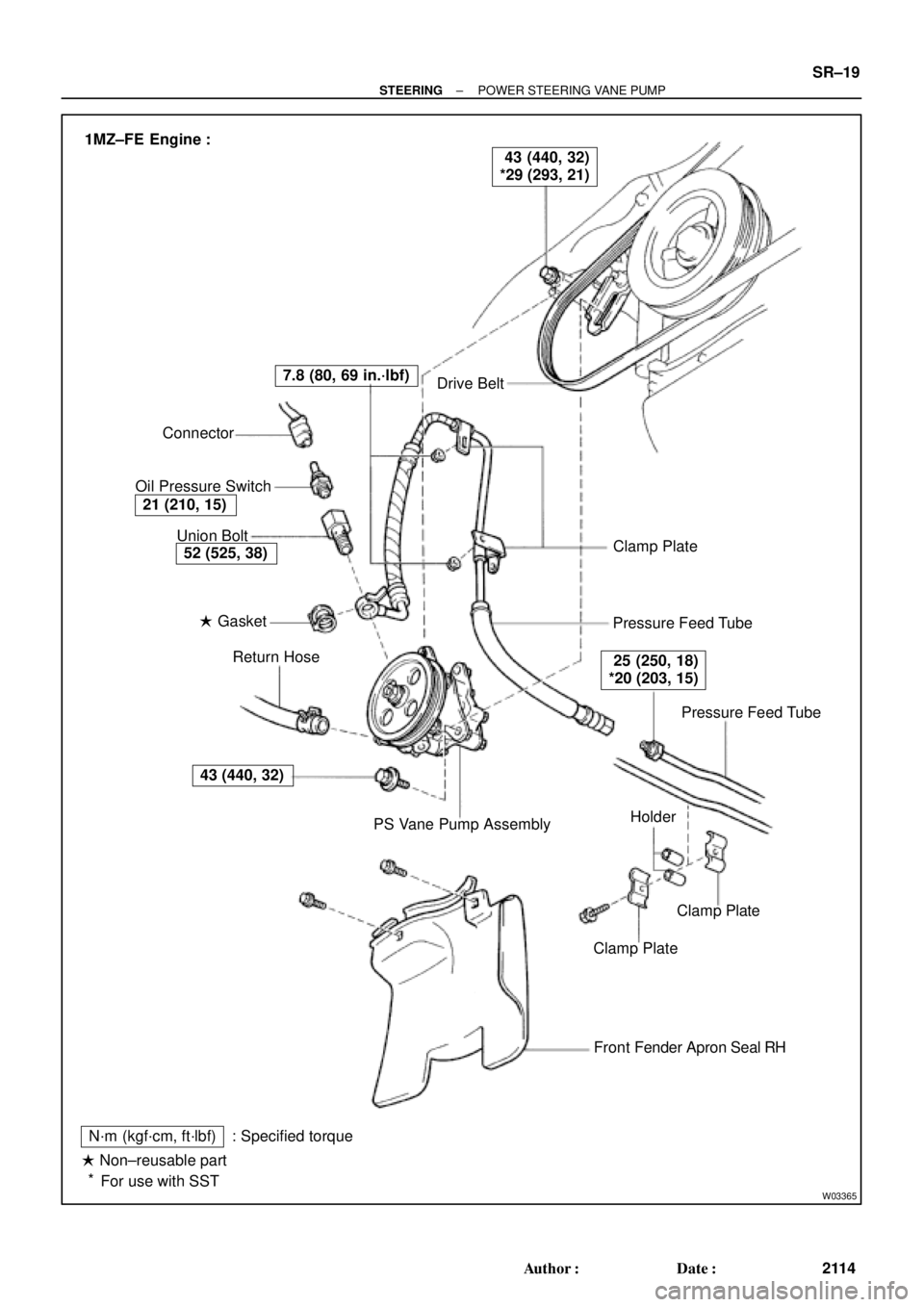
W03365
Drive Belt
Clamp Plate
Pressure Feed Tube
Pressure Feed Tube
Clamp Plate
Clamp Plate
Front Fender Apron Seal RH
N´m (kgf´cm, ft´lbf)
� Non±reusable part
For use with SST: Specified torquePS Vane Pump Assembly Return Hose � Gasket Union Bolt Connector
Oil Pressure Switch
43 (440, 32)
52 (525, 38)
21 (210, 15)
7.8 (80, 69 in.´lbf)
25 (250, 18)
*20 (203, 15)
43 (440, 32)
*29 (293, 21) 1MZ±FE Engine :
Holder
*
± STEERINGPOWER STEERING VANE PUMP
SR±19
2114 Author�: Date�:
Page 3526 of 4592
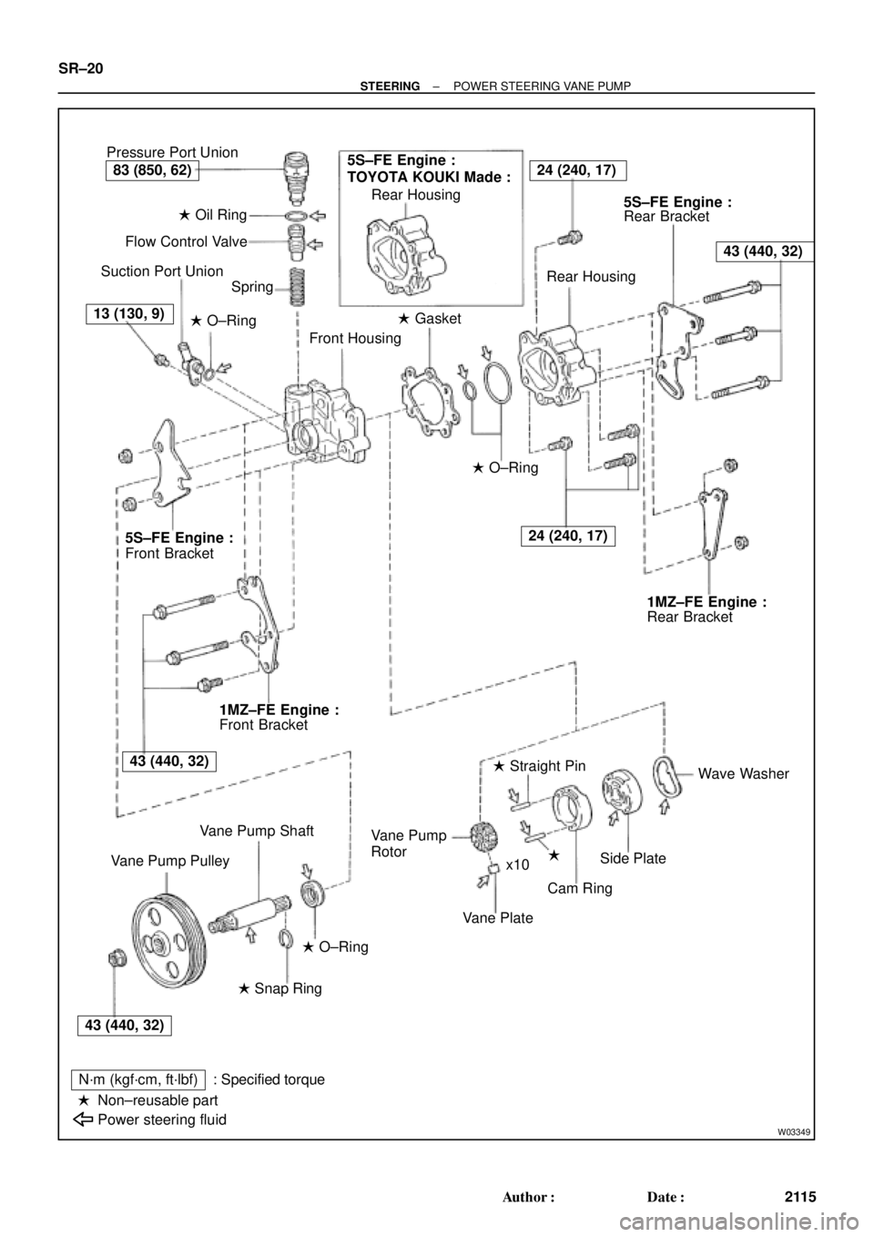
W03349
Pressure Port Union
� Oil Ring
Flow Control Valve
Suction Port Union
Spring
� O±Ring
Front Housing� Gasket Rear Housing
Rear Bracket
Rear Housing
� O±Ring
Rear Bracket
Wave Washer
�
Cam Ring � Straight Pin
Vane Plate Rotor
Side Plate Vane Pump
x10
� O±Ring
� Snap Ring
N´m (kgf´cm, ft´lbf)
Non±reusable part
Power steering fluid: Specified torque Vane Pump Shaft
Vane Pump PulleyFront Bracket Front Bracket
�
5S±FE Engine :
TOYOTA KOUKI Made :24 (240, 17)
43 (440, 32)
24 (240, 17)
83 (850, 62)
13 (130, 9)
5S±FE Engine :5S±FE Engine :
1MZ±FE Engine :1MZ±FE Engine :
43 (440, 32)
43 (440, 32) SR±20
± STEERINGPOWER STEERING VANE PUMP
2115 Author�: Date�:
Page 3527 of 4592

SR06O±01
W04220
5S±FE Engine :
1MZ±FE Engine :
Pressure
Feed TubeSST SST
W03360
Example 5S±FE Engine :
A
B
± STEERINGPOWER STEERING VANE PUMP
SR±21
2116 Author�: Date�:
REMOVAL
1. REMOVE FRONT FENDER APRON SEAL RH
Remove the 2 bolts.
2. DISCONNECT RETURN HOSE
NOTICE:
Take care not to spill fluid on the drive belt.
3. DISCONNECT PRESSURE FEED TUBE
(a) 5S±FE Engine:
Remove the clamp plate set bolt and nut.
(b) 5S±FE Engine:
Remove the 2 clamp plates and 2 holders from the tube.
(c) 5S±FE Engine:
Remove the clamp from the tube.
(d) 1MZ±FE Engine:
Remove the 2 clamp plate set nuts.
(e) 1MZ±FE Engine:
Remove the bolt.
(f) 1MZ±FE Engine:
Remove the 2 clamp plates and 2 holders from the tube.
(g) 5S±FE and 1MZ±FE Engines:
Using SST, disconnect the tube.
SST 09631±22020
4. REMOVE DRIVE BELT
Loosen the 2 (A and B) bolts.
5. REMOVE PS VANE PUMP ASSEMBLY WITH PRES-
SURE FEED TUBE
(a) Disconnect the connector from the oil pressure switch.
(b) Loosen bolt A sufficiently so that pump assembly can be
removed.
HINT:
Bolt A cannot be removed.
6. REMOVE PRESSURE FEED TUBE
(a) Remove the oil pressure switch from the union bolt.
NOTICE:
Be careful not to drop the switch.
If the switch is dropped or strongly damaged, replace it with a
new one.
(b) Remove the union bolt and gasket.
Page 3534 of 4592
SR06S±01
W03361
5S±FE Engine :
1MZ±FE Engine :Pressure Feed Tube
Stopper
Pressure
Feed
StopperTube
W03360
Example 5S±FE Engine :
A
B
W03542
5S±FE Engine :
SST
Fulcrum
Length SR±28
± STEERINGPOWER STEERING VANE PUMP
2123 Author�: Date�:
INSTALLATION
1. INSTALL PRESSURE FEED TUBE
(a) Torque the union bolt with a new gasket.
HINT:
Make sure the stopper of the tube is touching the front bracket,
as shown, then torque the union bolt.
5S±FE and 1MZ±FE Engines:
Torque: 52 N´m (525 kgf´cm, 38 ft´lbf)
(b) Install the oil pressure switch to the union bolt.
5S±FE and 1MZ±FE Engines:
Torque: 21 N´m (210 kgf´cm, 15 ft´lbf)
2. INSTALL PS VANE PUMP ASSEMBLY WITH PRESS-
ER FEED TUBE
Temporarily tighten the 2 (A and B) bolts.
3. INSTALL DRIVE BELT
(a) Adjust drive belt tension.
(See page SR±3)
(b) 5S±FE Engine:
Using SST, torque the A bolt.
SST 09249±63010
Torque: 29 N´m (293 kgf´cm, 21 ft´lbf)
HINT:
Use a torque wrench with a fulcrum length of 300 mm (11.81
in.).
Page 3535 of 4592

W03543
1MZ±FE Engine :
Engine Wire Clamp
Fulcrum
Length
SST
W04221
5S±FE Engine :
1MZ±FE Engine :Fulcrum
Length
SST Pressure
Feed Tube
Fulcrum
LengthSST
± STEERINGPOWER STEERING VANE PUMP
SR±29
2124 Author�: Date�:
(c) 1MZ±FE Engine:
Using SST, torque the A bolt.
SST 09249±63010
Torque: 29 N´m (293 kgf´cm, 21 ft´lbf)
HINT:
�Use a torque wrench with a fulcrum length of 300 mm
(11.81 in.).
�Disconnect the clamp with engine wire.
(d) Torque the B bolt.
5S±FE and 1MZ±FE Engines:
Torque: 43 N´m (440 kgf´cm, 32 ft´lbf)
(e) Connect the connector to the oil pressure switch.
NOTICE:
Be careful for oil on the connector.
4. CONNECT PRESSURE FEED TUBE
(a) Using SST, connect the tube.
SST 09631±22020
5S±FE Engine:
Torque: 32 N´m (326 kgf´cm, 24 ft´lbf)
1MZ±FE Engine:
Torque: 20 N´m (203 kgf´cm, 15 ft´lbf)
HINT:
�Use a torque wrench with a fulcrum length of 300 mm
(11.81 in.).
�This torque value is effective in case that SST is parallel
to a torque wrench.
(b) 5S±FE Engine:
Install the clamp to the tube.
(c) 5S±FE Engine:
Install the 2 clamp plates and 2 holders to the tube.
(d) 5S±FE Engine:
Install the clamp plate set bolt.
(e) 5S±FE Engine:
Install the clamp plate set nut.
Torque: 10 N´m (100 kgf´cm, 7 ft´lbf)
(f) 1MZ±FE Engine:
Install the 2 clamp plates and 2 holders to the tube.
(g) 1MZ±FE Engine:
Tighten the bolt.
(h) 1MZ±FE Engine:
Install the 2 clamp plate set nuts.
Torque: 7.8 N´m (80 kgf´cm, 69 in.´lbf)
5. CONNECT RETURN HOSE
Page 3539 of 4592
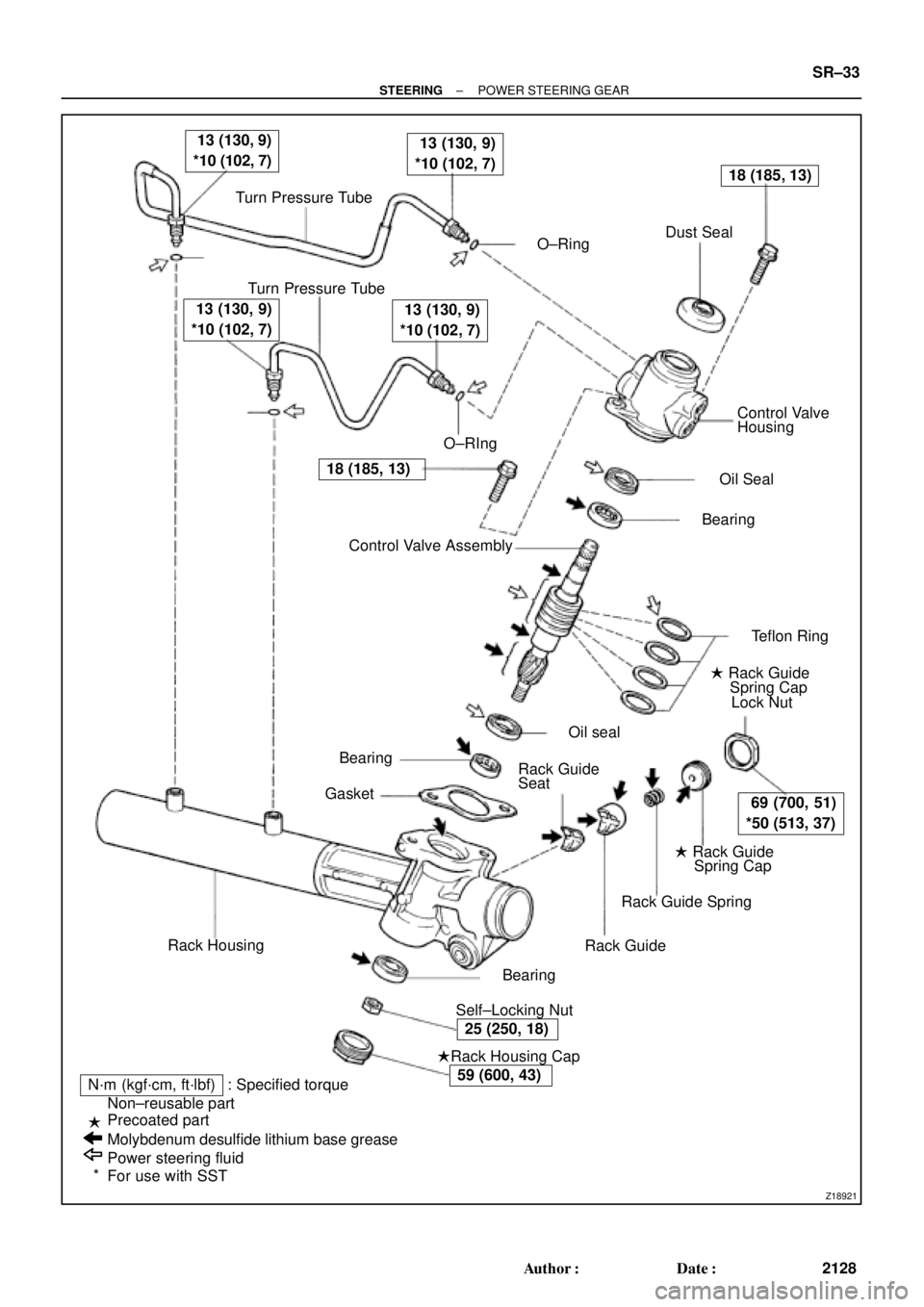
Z18921
Turn Pressure Tube
� O±RingDust Seal
Turn Pressure Tube
� O±RIngControl Valve
Housing
� Oil Seal
� Bearing
� Teflon Ring
� Rack Guide
Spring Cap
Lock Nut
� Rack Guide
Spring Cap
Rack Guide Spring
Rack Guide
� Self±Locking Nut� Bearing
�Rack Housing Cap
N´m (kgf´cm, ft´lbf) : Specified torque
Non±reusable part
Precoated part
Molybdenum desulfide lithium base grease
Power steering fluid
For use with SSTRack Housing� Bearing
� GasketControl Valve Assembly � �
13 (130, 9)
*10 (102, 7) 13 (130, 9)
*10 (102, 7)
18 (185, 13)
69 (700, 51)
*50 (513, 37)
25 (250, 18)
59 (600, 43)
18 (185, 13)
13 (130, 9)
*10 (102, 7) 13 (130, 9)
*10 (102, 7)
�
�
*Rack Guide
Seat� Oil seal
± STEERINGPOWER STEERING GEAR
SR±33
2128 Author�: Date�:
Page 4020 of 4592
![TOYOTA CAMRY 1999 Service Repair Manual B
[A]: Part Code
[B]: Part Name
[C]: Part Number
Toyota Part Number are indicated.
Not all of the above part numbers of the connector are established for the supply. In case of ordering a connector
or](/manual-img/14/57448/w960_57448-4019.png "TOYOTA CAMRY 1999 Service Repair Manual B
[A]: Part Code
[B]: Part Name
[C]: Part Number
Toyota Part Number are indicated.
Not all of the above part numbers of the connector are established for the supply. In case of ordering a connector
or")
B
[A]: Part Code
[B]: Part Name
[C]: Part Number
Toyota Part Number are indicated.
Not all of the above part numbers of the connector are established for the supply. In case of ordering a connector
or terminal with wire, please confirm in advance if there is supply for it using
ªParts Catalog Newsº (published by
Parts Engineering Administration Dept.).
A 5�� ��
90980±11194
L PART NUMBER OF CONNECTORS
Code Part Name Part NumberCode Part NamePart Number
A 1
A 2
A 4
A 6
A 7A/C Ambient Temp. Sensor
A/C Condenser Fan Motor
A/C Triple Pressure SW (A/C Dual and
Single Pressure SW)
A/T Oil Temp. Sensor
ABS Actuator
ABS Actuator90980±11070
90980±11237
90980±10943
90980±11413
90980±11151D 4
D 5
D 6
D 7
D 8
D 9
D10
D11Diode (Door Courtesy Light)
Diode (Key Off Operation)
Diode (Luggage Compartment Light)
Door Lock Control Relay
Door Courtesy Light LH
Door Courtesy Light RH
Door Courtesy SW LH
Door Courtesy SW RH90980±11608
90980±10962
90980±11608
90980±10848
90980±11148
90980±11097
A 8ABS Speed Sensor Front LH
90980±10941
A 9ABS Speed Sensor Front RH
90980±11856 A10Airbag Sensor Front LH
A11Airbag Sensor Front RHD12Door Courtesy SW Front LH
90980±11156 D13Door Courtesy SW Front RH
D14Door Courtesy SW Rear LH
Door Courtesy SW Rear RH
D15
[B]�� ��[C]
A12
Auto Antenna Motor90980±11194 A 3
A/C Condenser Fan Relay90980±10940
[A]
90980±11009
90980±11002
D16
D17Door Key Lock and Unlock SW LH
Door Key Lock and Unlock SW RH90980±11170
Page 4038 of 4592
G
Position of Parts in Engine Compartment
I 1 Idle Air Control Valve
I 2 Ignition Coil and Igniter No.1
I 3 Ignition Coil and Igniter No.2
I 4 Injector No.1
I 5 Injector No.2
I 6 Injector No.3
I 7 Injector No.4
I 8 Intake Air Temp. Sensor
M 1 Manifold Absolute Pressure Sensor
N 1 Noise Filter (Ignition)
O 1 Oil Pressure SW
P 1 Park/Neutral Position SW,A/T Indicator Light SW and
Back±Up Light SW
P 2 Power Steering Oil Pressure SWR 1 Radiator Fan Motor
S 1 Starter
S 2 Starter
T 1 Throttle Position Sensor
V 1 Vehicle Speed Sensor (Combination Meter)
V 2 VSV (EGR)
W 1 Washer Level Warning SW
W 2 Washer Motor
W 3 Water Temp. Sender
W 4 Water Temp. SW No.1