Page 9 of 65

The drivers door has switches ®,®,© & ©
to operate the drivers window, front
passengers window, rear ri")
60G-74E
BEFORE DRIVING
WINDOWS
60G-03-009E
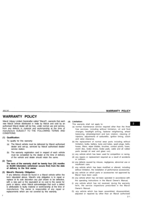
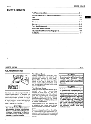
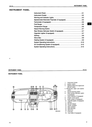
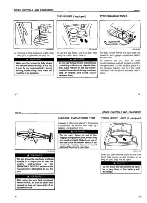
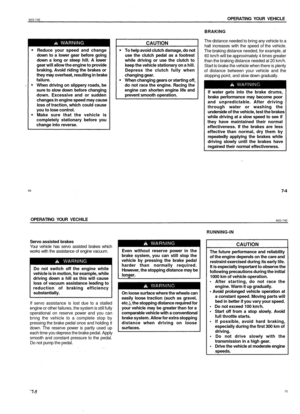
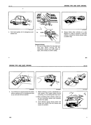
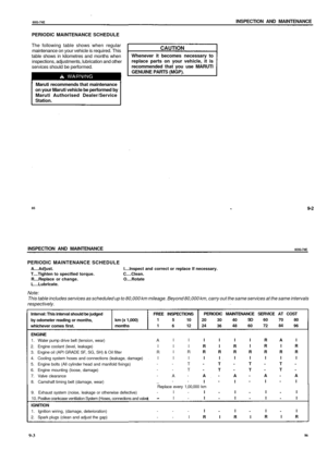
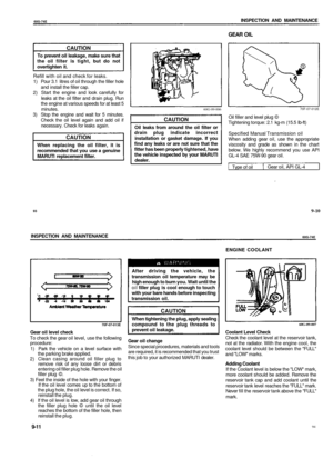
Electric window controls (if equipped)
The driver's door has switches ®,®,© & ©
to operate the driver's window, front
passenger's window, rear right and rear left
passenger's window respectively.
The passenger's door only has a switch ©
to operate the passenger's window. The
electric windows can only be operated when
the ignition switch is in the "ON" position.
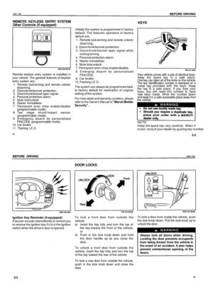
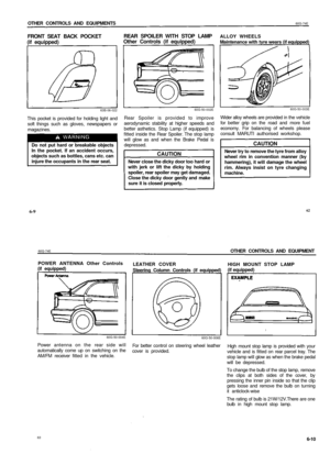
To open a window with the driver's door
switches, push the top part of the switch and
to close the window lift up the top part
of the switch.
6OG-O3-010E
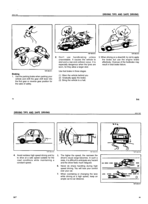
The driver's window has an "auto-down"
feature for added convenience (at toll booths
or drive-through restaurants, for example).
This means you can open the window without
holding the window switch in the "Down"
position. Press the driver's window
switch completely down and release it. To
stop the window before it reaches the
bottom, lift up the switch briefly.
To open or to close a window with the
passenger's door switch, push down or push
up the switch.
19
3-6
BEFORE DRIVING
60G-74E
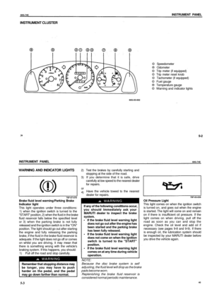
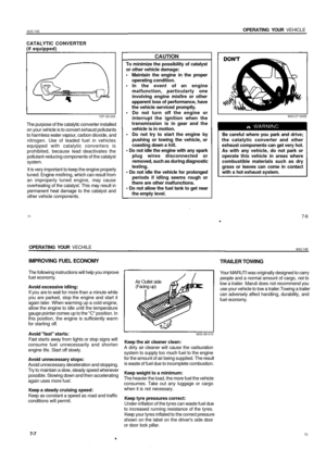
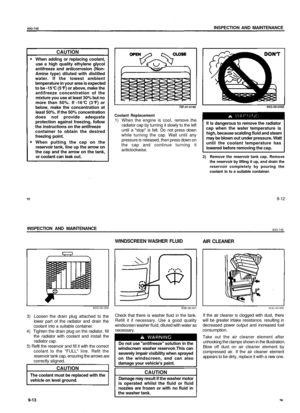
60G-03-011E
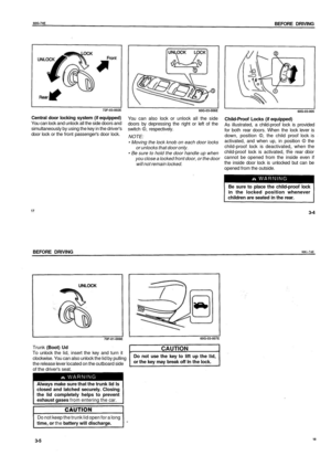
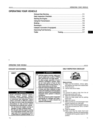
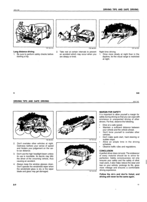
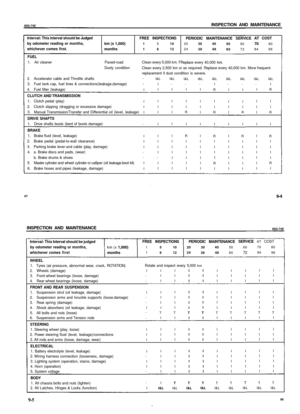
The driver's door also has a lock switch for
the passenger's window. When you push in
the lock side of the switch, the passenger's
windows can not be raised or lowered by
operating either of the switches ®,@,® & ©.
To restore normal operation, push the unlock
side of the switch.
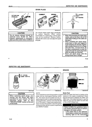
60G-03-012
You should always push the lock side
of the lock switch when there are
children in the vehicle. Children can be
seriously injured if they get part of their
body caught by the window during
operation.
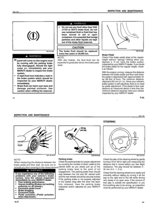
NOTE:
The rear side door windows are not designed
to open fully. They can be opened about 2/3
of the way down.
3-7
20
CAUTION
Since the electric windows consumes
a large amount of electricity, the same
should not be used excessively with
engine in "OFF" condition.
Page 10 of 65

To adjust the interior rearview mirror, set the
selector tab to the day position, then move
the mirror up, dow")
60G-74E
BEFORE DRIVING
MIRRORS
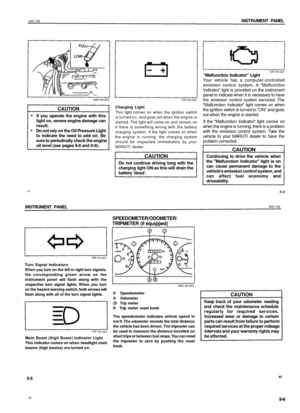
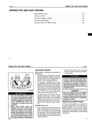
60G-03-013
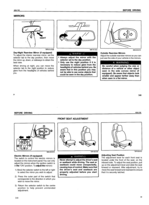
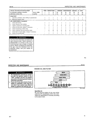
Day-Night Rearview Mirror (if equipped)
To adjust the interior rearview mirror, set the
selector tab to the day position, then move
the mirror up, down, or sideways to obtain the
best view.
When driving at night, you can move the
selector tab to the night position to reduce
glare from the headlights of vehicles behind
you.
Always adjust the mirror with the
selector set to the day position.
Only use the night position if it is
necessary to reduce glare from the
headlights of vehicles behind you. Be
aware that in this position you may
not be able to see some objects that
could be seen in the day position.
Outside Rearview Mirrors
Adjust the outside rearview mirrors so you can
just see the side of your vehicle in the mirrors.
A WARNING
Be careful when judging the size or
distance of a vehicle or other object
seen in the side convex mirror (if
equipped). Be aware that objects look
smaller and appear farther away than
when seen in a flat mirror.
21
3-8
BEFORE DRIVING
6OG-74E
FRONT SEAT ADJUSTMENT
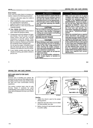
60G-03-014
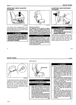
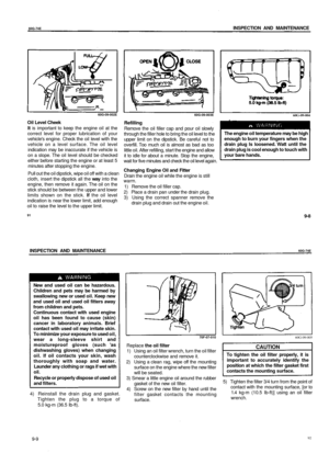
Electric Mirrors (If equipped)
The switch to control the electric mirrors is
located on the instrument panel.You can only
adjust the mirrors when the ignition switch is
in the "ON" position. To adjust the mirrors:
1) Move the selector switch to the left or right
to select the mirror you wish to adjust.
2) Press the outer part of the switch that
corresponds to the direction in which you
wish to move the mirror.
3) Return the selector switch to the centre
position to help prevent unintended
adjustment.
72F-03-016
Never attempt to adjust the driver's seat
or seatback while driving. The seat or
seatback could move unexpectedly,
causing loss of control. Make sure that
the driver's seat and seatback are
properly adjusted before you start
driving.
72F-03-013
Adjusting Seat Position
The adjustment lever for each front seat is
located under the front of the seat, on the
inboard side. To adjust the seat position, pull
up on the adjustment lever and slide the seat
forward or rearward. After adjustment, try to
move the seat forward and rearward to ensure
that it is securely latched.
3-9
22
Page 11 of 65

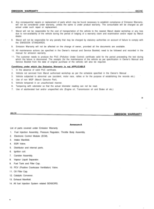
ADJUSTABLE HEAD RESTRAINTS
(if equipped)
606-03-015
If the drivers seat is equipped with a seat
height adjuster knob on the o")
60G-74E
BEFORE DRIVING
DRIVER SEAT HEIGHT ADJUSTER
(if equipped)
ADJUSTABLE HEAD RESTRAINTS
(if equipped)
606-03-015
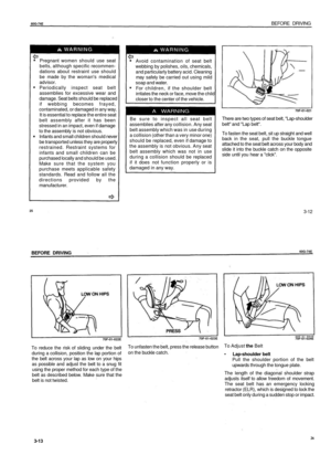
If the driver's seat is equipped with a seat
height adjuster knob on the outboard side of
the seat, adjust the seat to the proper height
by turning the adjuster knob.
WARNING
72F-03-014
Adjusting Seatbacks
The seatbacks can be adjusted to different
angles. To adjust the seatback angle, pull up
the lever on the outboard side of the seat,
move the seatback to the desired position, and
release the lever to lock the seatback in place.
Seatbacks should always be in an
upright position when driving, or seat
belt effectiveness may be reduced. Seat
belts are designed to offer maximum
protection when seatbacks are in the
fully upright position.
70F-01-019
WARNING
Head restraints are designed to help reduce
the risk of neck injuries in the case of an
accident. Adjust the head restraint to the
position which places the top of the head
restraint closest to the top or your ears.
23
3-10
BEFORE DRIVING
60G-74E
SEAT BELTS
60G-03-016
To raise the head restraint, pull upward ort the
restraint until it clicks. To lower the restraint,
push down on the restraint while holding in
the lock lever. If a head restraint must be
removed (for cleaning, replacement, etc.),
push in the lock lever and pull the head
restraint all the way out.
70F-01-022E
Wear your Seat Belts at All Times.
WARNING
Never allow persons to ride in the
cargo area of a vehicle. In the event
of an accident, there is a much
greater risk of injury for persons who
are not riding In a seat with their seat
belt securely fastened.
Seat belts should always be adjusted
so the lap portion of the belt is worn
low across the pelvis, not across the
waist. Shoulder straps should be
WARNING
1 worn on the outside shoulder only,
and never under the arm. Seat belts
should never be worn with the straps
twisted and should be adjusted as
tightly as is comfortable to provide
the protection for which they have
been designed. A slack belt will
provide less protection than one
which is snug.
Make sure that each seat belt buckle
is inserted into the proper buckle
catch. It is possible to cross the
buckles in the rear seat.
Do not wear your seat belt over hard
or breakable objects in your pockets
or on your clothing. If an accident
occurs, objects such as glasses,
pens, etc. under the seat belt can
cause injury.
Never use the same seat belt on
more than one occupant and never
attach a seat belt over an infant or
child being held on an occupant's
lap. Such seat belt use could cause
serious injury in the event of an
accident. _K
3-11
24
Page 12 of 65

60G-74E
BEFORE DRIVING
Pregnant women should use seat
belts, although specific recommen-
dations about restraint use should
be made by the woman's medical
advisor.
Periodically inspect seat belt
assemblies for excessive wear and
damage. Seat belts should be replaced
if webbing becomes frayed,
contaminated, or damaged in any way.
It is essential to replace the entire seat
belt assembly after it has been
stressed in an impact, even if damage
to the assembly is not obvious.
Infants and small children should never
be transported unless they are properly
restrained. Restraint systems for
infants and small children can be
purchased locally and should be used.
Make sure that the system you
purchase meets applicable safety
standards. Read and follow all the
directions provided by the
manufacturer.
Avoid contamination of seat belt
webbing by polishes, oils, chemicals,
and particularly battery acid. Cleaning
may safely be carried out using mild
soap and water.
For children, if the shoulder belt
irritates the neck or face, move the child
closer to the center of the vehicle.
A WARNING
Be sure to inspect all seat belt
assemblies after any collision. Any seat
belt assembly which was in use during
a collision (other than a very minor one)
should be replaced, even if damage to
the assembly is not obvious. Any seat
belt assembly which was not in use
during a collision should be replaced
if it does not function properly or is
damaged in any way.
70F-01-021
There are two types of seat belt, "Lap-shoulder
belt" and "Lap belt".
To fasten the seat belt, sit up straight and well
back in the seat, pull the buckle tongue
attached to the seat belt across your body and
slide it into the buckle catch on the opposite
side until you hear a "click".
25
3-12
BEFORE DRIVING
60G-74E
70F-01-022E
To reduce the risk of sliding under the belt
during a collision, position the lap portion of
the belt across your lap as low on your hips
as possible and adjust the belt to a snug fit
using the proper method for each type of the
belt as described below. Make sure that the
belt is not twisted.
70F-01-023E
To unfasten the belt, press the release button
on the buckle catch.
70F-01-024E
To Adjust the Belt
• Lap-shoulder belt
Pull the shoulder portion of the belt
upwards through the tongue plate.
The length of the diagonal shoulder strap
adjusts itself to allow freedom of movement.
The seat belt has an emergency locking
retractor (ELR), which is designed to lock the
seat belt only during a sudden stop or impact.
3-13
26
Page 13 of 65

60Q-74E
BEFORE DRIVING
70F-01-025
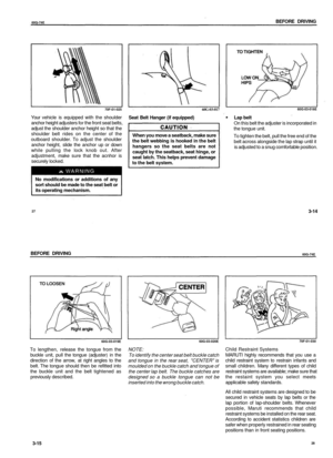
Your vehicle is equipped with the shoulder
anchor height adjusters for the front seat belts,
adjust the shoulder anchor height so that the
shoulder belt rides on the center of the
outboard shoulder. To adjust the shoulder
anchor height, slide the anchor up or down
while pulling the lock knob out. After
adjustment, make sure that the acnhor is
securely locked.
No modifications or additions of any
sort should be made to the seat belt or
its operating mechanism.
60G-03-017
Seat Belt Hanger (if equipped)
When you move a seatback, make sure
the belt webbing is hooked in the belt
hangers so the seat belts are not
caught by the seatback, seat hinge, or
seat latch. This helps prevent damage
to the belt system.
60G-03-018E
Lap belt
On this belt the adjuster is incorporated in
the tongue unit.
To tighten the belt, pull the free end of the
belt across alongside the lap strap until it
is adjusted to a snug comfortable position.
27
3-14
BEFORE DRIVING
60G-74E
60G-03-019E
To lengthen, release the tongue from the
buckle unit, pull the tongue (adjuster) in the
direction of the arrow, at right angles to the
belt. The tongue should then be refitted into
the buckle unit and the belt tightened as
previously described.
60G-03-020E
NOTE:
To identify the center seat belt buckle catch
and tongue in the rear seat, "CENTER" is
moulded on the buckle catch and tongue of
the center lap belt. The buckle catches are
designed so a buckle tongue can not be
inserted into the wrong buckle catch.
70F-01-030
Child Restraint Systems
MARUTI highly recommends that you use a
child restraint system to restrain infants and
small children. Many different types of child
restraint systems are available; make sure that
the restaint system you select meets
applicable safety standards.
All child restraint systems are designed to be
secured in vehicle seats by lap belts or the
lap portion of lap-shoulder belts. Whenever
possible, Maruti recommends that child
restraint systems be installed on the rear seat.
According to accident statistics children are
safer when properly restrained in rear seating
positions than in front seating positions.
3-15
28
Page 14 of 65

60G-74E
BEFORE DRIVING
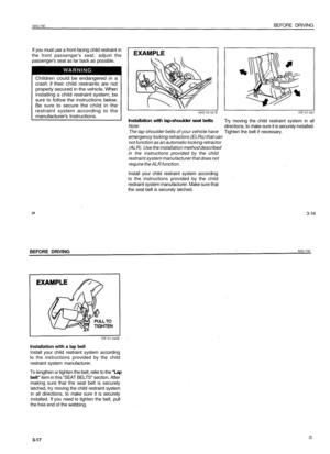
If you must use a front-facing child restraint in
the front passenger's seat, adjust the
passenger's seat as far back as possible.
Children could be endangered in a
crash if their child restraints are not
properly secured in the vehicle. When
installing a child restraint system, be
sure to follow the instructions below.
Be sure to secure the child in the
restraint system according to the
manufacturer's Instructions.
60G-03-021E
Installation with lap-shoulder seat belts
Note:
The lap-shoulder belts of your vehicle have
emergency locking retractors (ELRs) that can
not function as an automatic locking retractor
(ALR). Use the installation method described
in the instructions provided by the child
restraint system manufacturer that does not
require the ALR function.
Install your child restraint system according
to the instructions provided by the child
restraint system manufacturer. Make sure that
the seat belt is securely latched.
70F-01-031
Try moving the child restraint system in all
directions, to make sure it is securely installed.
Tighten the belt if necessary.
29
3-16
BEFORE DRIVING
60G-74E
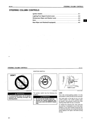
70F-01-032E
Installation with a lap belt
Install your child restraint system according
to the instructions provided by the child
restraint system manufacturer.
To lengthen or tighten the belt, refer to the "Lap
belt" item in this "SEAT BELTS" section. After
making sure that the seat belt is securely
latched, try moving the child restraint system
in all directions, to make sure it is securely
installed. If you need to tighten the belt, pull
the free end of the webbing.
3-17
30
Page 15 of 65

60G-74E
STEERING COLUMN CONTROLS
STEERING COLUMN CONTROLS
ignition Switch 4.1
Lighting/Tum Signal Control Lever 4-2
Windscreen Wiper and Washer Lever 4-4
Horn 4.5
Rear Wiper and Washer(lf equipped) 4-5
31
STEERING COLUMN CONTROLS
60G-74E
IGNITION SWITCH
60G-04-001E
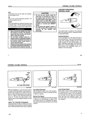
70F-02-002
To avoid possible injury, do not operate
controls by reaching through the
steering wheel.
The ignition switch has the following four
positions:
Do not use any locally made key.
Should you require duplicate key,
place your order with MARUTI dealer
only.
60G-04-002E
LOCK
This is the normal parking position. It is the
only position in which the key can be removed.
You must push in the key to turn it to the
"LOCK" position. The "LOCK" position locks
the ignition, and prevents normal use of the
steering wheel after the key is removed.
To release the steering lock, fully insert the
key and turn it clockwise to one of the other
positions. If you have trouble turning the key
to unlock the steering, try turning the steering
wheel slightly to the right or left while turning
the key.
4-1
32
Page 16 of 65

6OG-74E
STEERING COLUMN CONTROLS
ACC
Accessories such as the radio can operate,
but the engine is off.
ON
This is the normal operating position. All
electrical systems are on.
START
This is the position for starting the engine using
the starter motor. The key should be released
from this position as soon as the engine starts.
Never remove the ignition key while
the vehicle is moving. The steering
wheel will lock and you will not be
able to steer the vehicle.
Do not leave children alone In a
parked vehicle. Unattended children
could cause accidental movement of
the vehicle, which could result in
severe personal Injury.
Always remove the key when parked
to prevent unintentional operation of
the vehicle and to improve security.
LIGHTING/TURN SIGNAL
CONTROL LEVER
CAUTION
Do not use the starter motor for
more than 15 seconds at a time. If
the engine does not start; wait 15
seconds before trying again. If the
engine does not start after several
attempts, check the fuel and ignition
systems or consult your MARUTI
dealer.
Do not leave the ignition switch in
the "ON" position if the engine is not
running as the battery will
discharge.
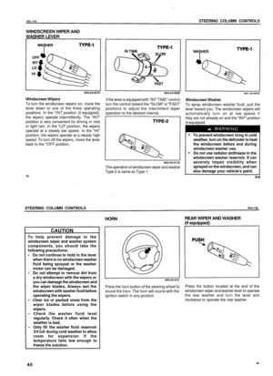
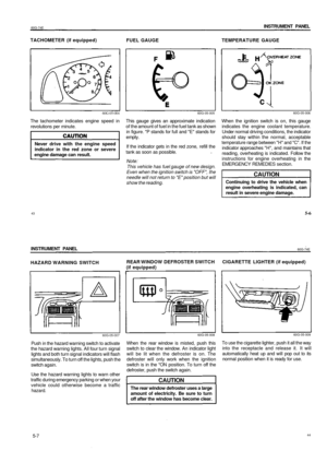
60G-04-003
This control lever is located on the outboard
side of the steering column. Operate the lever
as described below.
Lighting Operation
To turn the lights on or off, twist the knob on
the end of the lever. There are three positions:
in the "OFF" position all lights are off; in the
middle position the front parking lights, tail-
lights, registration plate light, and instrument
lights are on, but the headlights are off; in the
third position the headlights come on in
addition to the other lights.
33
4-2
STEERING COLUMN CONTROLS
60G-74E
With the headlights on, push the lever forward
to switch to the high beams (main beams) or
pull the lever toward you to switch to the low
beams. When the high beams (main beams)
are on, a light on the instrument panel will
come on. To flash the high beams (main
beams) pull the lever slightly towards you and
release it.
Lights "On" Reminder (if Equipped)
A buzzer/chime sounds to remind you to turn
off the lights if they are left on when the ignition
key is removed and the driver's door is opened.
Turn Signal Operation
With the ignition switch in the "ON" position,
move the lever up or down to activate the left
or right turn signals.
Normal Turn Signal
Move the lever clockwise until it clicks to signal
a right turn or anticlockwise to signal a left
turn. When the turn is completed, the signal
will cancel and the lever will return to its normal
position.
6OG-04-006
Lane Change Signal
Some times, such as when changing lanes,
the steering wheel is not turned far enough
to cancel the turn signal. For convenience,
you can flash the turn signal by moving the
lever part way and holding it there. The
lever will return to its normal position when
you release it.
4-3
34
60G-04-006
60G-04-005
60G-04-004E